8. Computer controlled machining
This week’s assignment is about computer controlled machining, I could compare it to the week of electronic production when we used the Roland Mill only this time on a much larger scale, that implies increasing security measures and paying attention to the files that we are going to generate so as not to harm us or the machine.
Assignment
group assignment:
- do your lab’s safety training
- test runout, alignment, speeds, feeds, materials, and toolpaths for our machine
individual assignment:
- make (design+mill+assemble) something big (~meter-scale)
Group assignment
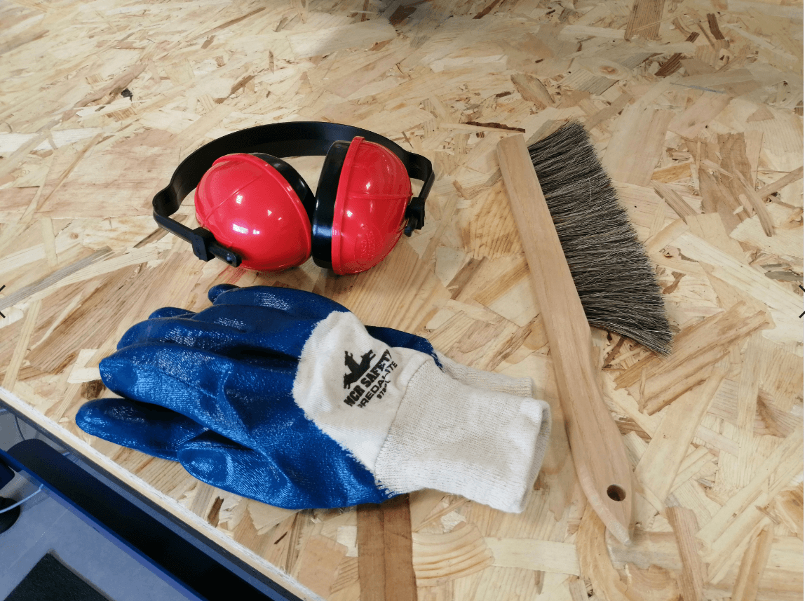
I consider this assignment important because we are going to work with a machine of considerable size and that it can easily cause an accident, the first thing to do is use the appropriate equipment to proceed to work with the machine, I decided to use safety glasses, gloves , hearing protectors and a brush to clean the remains of OSB that may remain after the process (it is important to clarify that the brush should not be used while the machine is running)
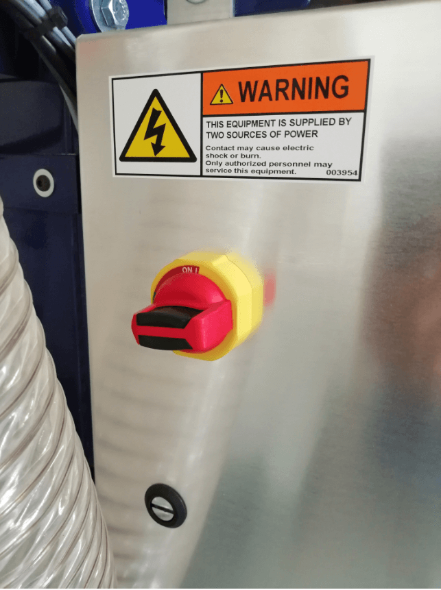
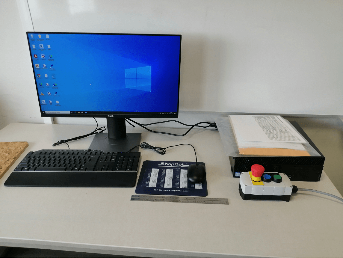
To start working with the equipment we must first activate the switch located on the side of the Shopbot, this is responsible for turning on the machine, there is also another switch linked to a key, this is responsible for activating the spindle, we must check that both are in the activated position
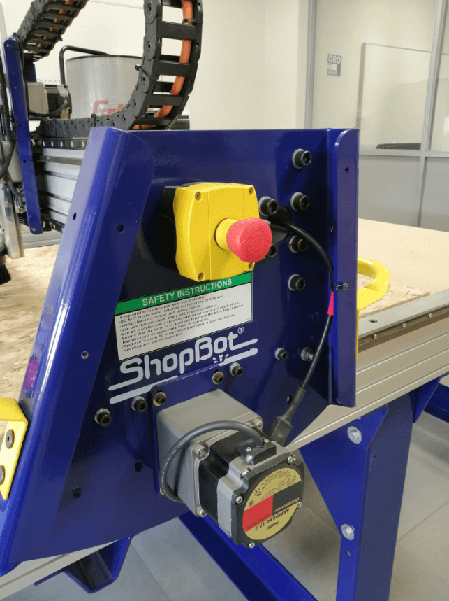
Shopbot also has emergency switches, we must remember where these buttons are located so that in the event of any unforeseen event we can press them as quickly as possible and thus avoid damage to the machine or person, for efficiency reasons we place the main controller next to the PC so that the Shopbot can be stopped by the program or by using the emergency button.
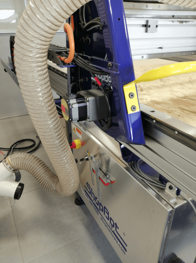
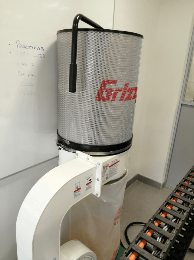
We must also not forget to activate the air filter that will be responsible for sucking up all the waste from the material we are working on.
test runout, alignment, speeds, feeds, materials, and toolpaths for our machine Pending due lab acces.
Individual assignment
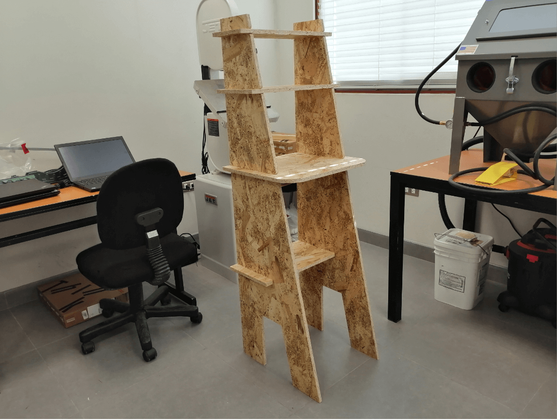
To perform this task I searched for ideas in previous works to have a reference, in the end I decided to make a coffee station, which will be used in the laboratory to store coffee, tea, cookies, sugar and other things.
The most important part is to define the material that I am going to use, since the laboratory has that maker essence, I decided to work with OSB (1.2 x 2.44 meters and 15mm thickness), the piece will be designed in Inventor, later processed in Vcarve and finally machined in our Shopbot.
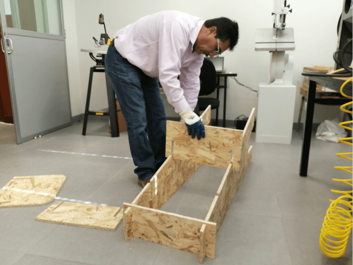
All the furniture will be assembled by press fit so it will not be necessary to use screws, but it will be very important to define the thickness of the joints to have a perfect assembly.
Design
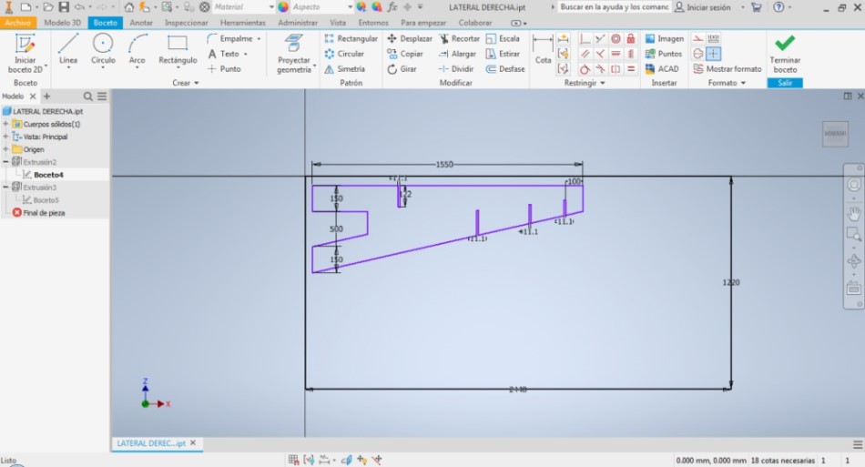
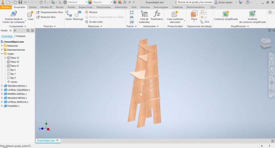
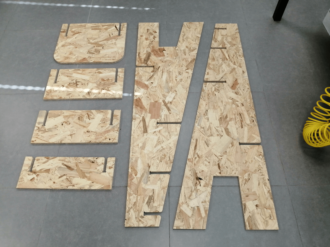
The design is relatively simple, it is made up of a total of 6 pieces, I decided to try the fillets to better fit the piece, the value I assigned to the fillet was 10mm, which I think will be enough for our furniture, another important value is the height that I defined as 145cm and I think that those are the most outstanding values of the furniture.
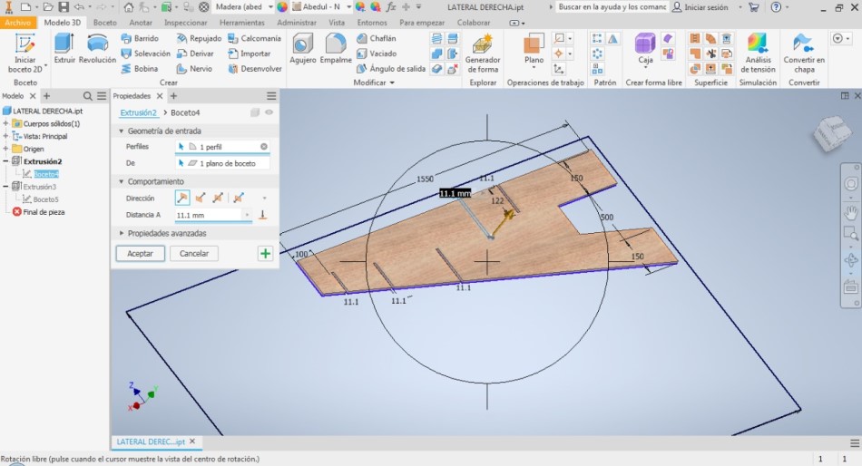
With the sketch in 2D we already have everything we need to export the DXF files to Vcarve, but I decided to make extrusions and turn them to a 3D shape to appreciate the final result, I also gave the material wood texture so it will look as close as possible to reality.
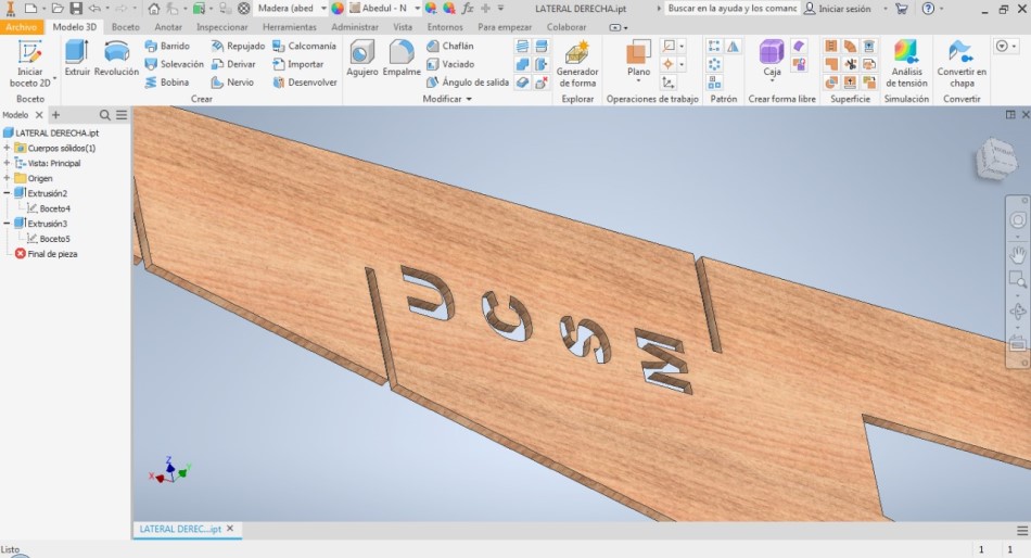
I decided to add letters to the sides of the longest plates with the acronym of the university “UCSM” since Vcarve allows creating a hole or a pocket from the same sketch so I decided to leave them open to both possibilities and later in Vcarve I will finish defining the type of toolpath that I will assign to those letters.

The application of this furniture may vary since the dimensions that we assign also allow us to place a laptop on top and could help us to place it in a more comfortable position to perform a scan or perhaps load parameters to another machine and in the spaces lower place tools or something else that we see fit.
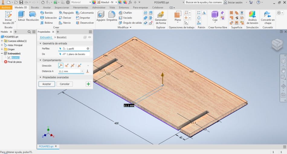
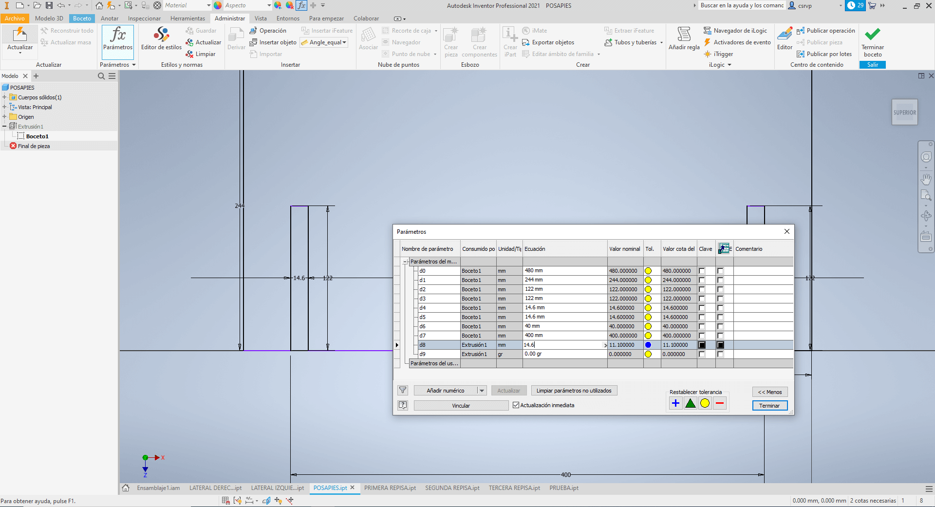
Since we previously learned the advantages of a parametric design, I decided to apply it to this assignment to make changes easier, for example vary the thickness of the material according to the availability of our local distributor, as you can see in the images the initial thickness considered was 11mm and thanks to the parametric design the thickness change was made to 14.6mm due to the actual thickness of our OSB part.
Finally Inventor allows me to export a small animation of the assembly of the pieces to correctly assemble the shelf.

Milling
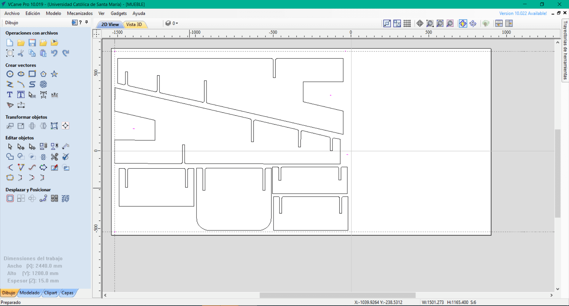
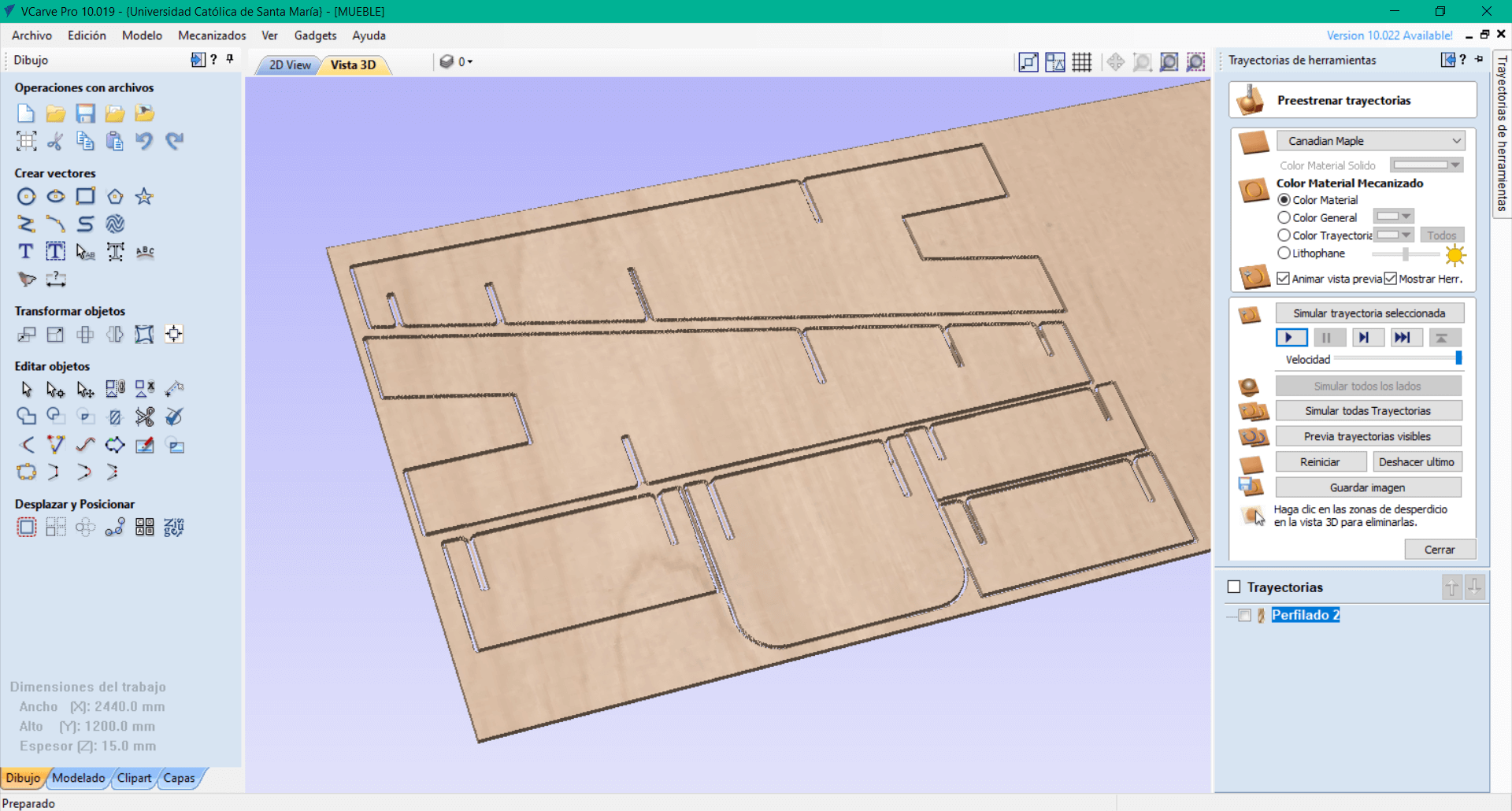
With all our DXF files already generated we can load them to Vcarve, first we must define some important parameters that are Job size (workspace of 2440 x 1200mm), Material thickness and XY Datum position, we must also remember to select the units of measurement in this case millimeters mm.
Then we can import the vector files and with the move option we can display the pieces in all our OSB plate, an extra step would be to use the Join open vectors tool that allows us to solve some errors when importing the piece.
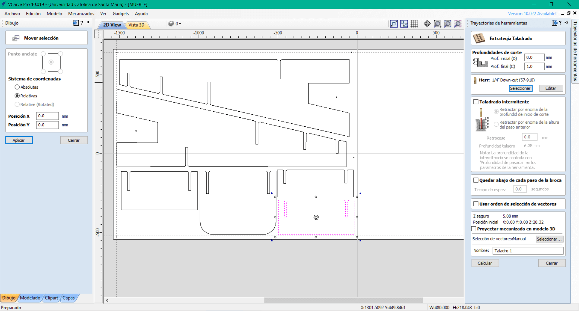
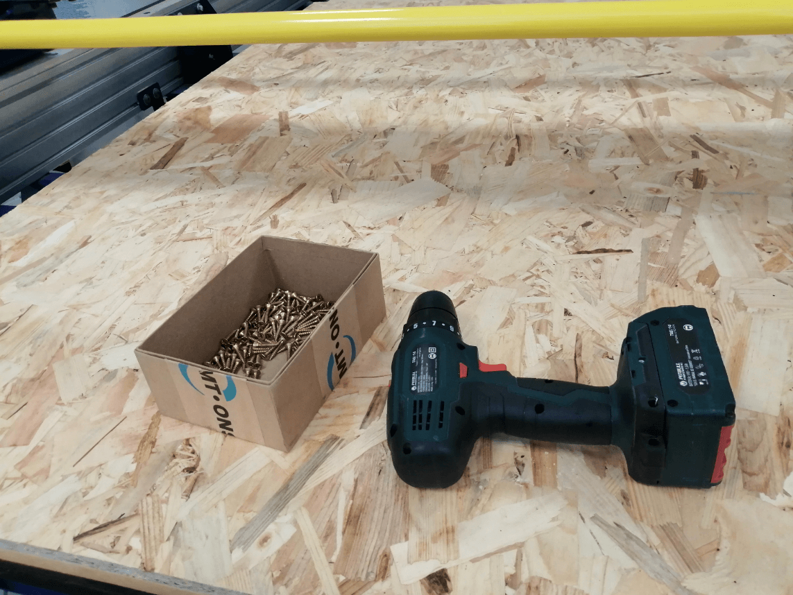
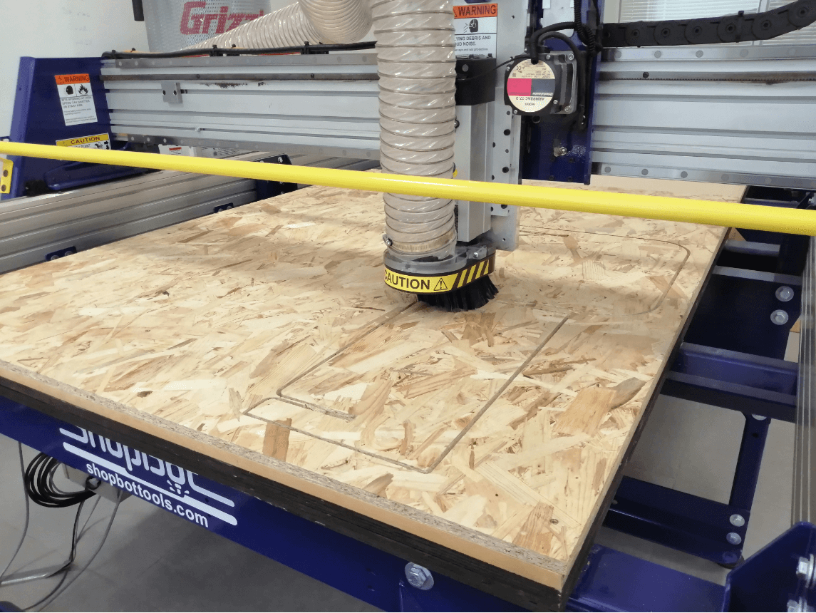
With our pieces placed in the position that we consider appropriate, now we can apply a tip that they taught us to attach the plate to the sacrificial bed, the pieces that we are going to cut are very large, it is necessary to secure the plate with screws.
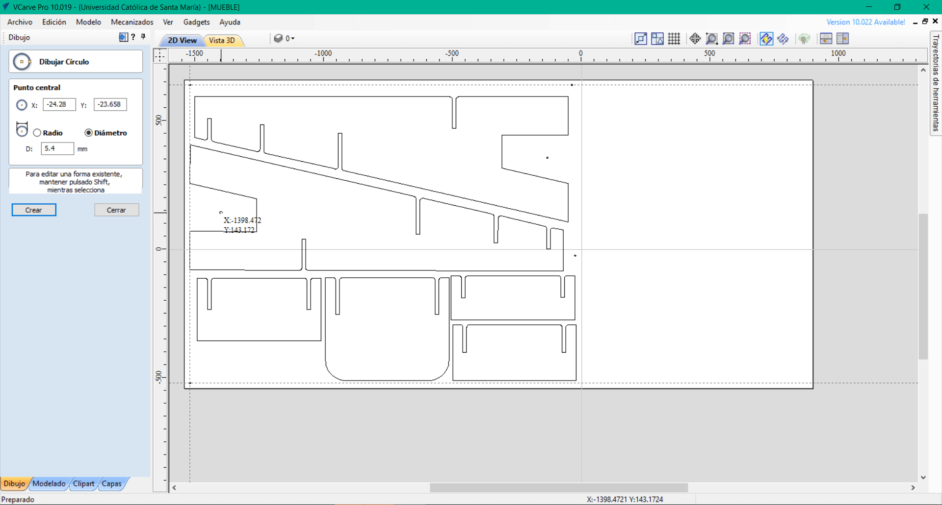
What we must do first is define the diameter of the endmill (6.35mm) and create a circle of the same diameter so that the machine only travels along the Z axis to leave a 1mm deep guide to place the screws, finally we have to create a Drilling toolpath selecting only the screw holes.
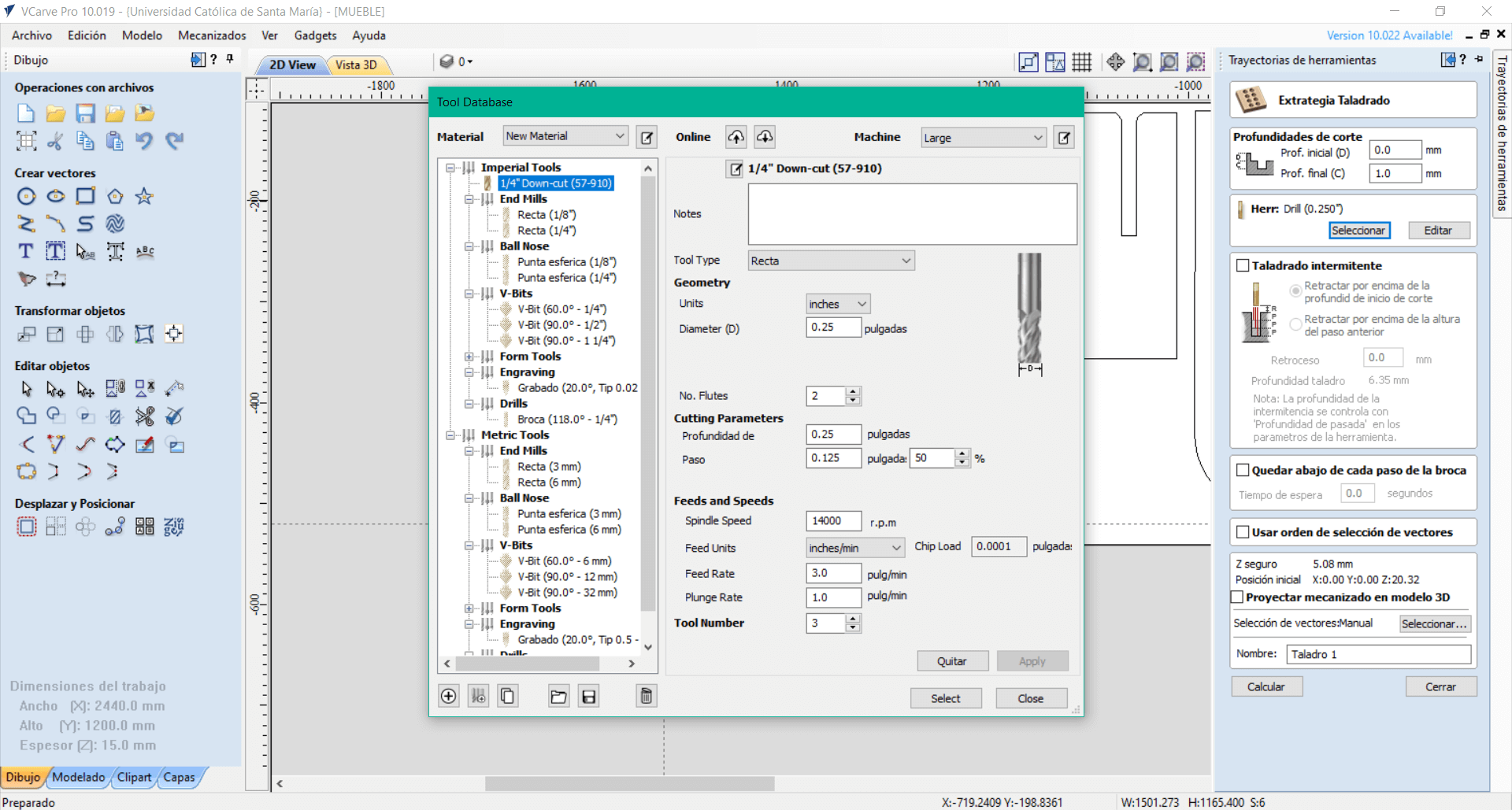
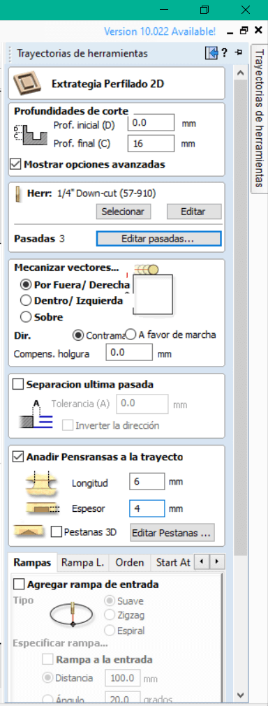
We have a 57910 down-cut endmill that I consider to be adequate for this job, what they explained to us is that the down-cut endmill leaves a more uniform finish when making the toolpaths, our part is not very complex, so I don’t think that affect a lot in the final result.
We assign the important values that the manufacturer gives us such as the diameter, the number of flutes, the pass depths and the most important one is Spindle speed, because if we enter an incorrect value will damage our endmill.
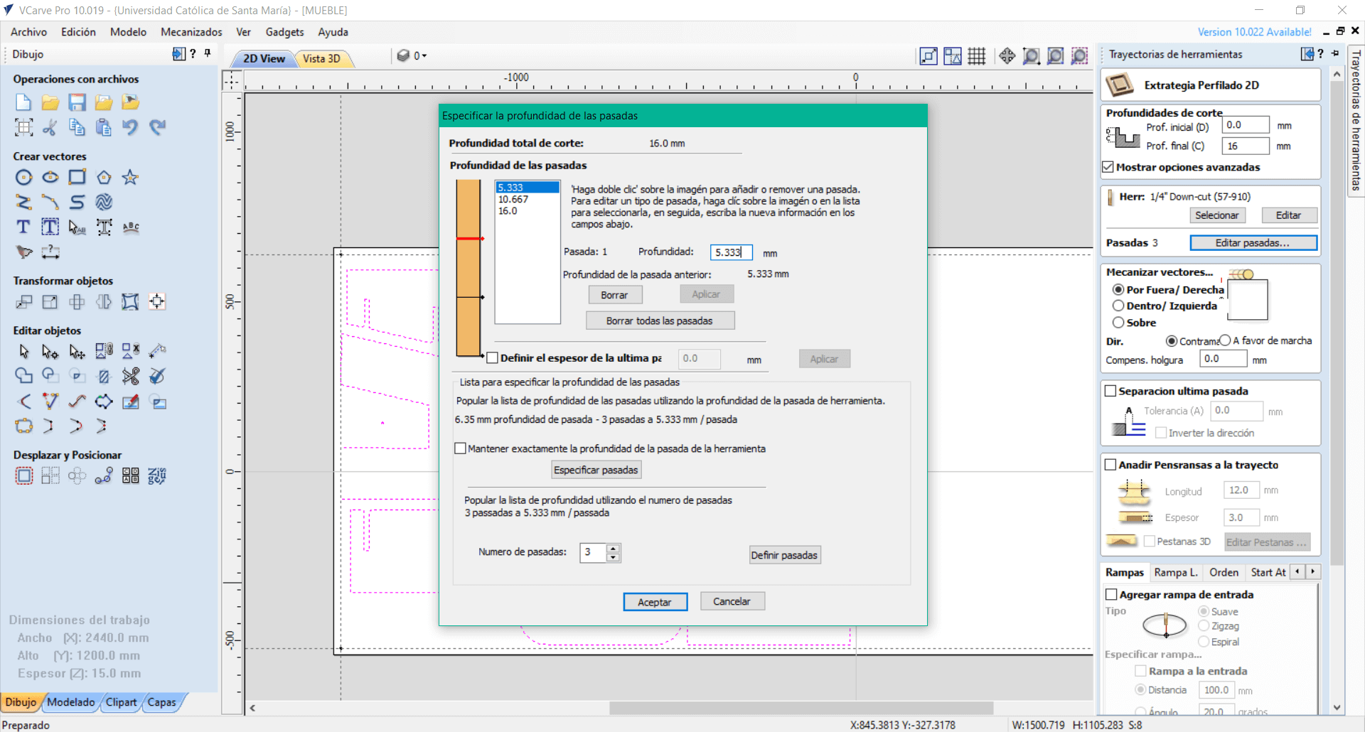
It only remains to define the depth of the passes, our plate is 15mm thick, to make a uniform cut we assign a value of 16mm and according to the software it is recommended to make 3 passes of 5.333mm each, a tip is that the maximum pass depth should not be higher than the diameter of the endmill, ours is 6.35mm, so 5.333mm is in the range of what is allowed.
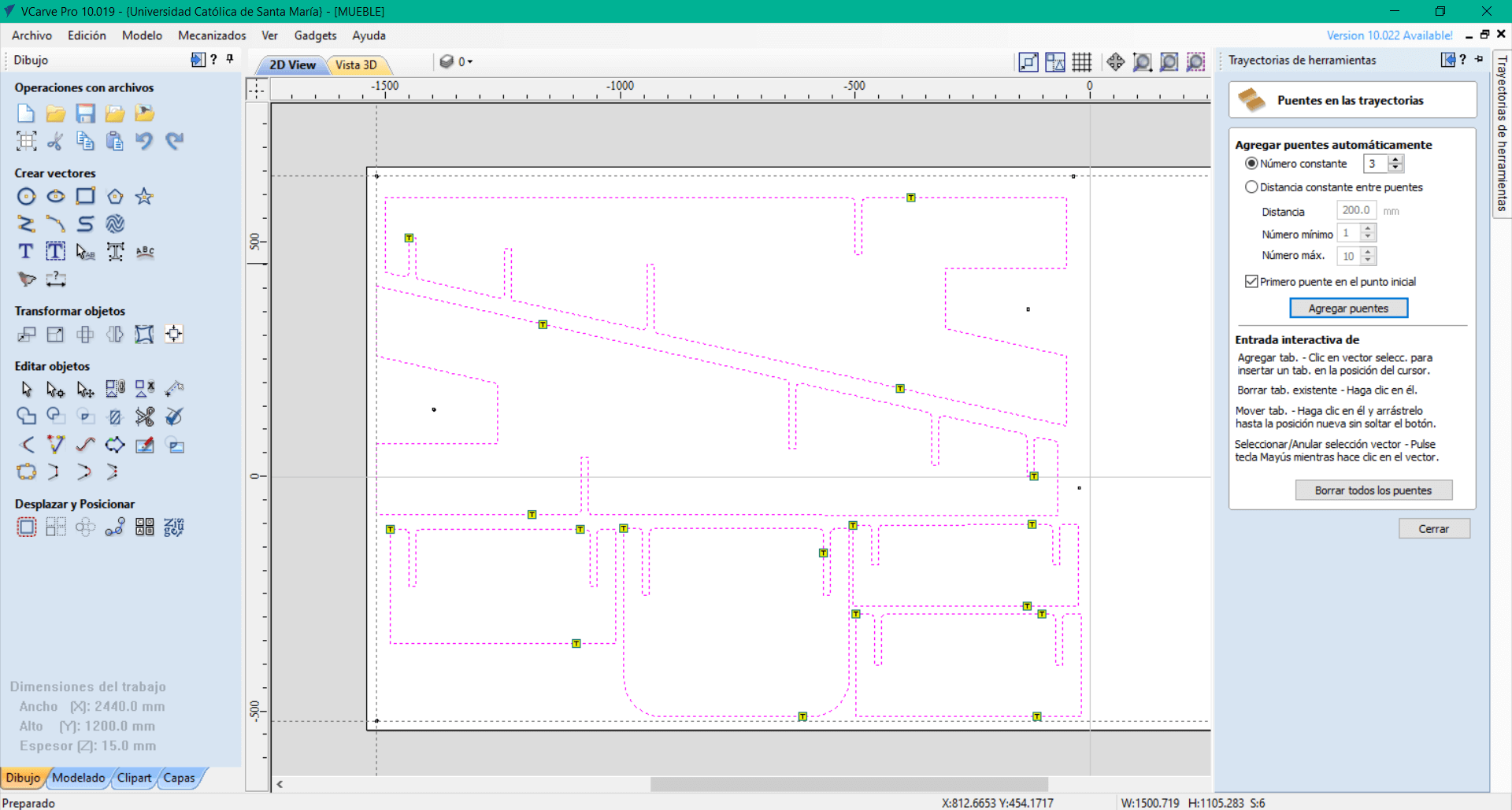
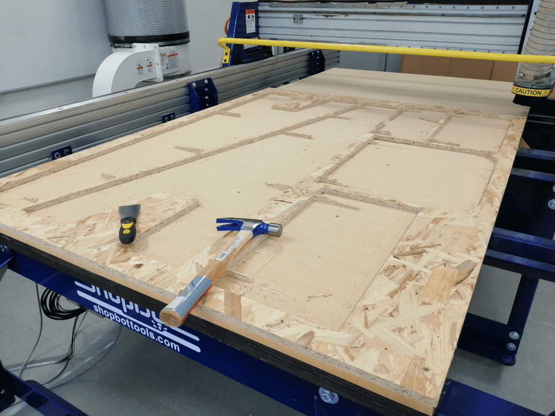
To finish with the cutting toolpaths it is necessary to place tabs to secure the piece to the plate, otherwise the piece will come loose and could cause serious problems both for the machine and for our safety, we just have to activate the tabs option and define the quantity that we want in the piece, I consider that 3 is a good number, at the end of the milling it will be necessary to release the tabs from the plate using a chisel and a rubber hammer.
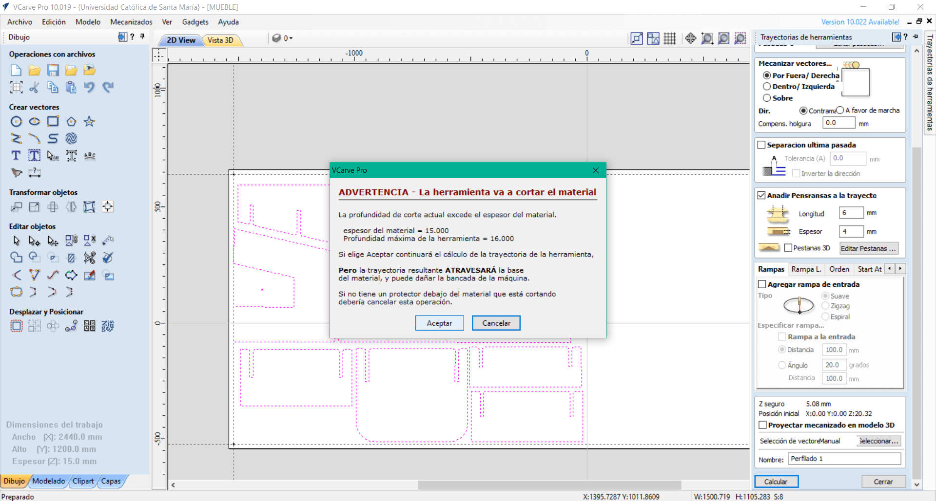
Once all the toolpaths are created, we can calculate all the cuts and see a simulation of the cut, when pressing the calculate button we get a warning that the depth of our cut is bigger than the thickness of the piece, there is no problem since we are aware of that, but it seems to me a very useful warning to be able to give a final review to all the work.
Finally we can run the simulation and check that all our cuts are made as expected, my conclusion is that Vcarve is a very powerful but also user-friendly tool, it was not so difficult to become familiar with the software functions and perhaps I made some errors, but thanks to the feedbacks from my instructor I was able to correct them, we must always keep in mind that when working with large machines it is better to check everything twice to avoid causing accidents.
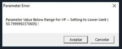
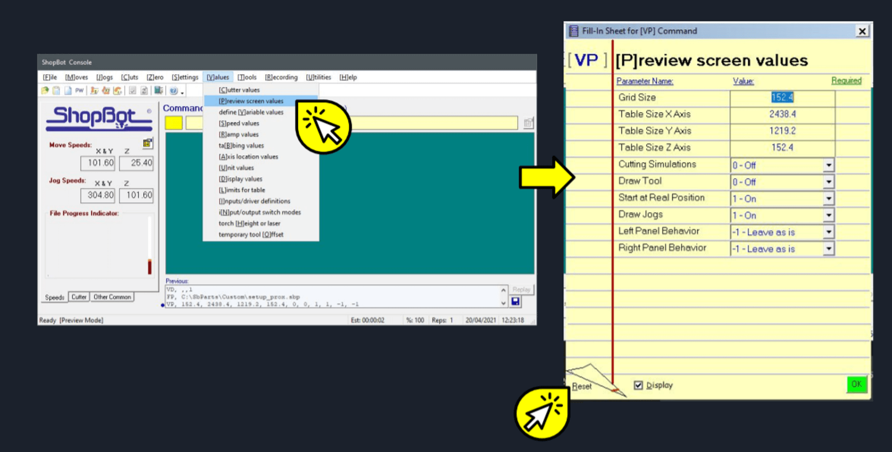
Problem related to Parameter Value VP
Not everything could be perfect, it had been a long time since the last time we used the shopbot and when we decided to use it in this assignment, we had problems with a VP value Below range that we could not understand at the beginning, then we realized that somehow the values of our The machine had been misconfigured, so it was necessary to restart them, we went to the tab [V]alues then to [P]review screen values and in the lower left part of the window we selected the Reset option. After making this configuration, our machine could work correctly and we continued with the development of our assignment.
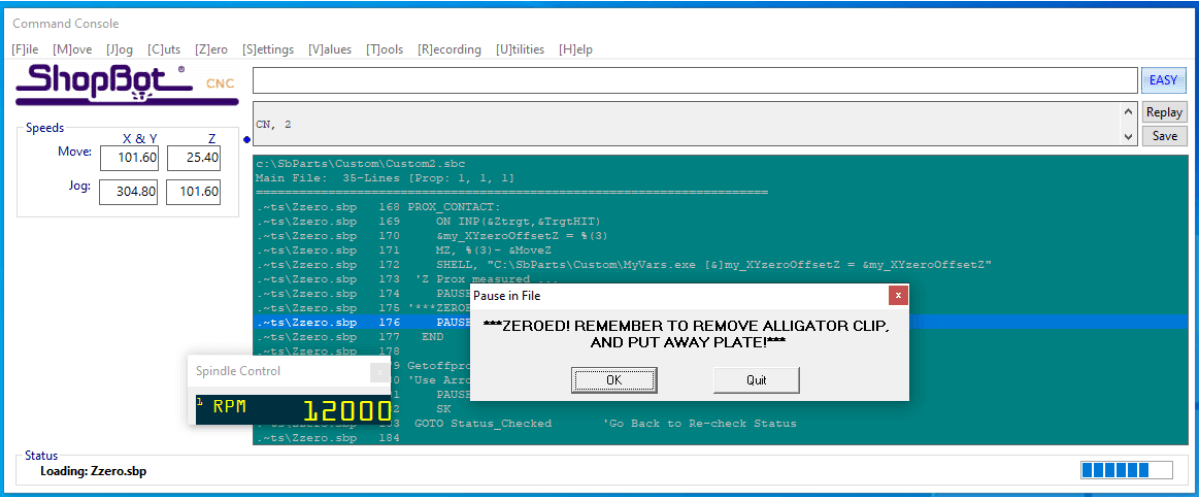
The first thing we must do when opening the shopbot software is to press the reset button, then we must make sure to calibrate our axes, starting with the Z axis, for this we will use the metal plate located on the spindle and the crocodile clips to close a circuit and be able to determine the limit of the Z axis. Then we put everything to its initial position and we can continue calibrating the X and Y axes.
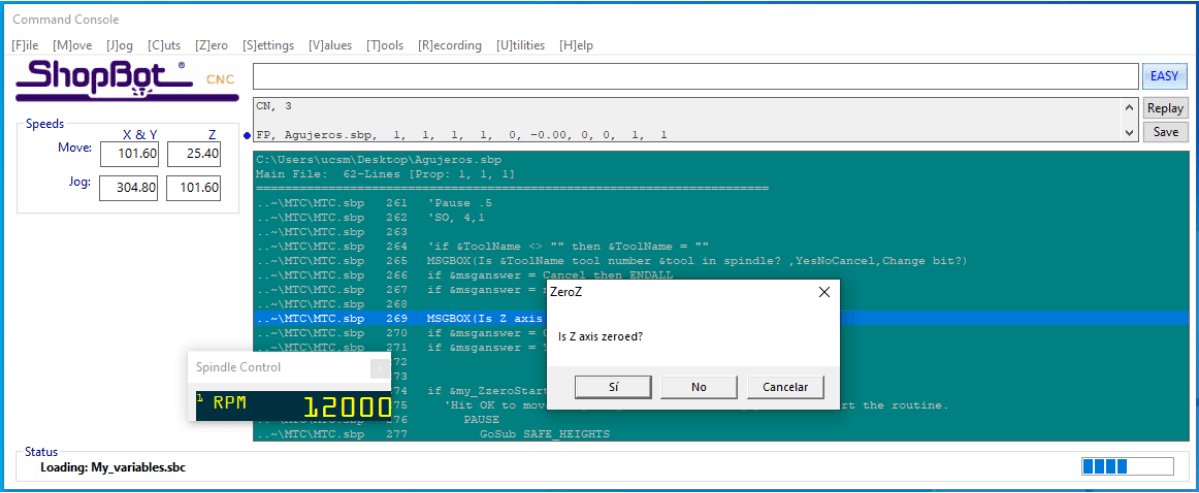
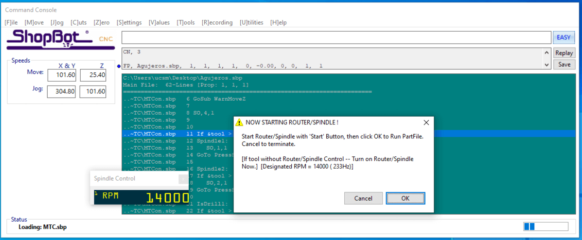
First we must load our toolpaths (holes and cut) to the shopbot software and then continue with the assembly, the holes will be the first to be made and will not pierce the material, they will only leave a mark that we will use as a reference to place the screws with the help of a drill.

Assemble
With the help of a hammer and chisel we can remove the tabs from the pieces and separate them from the OSB sheet, at all times using gloves and glasses, because this material has many splinters and can cause some injuries.
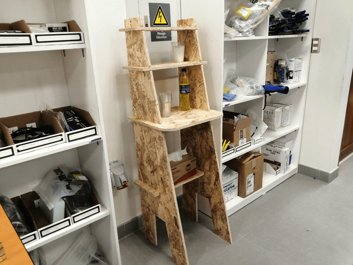
Final Result
As you can see the thickness that we determined of 14.6mm for a 15mm plate worked perfectly, this because when measuring the thickness of the plate we verified that it was not really 15mm but was around 14.6, additionally we rounded the edges and We also use t-bones so that our fits didn’t have any problem.
You can download the files below:
Week Assessment
During this week, have I :
-
[ ] Linked to the group assignment page ? Pending due to access to the laboratory.
-
[ ] Documented how I’ve designed and made my object (something big) ? It was not that difficult to work everything on Inventor, due to the basic shapes of my shelf.
-
[ ] Documented how I’ve made my CAM-toolpath ? I was able to do it from my computer but without being able to export it, I repeated the entire process on the laboratory PC with the Vcarve license.
-
[ ] Documented how I’ve made something BIG (setting up the machine, using fixings, testing joints, adjusting feeds and speeds) ? Pending due to access to the laboratory.
-
[ ] Described problems and how I fixed them ? There is always problems, both in design and in the press fit, but nothing complicated to solve.
-
[ ] Included my design files and hero shots of my final object ? Yes I did, hope someone can use them as a reference.