3. Computer Aided design
This week’s assignment is to model our final project with Computer Aided Design (CAD). We need to experiment with a variety of different types of CAD, including 2D, 3D, rastering, rendering, animating simulating… and more.
But I’m not scared because I trust the amount of information and videos available on the internet to learn how to use these CAD tools in the most appropriate way. I decided that for 2D modeling I would use Inkscape and for 3D Autodesk Fusion 360
Assignment
model (raster, vector, 2D, 3D, render, animate, simulate, …) a possible final project, compress your images and videos, and post it on your class page
Goals
- Learn to use 2D design tools.
- Learn to use 3D design tools.
- Model the parts of my final project.
- Manage to simulate some part of the final project (depending on the progress with 3D modeling)
2D design
The only approach I had related to 2D design was last week to sketch my final project, for which I used Autodesk Sketchbook. So, for this session I chose Inkscape as a 2D design tool because of the amount of videos available (including those from academy). We must first identify the work environment and all the tools available, so that we can then make proper use of them.
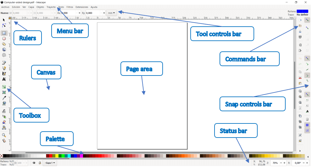
- The application menu bar along the top provides general menu options. Some are similar to other software programs (File ‣ Save, Edit ‣ Copy, etc.). There are also Inkscape-specific items.
- The tool controls bar just below adjusts to the currently selected tool. It displays the tool’s options.
- Vertically on the left, the toolbox contains the main drawing tools. Only one tool can be selected at once.
- The large blank area is the canvas, where the image is edited.
- A black outline represents the visible page area.
- On the right side of the window, there are two toolbars. To the left is the commands bar which gives quick access to common commands, which are also available via the dropdown menus. If not all the commands are shown, there is a right-facing arrow that gives access to the hidden choices.
- To the right is the snap controls bar. We suggest you deactivate snapping for now, by pressing the topmost button in the bar, or by pressing %.
- There are rulers at the top and on the left of the canvas to help with grid and guideline placement.
- Scrollbars are available to the right and bottom to move around on the canvas.
- The color palette is near the bottom of the window. Its most basic usage is to change the fill color of an object.
- At the very bottom, the status bar provides information such as the colors of the selected object, layers, cursor coordinates, and zoom level. It also contains a field where Inkscape can display helpful texts, such as the number and type of selected objects, or tips about keyboard shortcuts and usage hints. Whenever Inkscape doesn’t do what you think it should be doing, look here first.
- Dialogs for specific functionality are available will by default appear attached to the right of the canvas, in the docking area.
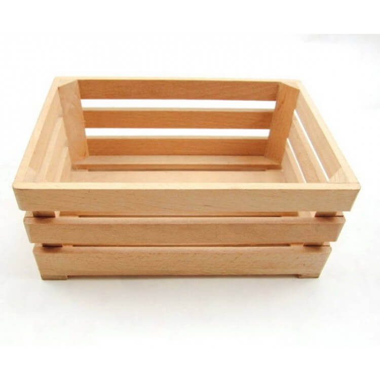
The first piece that I decided to make was the wooden frame of the cart, for that I used as a reference a wooden basket that is normally used to carry fruits.
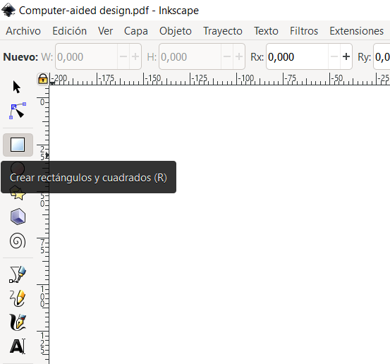
To make this shape I will use the rectangles available in the toolbox
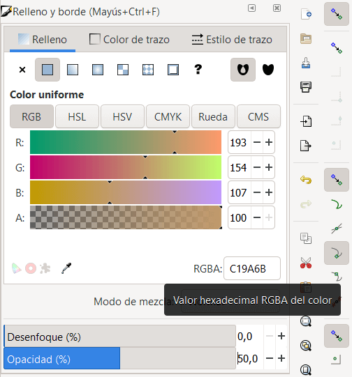
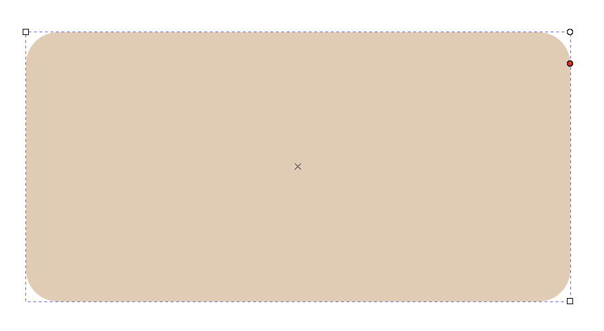
Once the rectangle is created, I will modify the color so to make it look like wood, according to the web the RGB code for the wood is #C19A6B, the Fill and Stroke functions allows us to enter that code specifically and also modify other parameters such as opacity.
To give it a rounded finish we can select the circle located on the edges of the piece and drag the cursor to define the level of curvature.
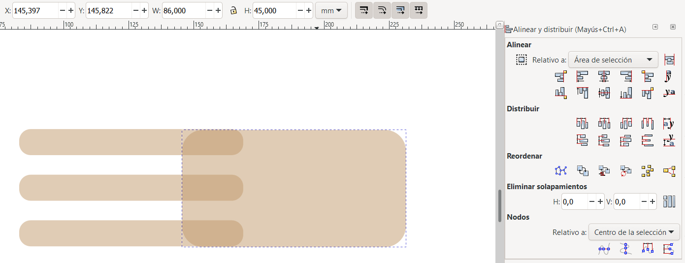
I decided that the size of the basket would be 45cm high with pieces of wood 10cm high by 86cm long, the alignment tool was very useful to help me distribute the wooden boards evenly and centrally.
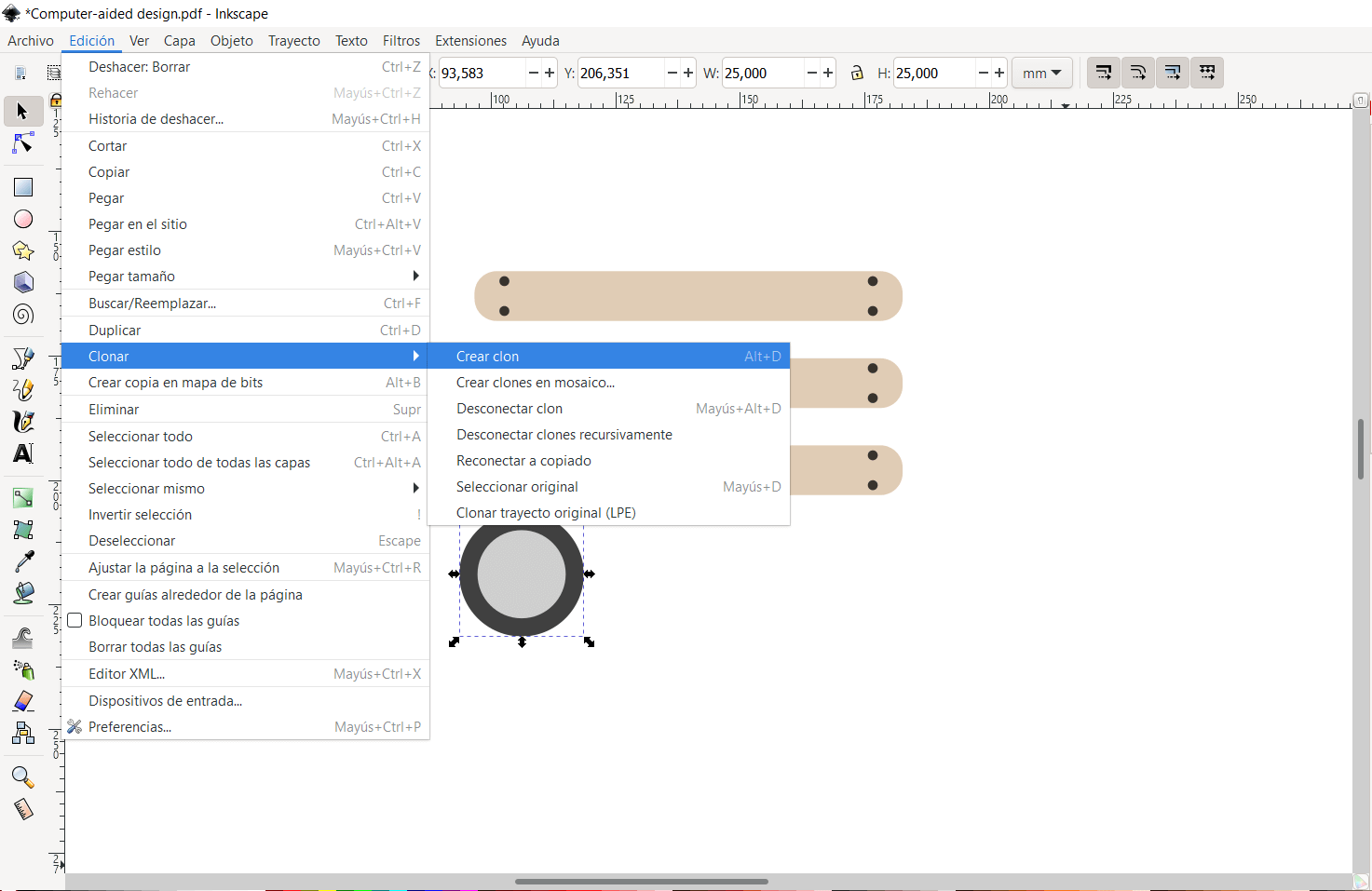
Neil also talked about an option that I found super useful, which is to clone a piece, which allows modifying the physical characteristics of a piece and in the same way affects the clone, later it will be seen that when a clone is grouped, it loses dependence on the other part and the changes are no longer made.
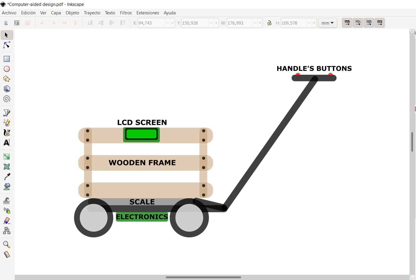
With all those tools and other ones like adding texts, rotating shapes, inserting circles, etc. I was able to finish the modeling of my final project, very similar to the sketch I had in mind, but this time closer to reality, since the measurements entered were those of a real cart (https://www.walmart.com/ip/Gorilla-Carts-GOR400-400-lb-Steel-Mesh-Garden-Cart-with-10-Tires/50753941) with a capacity of 3 CU FT, a capacity very close to my requirements. I have grouped all the shapes together so I can move the finished model.
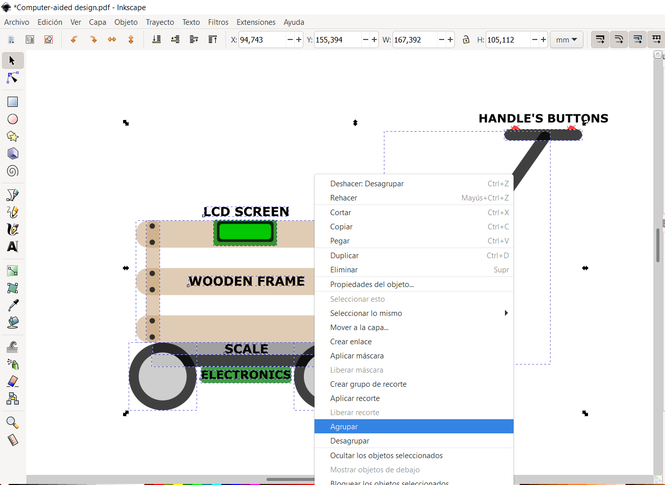
Here you can see the finished model with the detailed and marked parts.
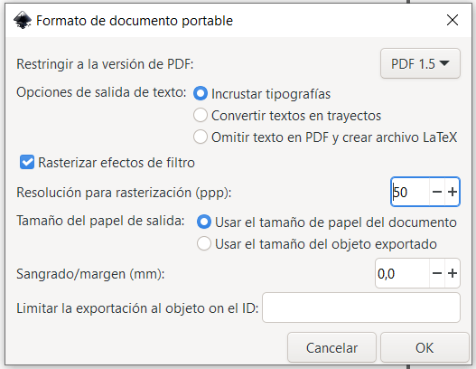
Finally I decided to export the design in 2 ways, one as PDF and the other exporting the image as PNG
3D design
My knowledge of 3D design is limited, at university I used tools like Autocad and Inventor but in a very basic way, I also used Tinkercad to make simple designs and make some basic modifications to stl files, my goal for this session is to learn how to use Autodesk Fusion360 to be used in a mandatory way in all the projects that I will develop in the future (the information available on the internet gives me the confidence to be able to fulfill this task). Autodesk Fusion360 has an infinity of tools for modeling, I will try to use as many as possible to be able to simulate my final project, but first it is necessary to identify the work environment and the available tools.
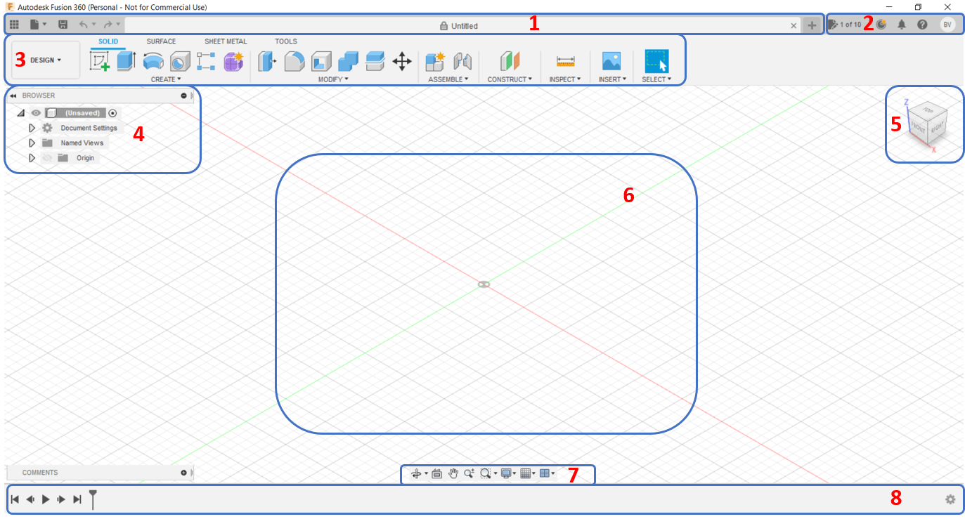
- Application Bar: The Application Bar is located in the upper left-hand corner. Within the application bar, there are 4 key areas.
- Data panel: Houses your design files.
- File menu: Create, export, or share your designs.
- Save: Save your designs along with version descriptions.
- Undo and Redo buttons: To revert your most recent actions.
- Profile and Help:
- Notification Center: Notifications will appear (a few times a year) with important notices, such as planned maintenance.
- Job Status: View job status, Fusion 360 update status, and online/offline status.
- Profile: Click your name to:
- Access your Autodesk Account
- Adjust your Fusion 360 preferences
- Switch between teams
- View or edit your profile
- Sign out
- Toolbar: The toolbar allows you to select what type of workspace you would like to work in. It’s important to note that the tools on the toolbar will differ in each workspace. Within each toolbar, there are also tabs, which further organize the tools into logical groupings. As you start to discover your own common workflows you can customize and rearrange your toolbar features.
- Browser: The browser lists objects in your design, including planes, sketches, parts, assemblies, and so on. You can think of the Browser as your file structure. Within the browser, you can change the visibility of objects as well as change your document units.
- ViewCube: The viewcube allows you to orbit your design or view the design from standard view positions. You can either select faces, corners, or the arrows, or you can simply click and drag the viewcube around. You can also hit the home icon, which is next to the viewcube, to view the model in the default home position.
- Canvas: The middle section of Fusion 360 is where you’ll be doing sketching and doing all of your design work. Therefore, this section is referred to as the canvas. Within the canvas, you can access the “marking menu,” which is also referred to as the right-click menu. If you right-click you’ll see frequently used commands, along with the ability to change workspaces, without having to go to the upper left corner.
- Navigation Bar and Display Settings: The navigation bar contains commands used to zoom, pan, and orbit your design. These options will give you a little bit more control over the use of the viewcube. The display settings control the appearance of the interface. You can change the environment style (color), you can turn on and off ground shadows and other effects, turn grids on or off, or view your design from multiple views at once.
- Timeline: The timeline lists the order of operations performed on your design. Double-click on timeline features to quickly edit their properties. You can also right-click operations to make additional changes. Because Fusion 360 is a parametric modeling program, you can also drag the operations around to change the order they are calculated. However, you’ll want to be very careful as changing the order can also cause errors or problems with your model.
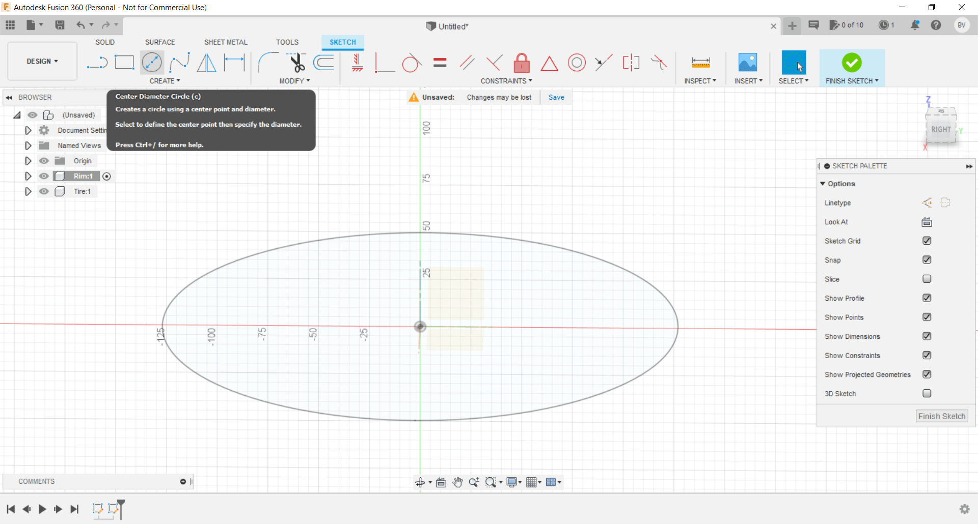
The first thing we need to do is create a new component, in this case I will start with the rim and the tire.

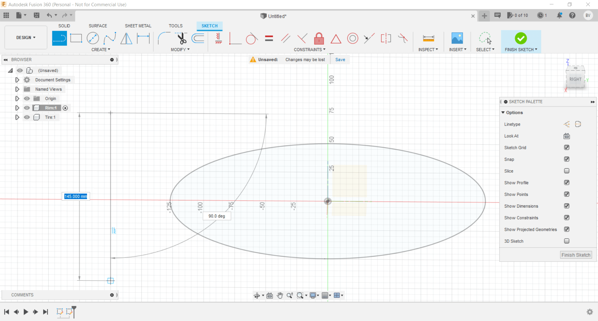
Then I am going to use the tool to create a circle as a reference of the diameter of my wheel that will be 10 inches, turning it to millimeters it will be approximately 250mm.
I will create a perpendicular line to the circle as a reference to define the thickness of the tire, which will be 145mm, using the coincident option I can align it with the center of the circle.
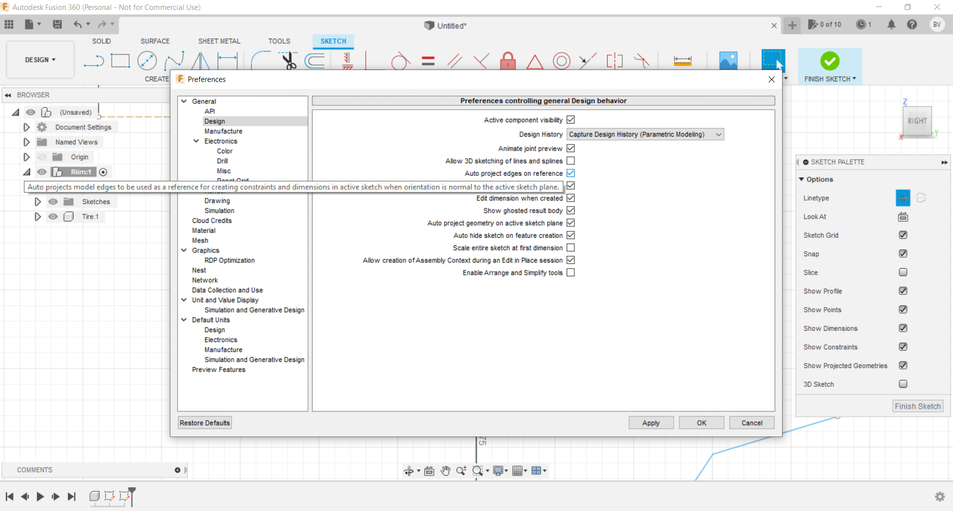
It is important to enable the Auto project edges and references option, to be able to join the sketches made in different axes.
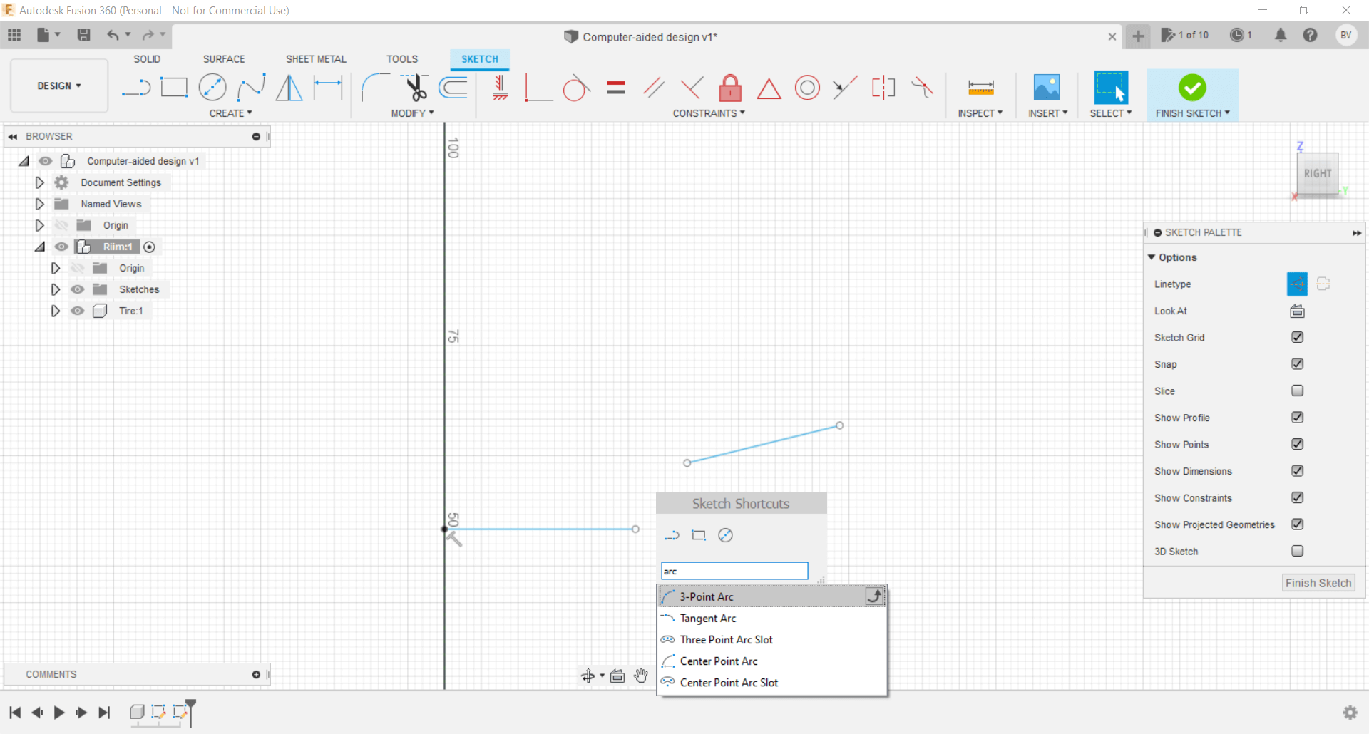
To make the internal shape of the ring I will use lines and 3-point arches, now it is easier since the S button allows me to quickly search for these and many more options
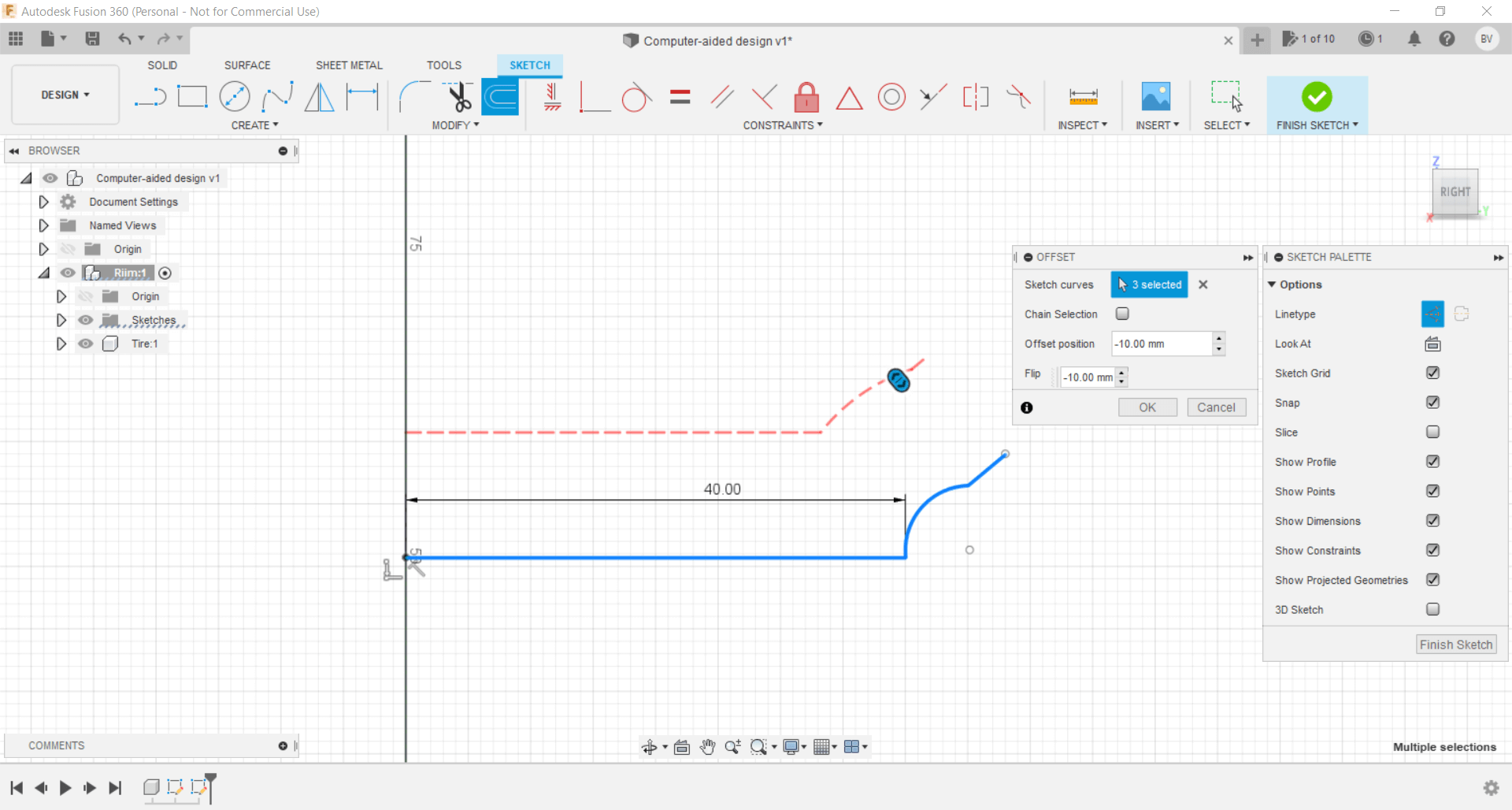
Using the offset tool I can define the thickness of my piece, in this case will be 10mm, I am not very sure of the real measurement, but I feel that it is an adequate value, also this first design is only a model of the final project idea, As the sessions progress, I will refine more the design
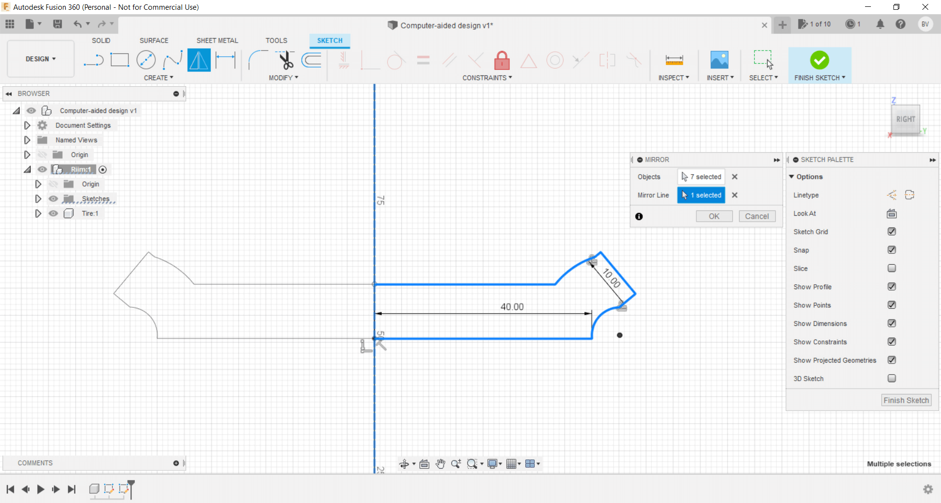
It is necessary to close the shape and also with the mirror option to reflect the piece according to the Y axis resulting in a cut view of the ring
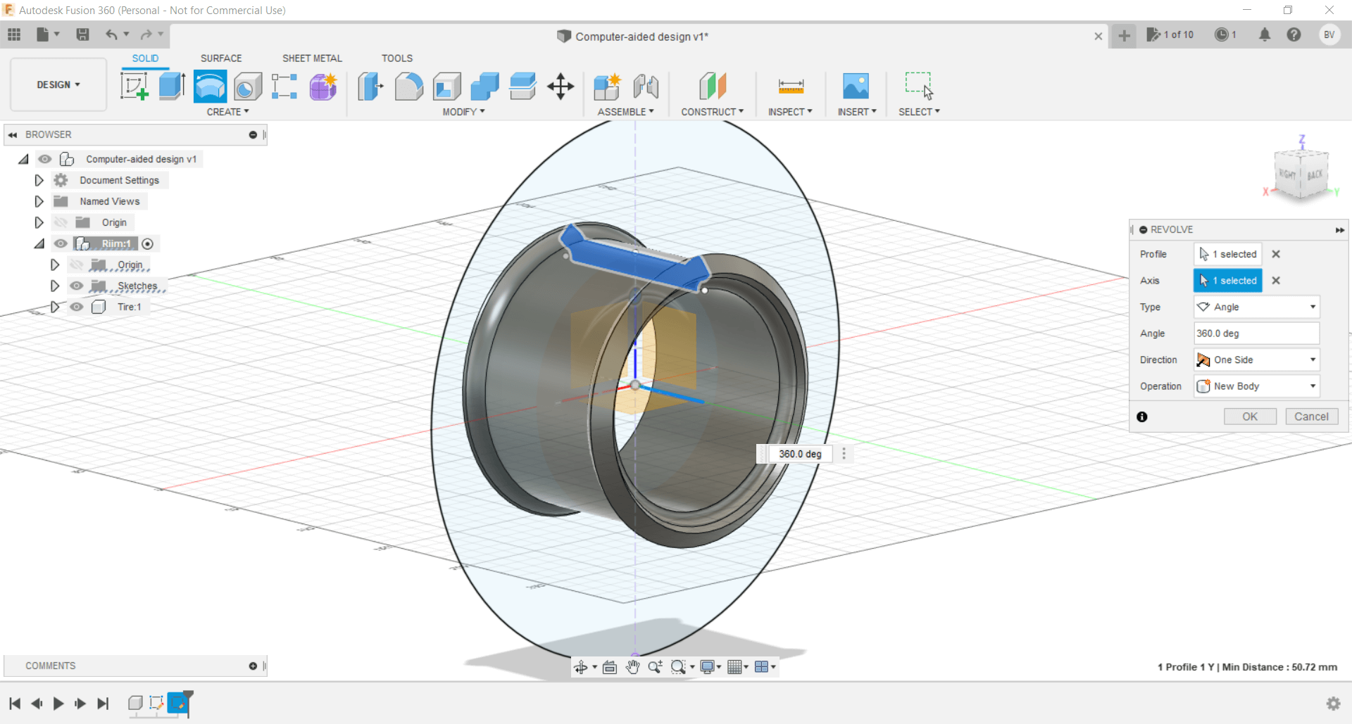
I found the revolve option super useful as I transform my design from 2D to 3D by rotating it in relation to the X axis
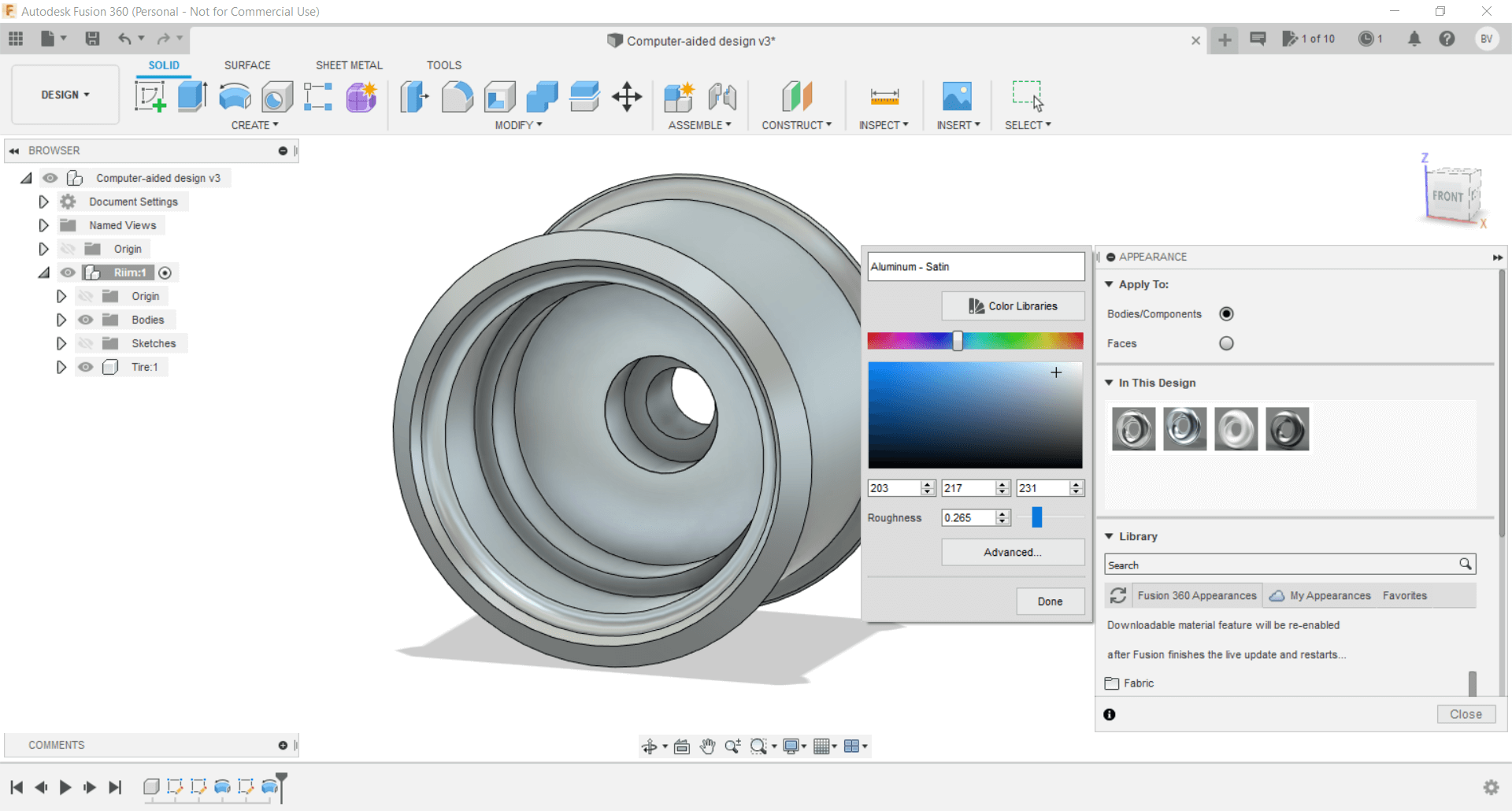
I consider that the options used previously will be more than enough to finish designing my model, finally the Appearance option allows me to define the material of the piece that I just created, I decided to use aluminum for the rim and rubber bumpy for the tire.
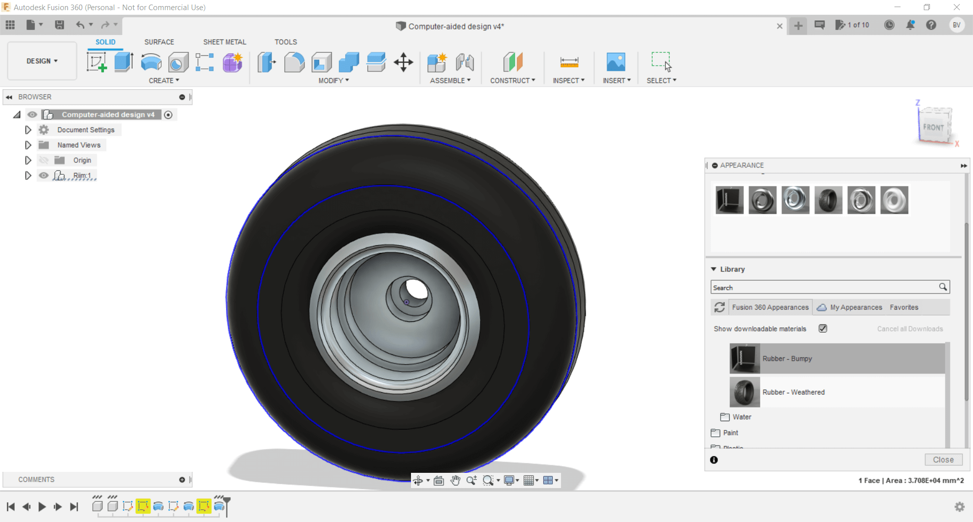
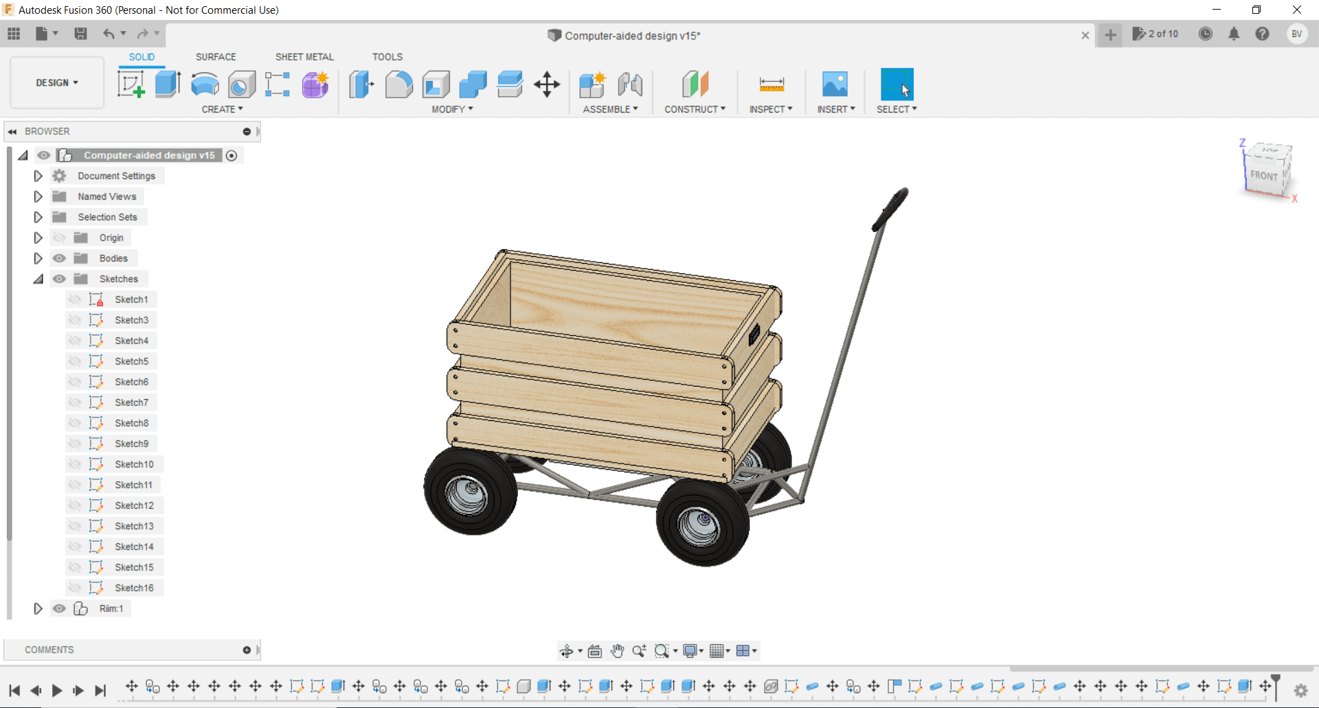
After several hours dedicated to Fusion360 I was able to finish with the design of my final project, I consider that I will make some changes later, but this 3D model helped me a lot to be able to make some measurements that I had in mind and also to clarify my idea.