4. Computer controlled cutting
This week’s assignment consists of using the computer-controlled cutting tools, we refer to the vinyl cutter and also the laser cutter, on previous occasions I did cutting work in 3mm MDF, but I never went into the necessary steps to perform the task, since I only gave the file to a company who provided the service, so I consider this week’s assignment as an opportunity to understand in detail the operation of the machines and to determine the best parameters to use them.
Assignment
group assignment:
- characterize your lasercutter’s focus, power, speed, rate, kerf, joint clearance and types.
individual assignment:
- cut something on the vinylcutter.
- design, lasercut, and document a parametric construction kit, accounting for the lasercutter kerf, which can be assembled in multiple ways, and for extra credit include elements that aren’t flat.
Group assignment
Before starting with the individual assignment, it is necessary to characterize our laser cutter machine, this will help us to make the most of the machine for the jobs we do later.
It is important to try different materials to identify how they behave in the laser cutter, the good thing is that the same template can be applied to all, searching on the internet I found this template that seemed very complete, it even comes with instructions https://www.thingiverse.com/thing:2243854
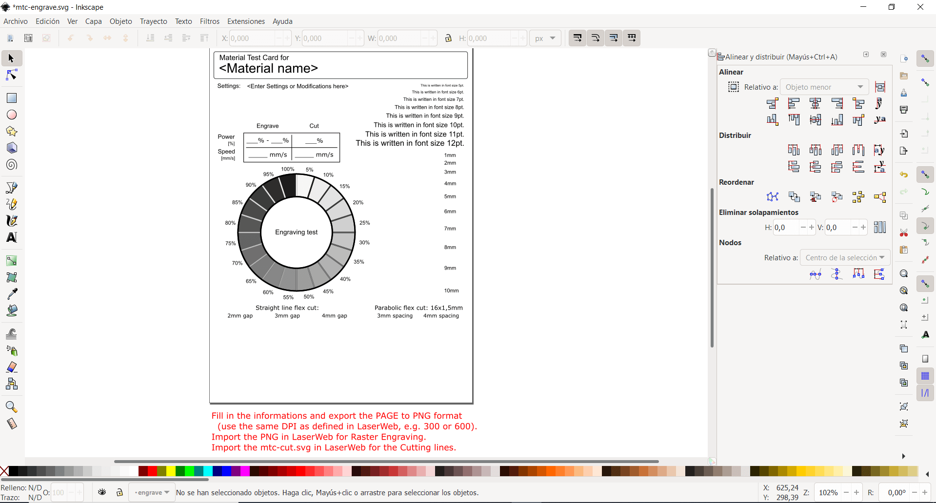
The steps to prepare the files are relatively easy:
-
Prepare the files to be cut, exporting the files in the appropriate format, the advantage of Inkscape is that it directly allows us to send the file to print.
-
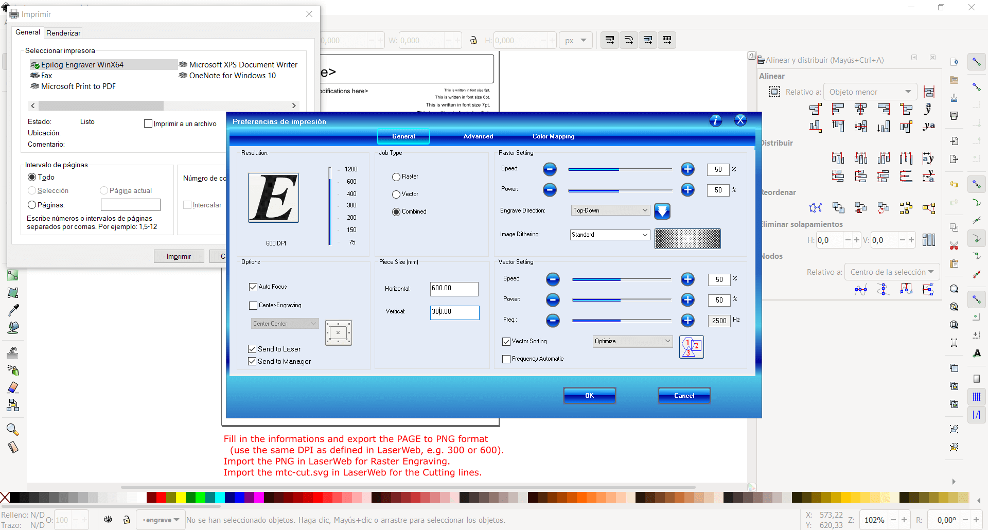
The important part is to characterize the following parameters:
- Speed
- Power
- Type of cut (cut, engrave or raster)
- Important Set the size of the workspace and also enable Autofocus
I found a super useful list of the most important parameters for each of the materials courtesy of Nil Peguero, that will be the one we will use to characterize the materials:
Material settings: Power (P), Speed (S), Resolution (R)
MDF (2.5 mm)
- Cut: P 55 / S 0.5 / R 1000Hz
- Engrave: P 70 / S 100 / R 1000Hz
- Raster: P 80 / S 50 / R 1000 PPI
Transparent Acrilic (3 mm)
- Cut: P 60 / S 0.5 / R 20000Hz
- Engrave: P 70 / S 100 / R 20000Hz
- Raster: P 60 / S 100 / R 1000PPI
Plywood (4mm)
- Cut: P 75 / S 0.5 / R 1000Hz
- Engrave: P 65 / S 100 / R 1000Hz
- Raster: P 60 / S 100 / R 1000PPI
Individual assignment
Cut something on the vinyl cuter
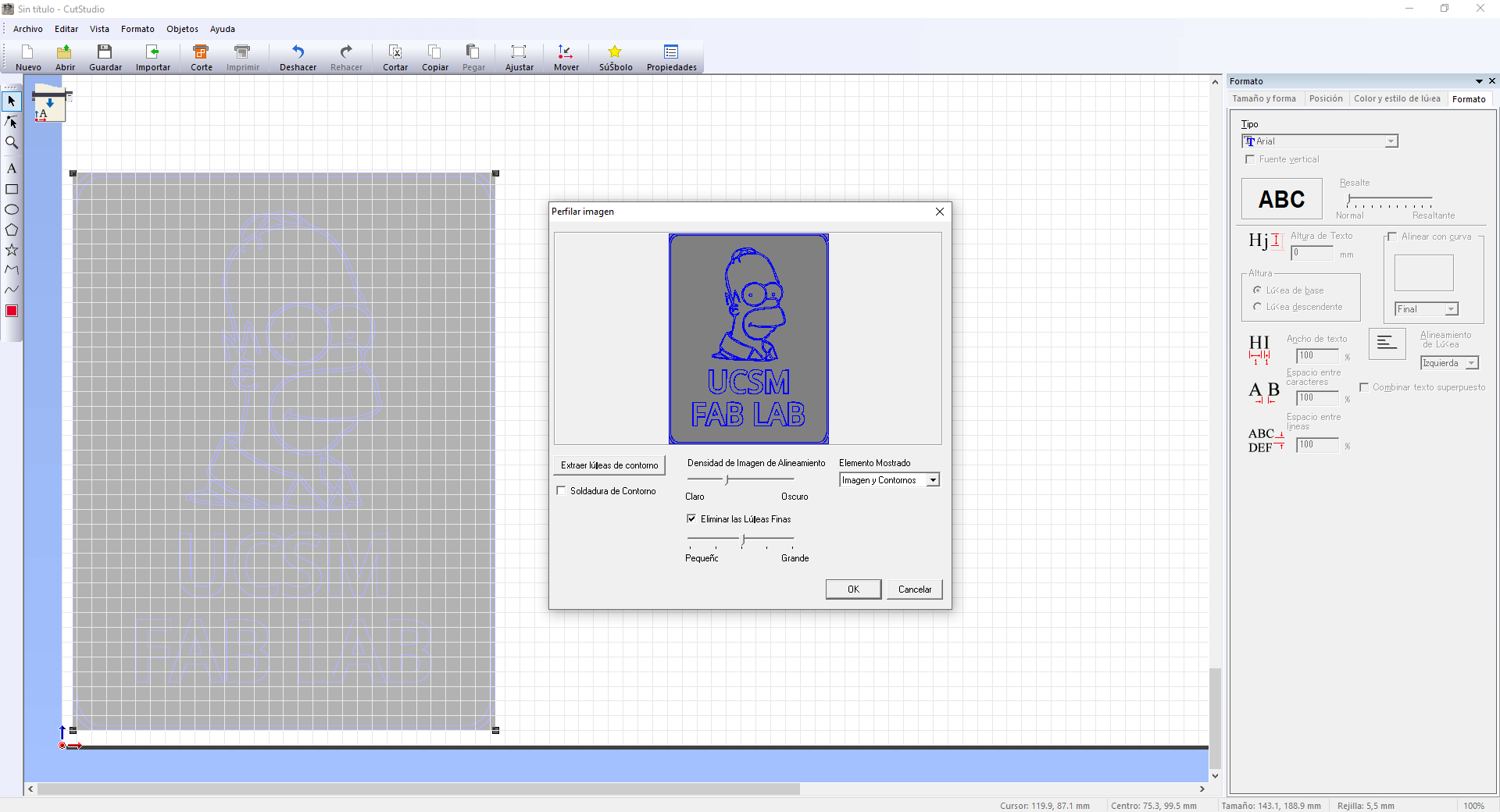
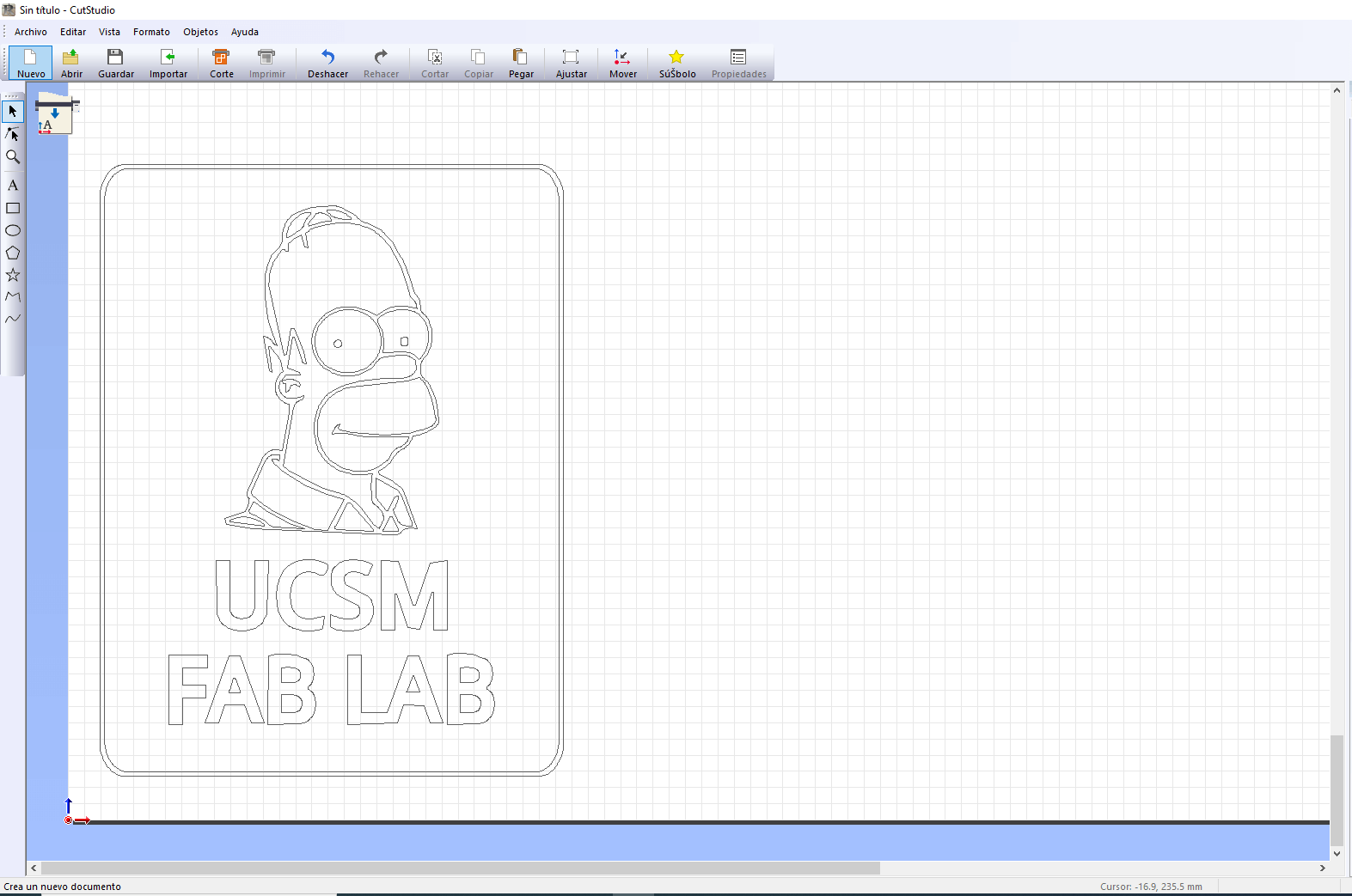
Vinyl cutting always seemed interesting to me, although sometimes I made that type of cuts I always needed a file with the extension .svg but for this work we will start from an image that I will process in Inkscape and then we will enter to the Roland software to give it the finishing touches. I have selected the image of Homer Simpson, with the identification of UCSM FAB LAB due the laptop is black color, the cut will be made in white vinyl.
Once the final shape is defined, we can export the image to enter it into CutStudio, the tool that Roland offers us to process the files for cutting, the first thing we must do is extract the contour lines to establish only the pieces that are going to be cut, in this case what we wanted was to have a slim silhouette of Homer.
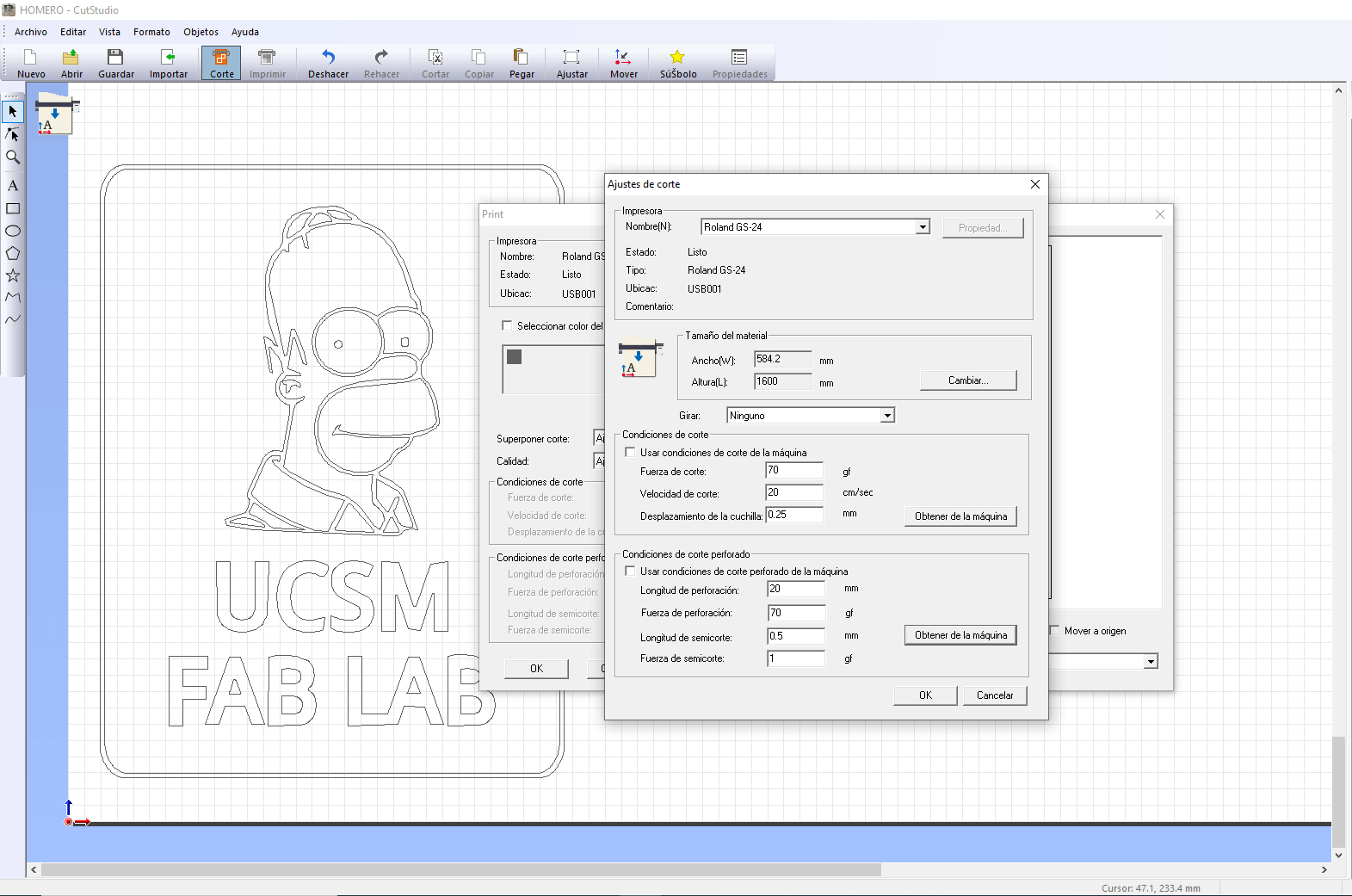
Finally, we must define the appropriate cutting parameters for the machine that we are going to use, the most important thing is the width of the sheet, the cutting force and the cutting speed. With all that defined, all you have to do is press the print button and start cutting.
Material size
- Width: 584.20 mm
- Height: 1600 mm
Cutting conditions - Cutting force: 70 gf - Cutting speed: 20 cm / sec - Blade offset: 0.25 mm
Perforated cut conditions - Drilling length: 20 mm - Piercing force: 70 gf - Half-cut length: 0.5 mm - Half shear force: 1 gf
It is important to emphasize that these values were obtained from the machine by pressing the button located on the right side of each tab (get from the machine) and they worked correctly and smoothly.
The design chosen had some complications by the very small parts to work, for example the thickness of the silhouettes and the eyes of Homer, because they stayed glued in the vinyl in hardly adhered to the transfer.
After cutting the vinyl I removed the parts of unwanted material and then overlaid on the transfer adhesive material, finally it was adhering to the laptop.
Parametric 2D modelling
I had never heard of parametric design before and since I saw Neil’s example last class I was very interested in the variety of applications that can be given to designs, especially for this class since I can assign a variable to determine the thickness of joints depending on the material.
Since my final project was developed in Fusion360 I decided to continue using this tool, as always helped by a YouTube video tutorial, in this case I found a video by Joseph Prusa that explained in a very simply way what parametric design was in Fusion360 and I decided to just use that for reference, assuming it would be easy to implement.
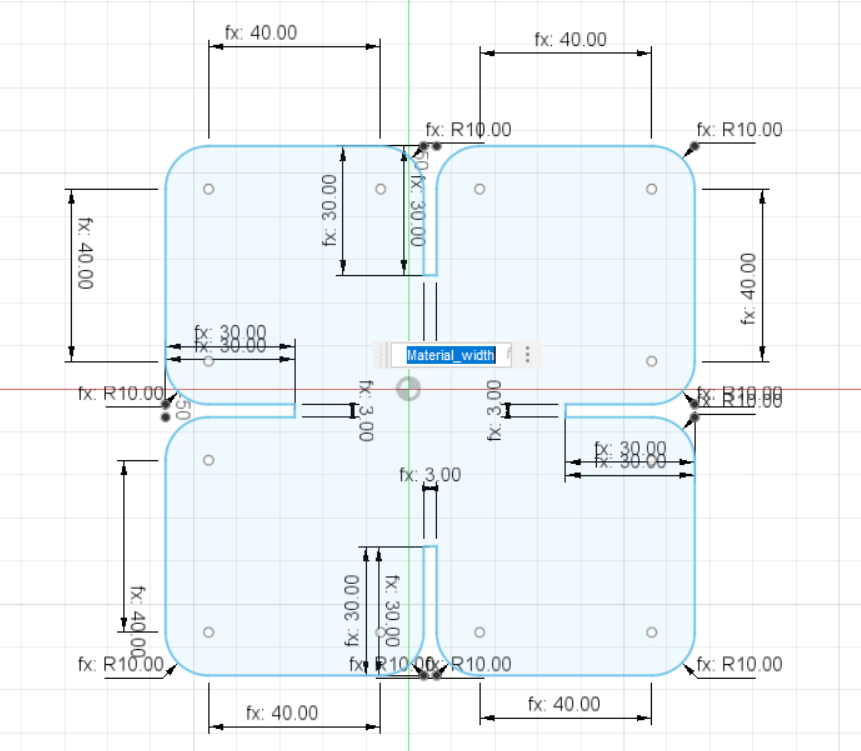
I started with the basics, which is to draw the shape of the piece that I will use for the parametric kit, for that I created a sketch and began to draw the basic shape of my piece with lines, with the shape already defined I went to the Modify tab to select the Change Parameters option and define variables that I will then assign to certain parts of the design.
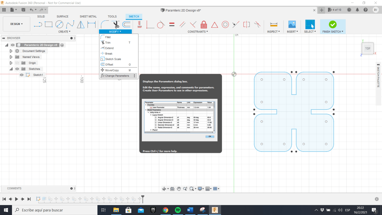
For example, create the variable Material_width as its name says, it will be in charge of determining the thickness of the material and it will serve me for the joints and also to extrude when simulating the pieces, one way to identify a parametric measure is through the symbol Fx that automatically appears next to the measure.
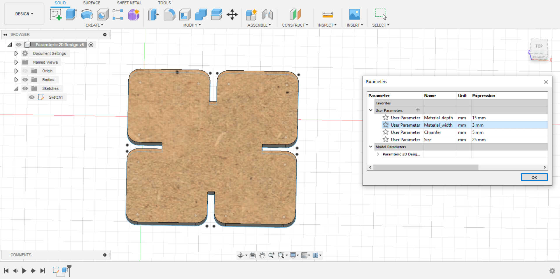
The only thing left pending was to extrude the piece and start playing with the measurements to see how the piece changed almost instantly based on the values that I entered in the parameter window, I also chose the MDF appearance to have a better idea. close to what the final product would be.
The parameters that I modified were:
- Material_depth: It defines the size of the join.
- Material_width: It defines the thickness of the material.
- Chamfer: Neil also talked about the way that part join, so I took that into consideration.
- Size: It defines the size of the square part.
The parts were exported in DXF so that they could later be imported into Inkscape and started cutting.

Kerf = Width
Kerf is defined as the width of material that is removed by a cutting process. It was originally used to describe how much wood was removed by a saw, because the teeth on a saw are bent to the side, so that they remove more material than the width of the saw blade itself, preventing the blade from getting stuck in the wood.
Kerf width is a measure of how much material is removed. When talking about CNC shape cutting with typical cutting processes, kerf is the width of material that the process removes as it cuts through the plate.
How kerf offset is adjusted
Kerf offset is traditionally adjusted by the machine operator at the CNC. Prior to running a program, the operator must enter the kerf width so that the CNC can calculate the actual tool path required to cut the part to the correct dimensions.
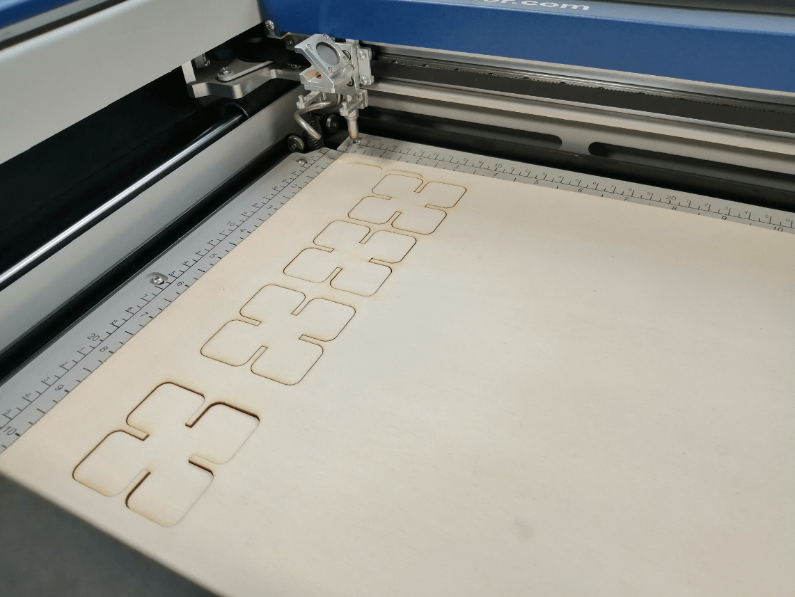
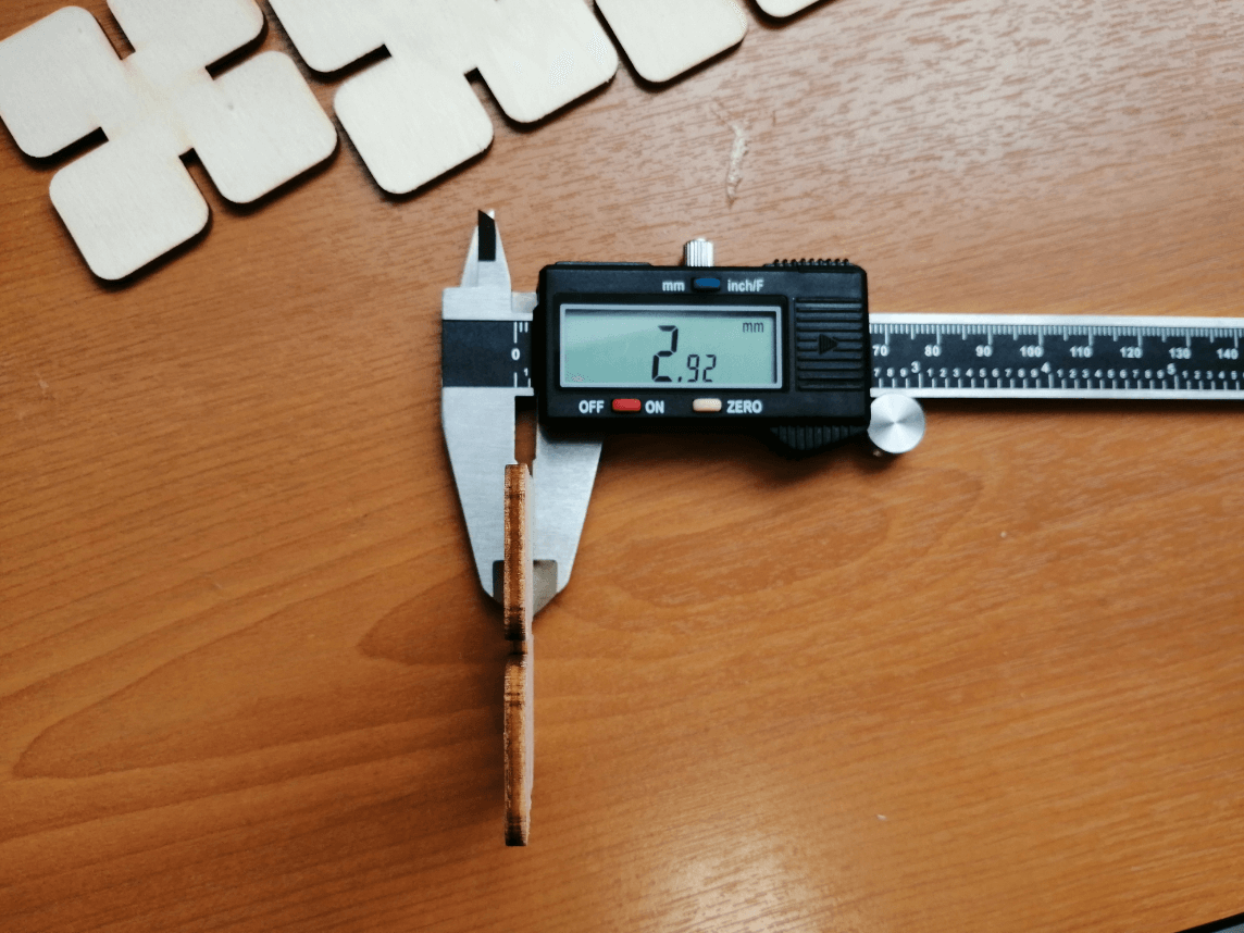
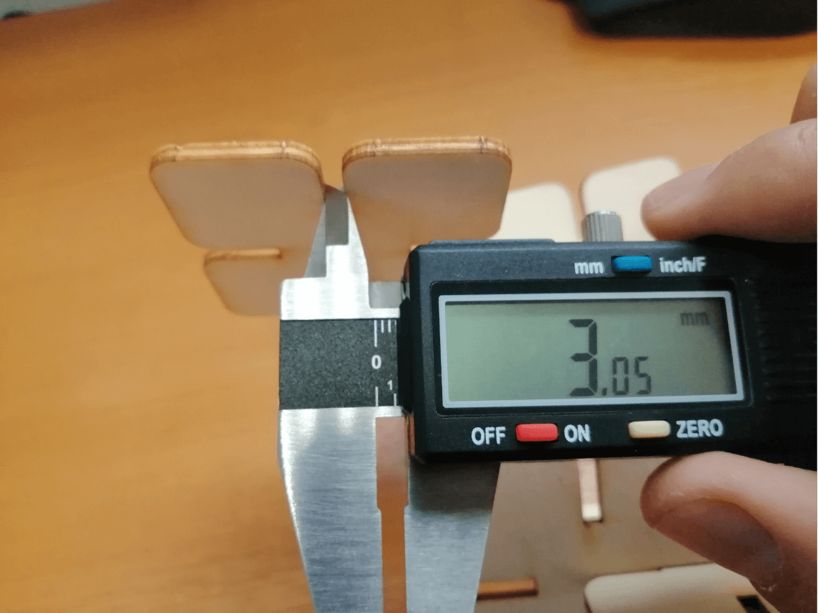
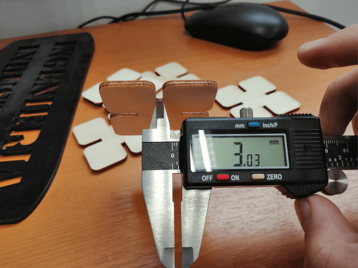
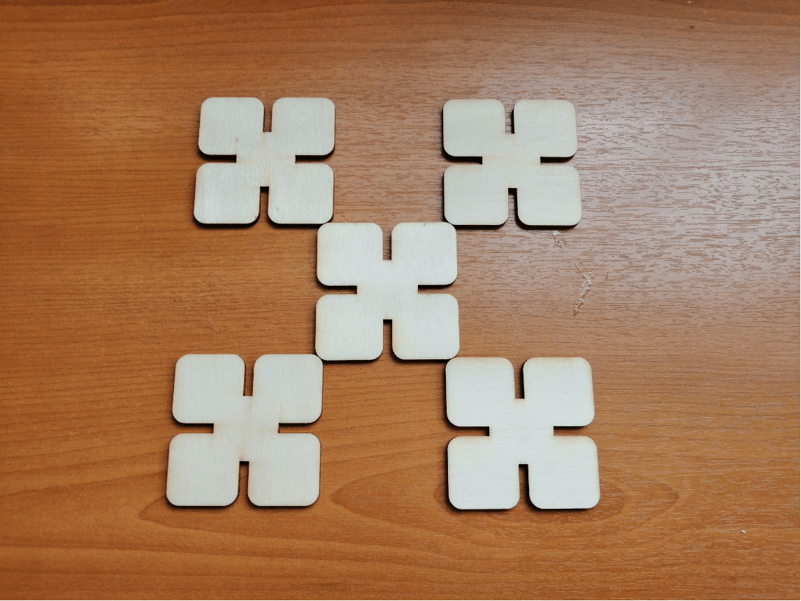
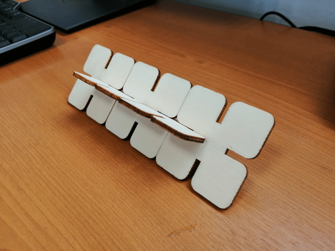
Our laser cutter behaved as expected and we were able to fit our press fit kit without any problem (too wide or too thin) as shown in the images below. Something important is that the wooden plank we used should be 3mm thick, but when making the measurement we found that it was actually 2.9mm in some parts, We were able to identify it in time and we located the part with 3mm thickness to make the cut.
You can download the files below:
Lasercutter’s template .svg files:
Parametric design files:
Week Assessment
During this week, have I :
-
[ ] Linked to the group assignment page ? Yes, I did.
-
[ ] Explained how I parametrically designed my files? Yes, have a look at the Parametric 2D modelling.
-
[ ] Documented how I made my press-fit kit ? Sort of, because we are currently in mandatory social isolation due to covid-19, I could’nt make the cuts, but I did generate the files.
-
[ ] Documented how I made my vinyl cutting ? Yes, my Homer Simpson sticker proves it.
-
[ ] Included my original design files ? I hope I have solved the problem when uploading the files.
-
[ ] Included my hero shots ? Not yet, I am waiting to mandatory social isolation to finish to be able to run all the tests.