14. Networking and Communications
This week’s assignment consists of establishing communication between 2 boards, either wired or wireless using a communication protocol, due to the short time I have, I will apply an ingenious solution and enable the first version of the board that I use (with some faults fixed) to be able to communicate both and turn on an off a led.
Assignment
group assignment:
- send a message between two projects.
individual assignment:
- design, build, and connect wired or wireless node(s) with network or bus addresses.
Group assignment
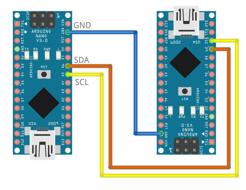
As an extra node I decided to add an Arduino UNO (master mode) and configure my 2 boards as secondary, with the variation depending on the character that is sent through the serial bus, in order to turn on the LEDs of each of the boards in cascade with a delay of 1 second between each of them. The wiring was easy and it was only necessary to share GND between the 3 boards and assign 2 pins for serial communication 5 as Rx and 6 as Tx.

Master code (Arduino UNO)
#include <SoftwareSerial.h>
SoftwareSerial mySerial(5, 6); // RX, TX
const int led = 13;
int buttonState = 0;
int value = 0;

void setup() {
  mySerial.begin(9600);
  pinMode(led, OUTPUT);
}

void loop() {

    mySerial.print('1');
    delay(1000);

    mySerial.print('2');
    delay(1000);

    digitalWrite(led, HIGH);
    delay(1000);
    digitalWrite(led, LOW);
    delay(100);
}
Secondary code (Board 1)
#include <SoftwareSerial.h>
SoftwareSerial mySerial(2, 0); //RX, TX
const int boton = 3;
const int led = 1;
int buttonState = 0;
int value;

void setup() {
  mySerial.begin(9600);
  pinMode(led, OUTPUT);
  pinMode(boton, INPUT);
}

void loop() {
  value = mySerial.read();
  if (value == '1')
  {
    digitalWrite(led, HIGH);
    delay(1000);
  }

  else
  {
    digitalWrite(led, LOW);
  }
}
Secondary code (Board 2)
#include <SoftwareSerial.h>
SoftwareSerial mySerial(2, 0); //RX, TX
const int boton = 3;
const int led = 1;
int buttonState = 0;
int value;

void setup() {
  mySerial.begin(9600);
  pinMode(led, OUTPUT);
  pinMode(boton, INPUT);
}

void loop() {
  value = mySerial.read();
  if (value == '2')
  {
    digitalWrite(led, HIGH);
    delay(1000);
  }

  else
  {
    digitalWrite(led, LOW);
  }
}
Final Result


Individual assignment:
This week I decided to focus entirely on communication protocols, so I enabled the first version of my board never used in the previous assignments, this one, unlike the current one, works with an ATtiny45 and as you can see, it also suffered some extra cuts at the time of milling. So I didn’t use it, but I managed to give it a little love and interest and it worked perfectly like my other board.


What I learned from Software serial
The SoftwareSerial library has been developed to allow serial communication on other digital pins of the Arduino, using software to replicate the functionality (hence the name “SoftwareSerial”). It is possible to have multiple software serial ports with speeds up to 115200 bps. A parameter enables inverted signaling for devices which require that protocol. To use this library #include
The library has the following known limitations:
- If using multiple software serial ports, only one can receive data at a time.
- Not all pins on the Mega and Mega 2560 support change interrupts, so only the following can be used for RX: 10, 11, 12, 13, 14, 15, 50, 51, 52, 53, A8 (62), A9 (63), A10 (64), A11 (65), A12 (66), A13 (67), A14 (68), A15 (69).
- Not all pins on the Leonardo and Micro support change interrupts, so only the following can be used for RX: 8, 9, 10, 11, 14 (MISO), 15 (SCK), 16 (MOSI).
- On Arduino or Genuino 101 the current maximum RX speed is 57600bps
- On Arduino or Genuino 101 RX doesn’t work on Pin 13
- If your project requires simultaneous data flows, see Paul Stoffregen’s AltSoftSerial library. AltSoftSerial overcomes a number of other issues with the core SoftwareSerial, but has it’s own limitations. Refer to the AltSoftSerial site for more information.
After verifying that our application was not going to be affected by any of the aforementioned limitations, I proceeded to develop the codes.
Master code
For this application I will use the pins intended to control the OLED screen PB0 as Rx and PB2 as Tx (additionally 3V and GND), I will also use the mySerial.print instruction to send a character through the serial port that will be interpreted by my other board. This code is responsible for sending a character to control the status of the led on the secondary board and thus synchronize both LEDs so that they blink at the same time.
#include <SoftwareSerial.h>
SoftwareSerial mySerial(0, 2); // RX, TX
const int boton = 3;
const int led = 1;
int buttonState = 0;
int value = 0;

void setup() {
  mySerial.begin(9600);
  pinMode(led, OUTPUT);
  pinMode(boton, INPUT);
}

void loop() {

  for (value = 0; value <= 400; value += 50) {
    mySerial.print('1');
    digitalWrite(led, HIGH);
    delay(value);

    mySerial.print('2');
    digitalWrite(led, LOW);
    delay(value);
  }
  for (value = 400; value >= 0; value -= 50) {
    mySerial.print('1');
    digitalWrite(led, HIGH);
    delay(value);

    mySerial.print('2');
    digitalWrite(led, LOW);
    delay(value);
  }
}
To load the code onto the board, I used an Arduino UNO as ISP programmer, selecting ATtiny85 as the microcontroller for the master board.

Secondary code
For this application I will use the pins intended to control the OLED screen PB0 as Tx and PB2 as Rx (additionally 3V and GND), I will also use the mySerial.read instruction to read a character sent through the serial port and turn on and off my LED.
#include <SoftwareSerial.h>
SoftwareSerial mySerial(2, 0); //RX, TX
const int boton = 3;
const int led = 1;
int buttonState = 0;
int value;

void setup() {
  mySerial.begin(9600);
  pinMode(led, OUTPUT);
  pinMode(boton, INPUT);
}

void loop() {
  value = mySerial.read();
  if (value == '1')
  {
    digitalWrite(led, LOW);
  }

  else if (value == '2')
  {
    digitalWrite(led, HIGH);
  }
}
To load the code onto the board, I used an Arduino UNO as ISP programmer, selecting ATtiny45 as the microcontroller for the secondary board.

Wiring
Taking advantage of the connectors available for the OLED screen on both cards I was able to achieve a very neat and minimalist wiring, I could also verify that due to the type of wiring it was only necessary to power one of the two cards to make both work (since the consumption current was minimum).

Problems
Honestly, I did not have any problems on this assignment, but it is always good to remember that when connecting different devices it is necessary to share ground so that the information can be transmitted correctly, perhaps it is something that some do not consider important, but if you do not pay attention you will be hours of hours trying to find the problem.
Final Result synchronous

Final Result asynchronous

You can download the files for V1.0 board:
You can download the files for V2.0 board:
You can download the codes:
Synchronous:
Asynchronous:
Week Assessment
During this week, have I :
-
[ ] Linked to the group assignment page ? Yes, I did.
-
[ ] Documented my project ? Yes, I did.
-
[ ] Documented what I have learned from implementing networking and/or communication protocols ? Serial comunication seems very useful.
-
[ ] Explained the programming process/es I used ? Nothing fancy, just an Arduino UNO working as an ISP programmer.
-
[ ] Outlined problems and how I fixed them ? No apparent problems, but stressing the importance of sharing GND between devices.
-
[ ] Included design files (or linked to where they are located if I am using a board I have designed and fabricated earlier) and original code ? The code of each of the applications is shared, the design of my v2.0 board can be downloaded here Embedded programming