10. Mechanical design - Machine design
This week’s assignment (to be more exact these 2 weeks) consists of elaborating a machine that includes mechanism, actuation and automation, this work should be done in a group of 3 or 4 students, but since I am the only student enrolled in the Fab Lab ESAN, it will be a work that will test all my knowledge. I decided not to complicate too much and make a 2-axis CNC plotter (X and Y), I don’t have all the necessary materials, I will have to use my creativity for some pieces, the good thing is that I have a 3D printer and I think it will help a lot in this situation.
Assignment
Mechanical design group assignment:
- design a machine that includes mechanism+actuation+automation
- build the mechanical parts and operate it manually
- document the group project and your individual contribution
Machine design group assignment:
- actuate and automate your machine
- document the group project and your individual contribution
Design
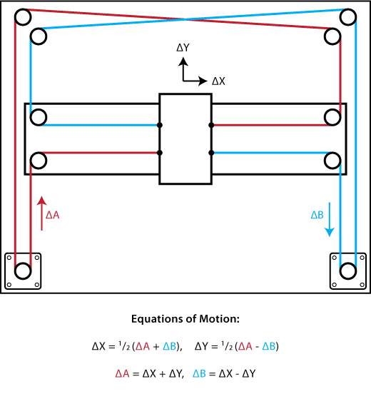
First things first, I have to define the technique for the movement of the axes, since I will use pulleys and belts instead of threaded rods to reduce the weight a bit, I decided to apply the CoreXY technique, below I detail some of the characteristics that seemed more important:
-
CoreXY provides a fundamental building block of many computerized fabrication tools - cartesian motion - in a simple and adaptable format.
-
CoreXY is a technique, not an implementation. We sketch the concept and give a few examples as a platform that enables you to build new tools that are as unique as your ideas.
-
CoreXY’s (mostly) parallel kinematics mean that the motors, typically the largest source of inertia on a DIY-grade stage, are stationary. This permits rapid accelerations.
-
CoreXY can be implemented with only three structural plates, all of which can nest during fabrication.
-
Whether your medium is fabric or aluminum, the principle behind CoreXY permits motion stages to be rendered in a variety of materials and a wide range of sizes.
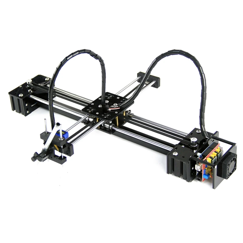
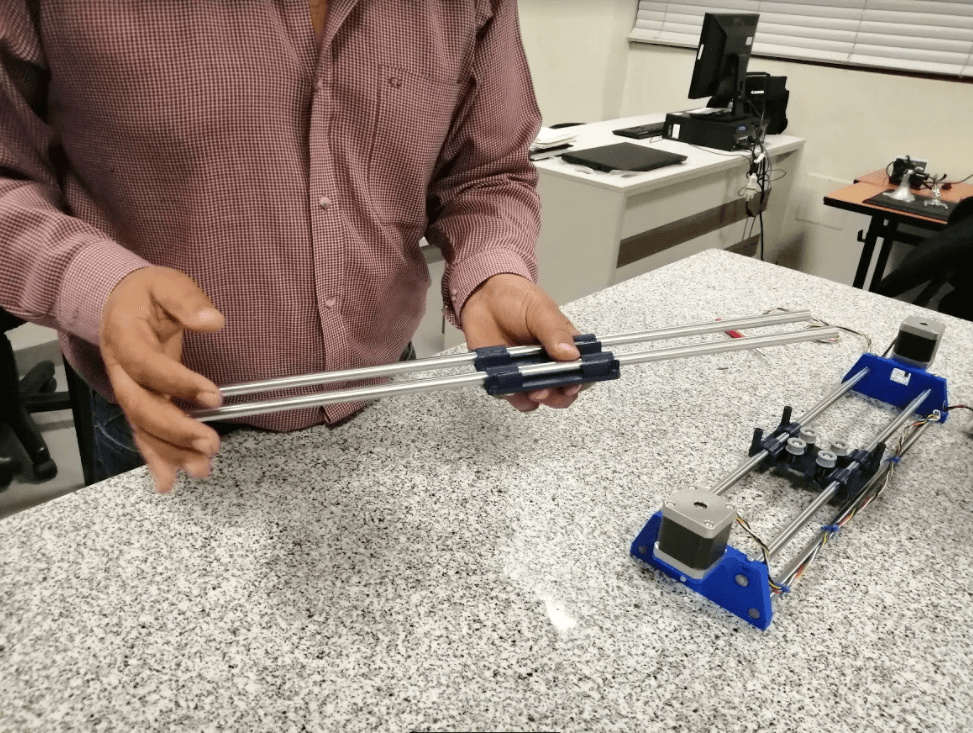
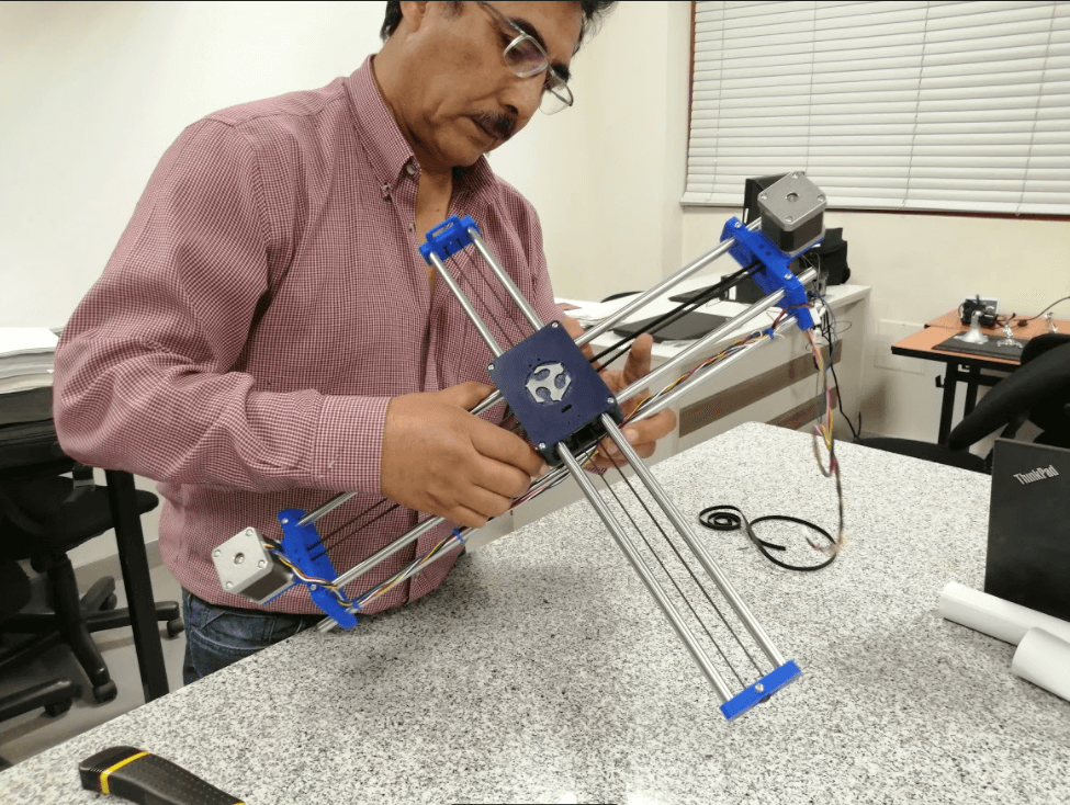
If a drawbot search is done on the internet, many similar results will appear that will serve as a starting point for the elaboration of my machine, first I have to define the amount of 3D printed parts that will be necessary for the frame: 2 pieces for the X axis, 2 pieces for the Y axis, 2 pieces for the middle support and a piece in charge of holding the marker.
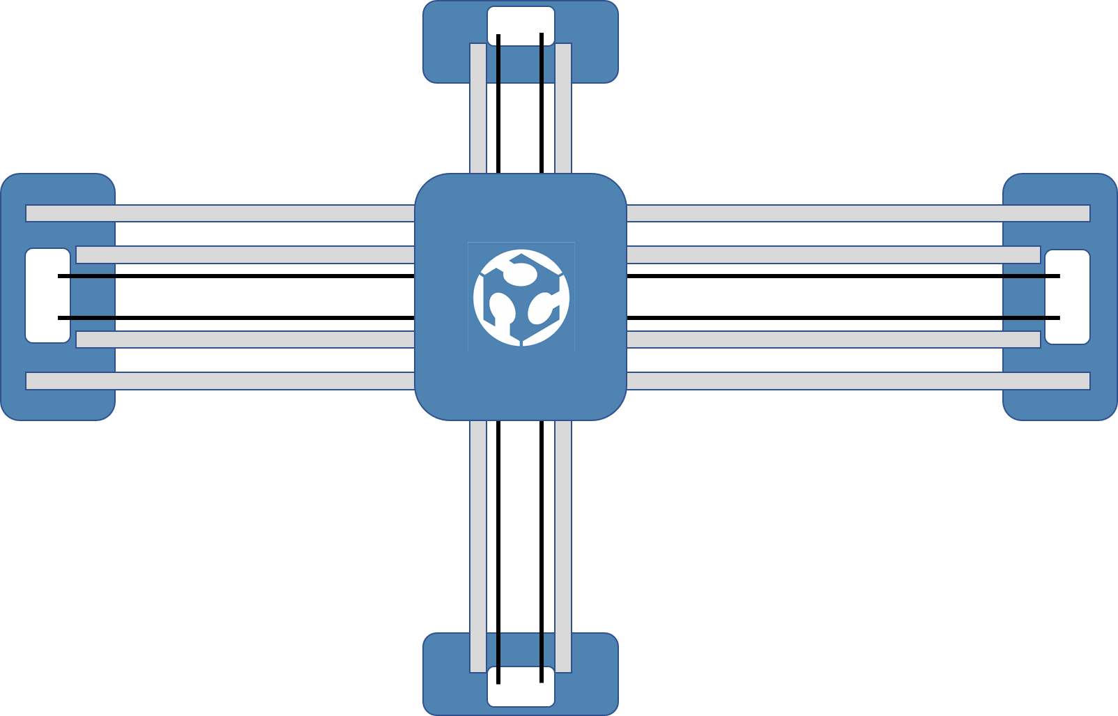
So if I use that image as a reference I can identify that there are 2 pieces that are in charge of holding each axis and a main piece that connects both axes with the belts, regardless of the piece that will be responsible for holding the marker, I must also be careful to respect the distance between the smooth rods throughout the scheme to allow good displacement all over the axes.
The important measurements that I must take into consideration when making the parts are the mounting holes of the Nema 17 motors, the diameter of the smooth rods (10mm) and the thickness of the GT2 belt (6mm).
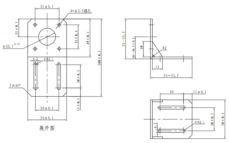
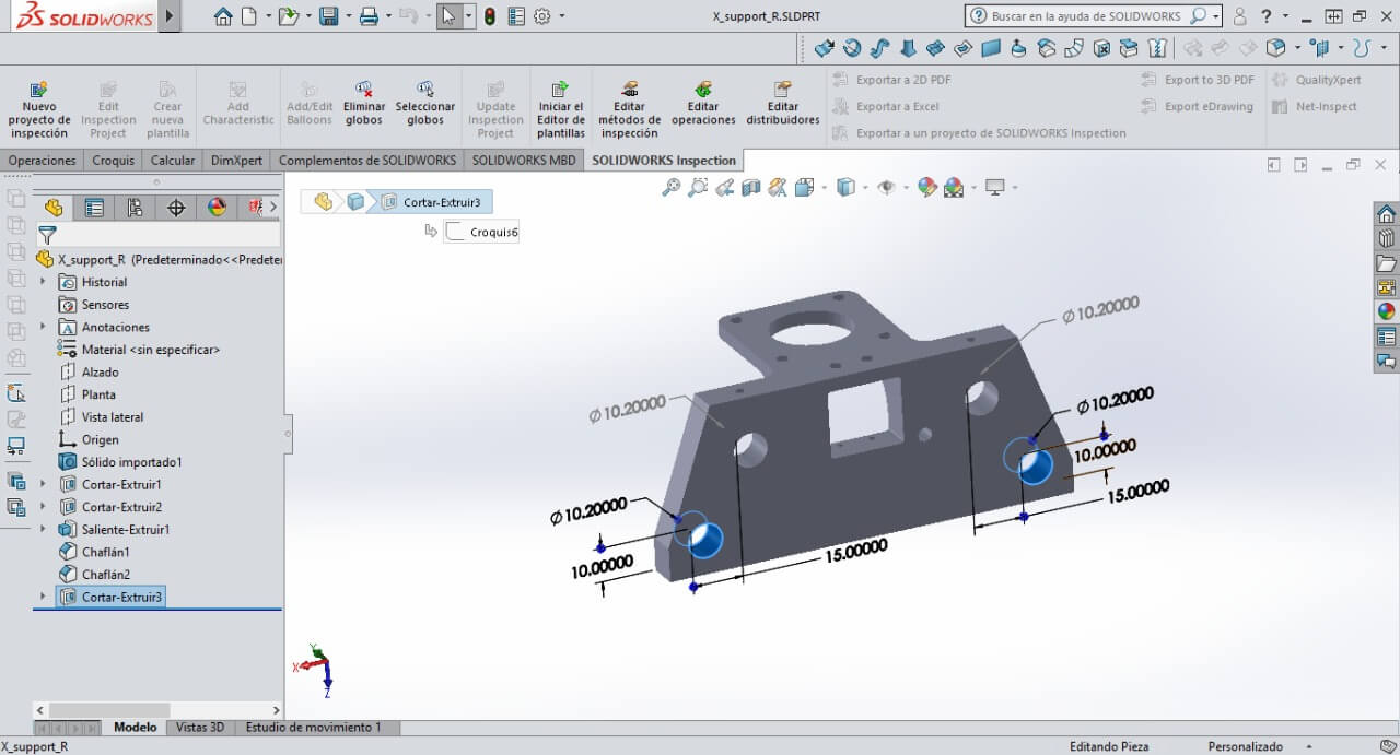
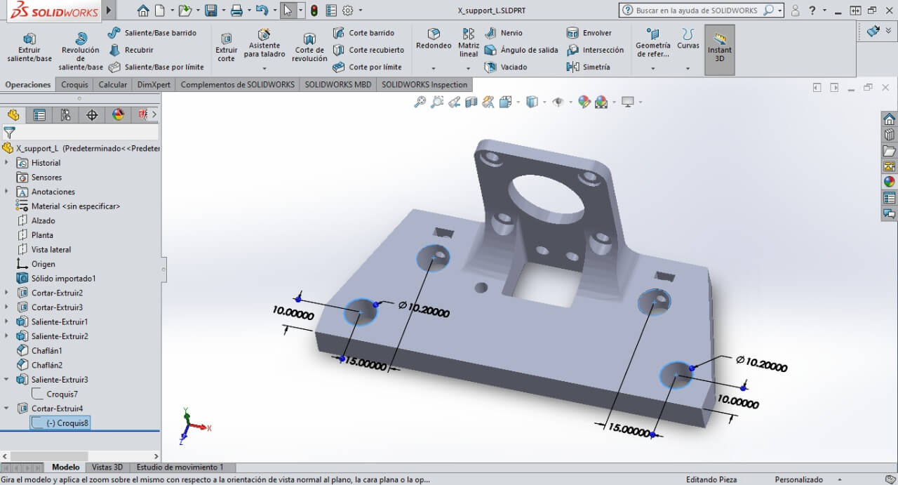
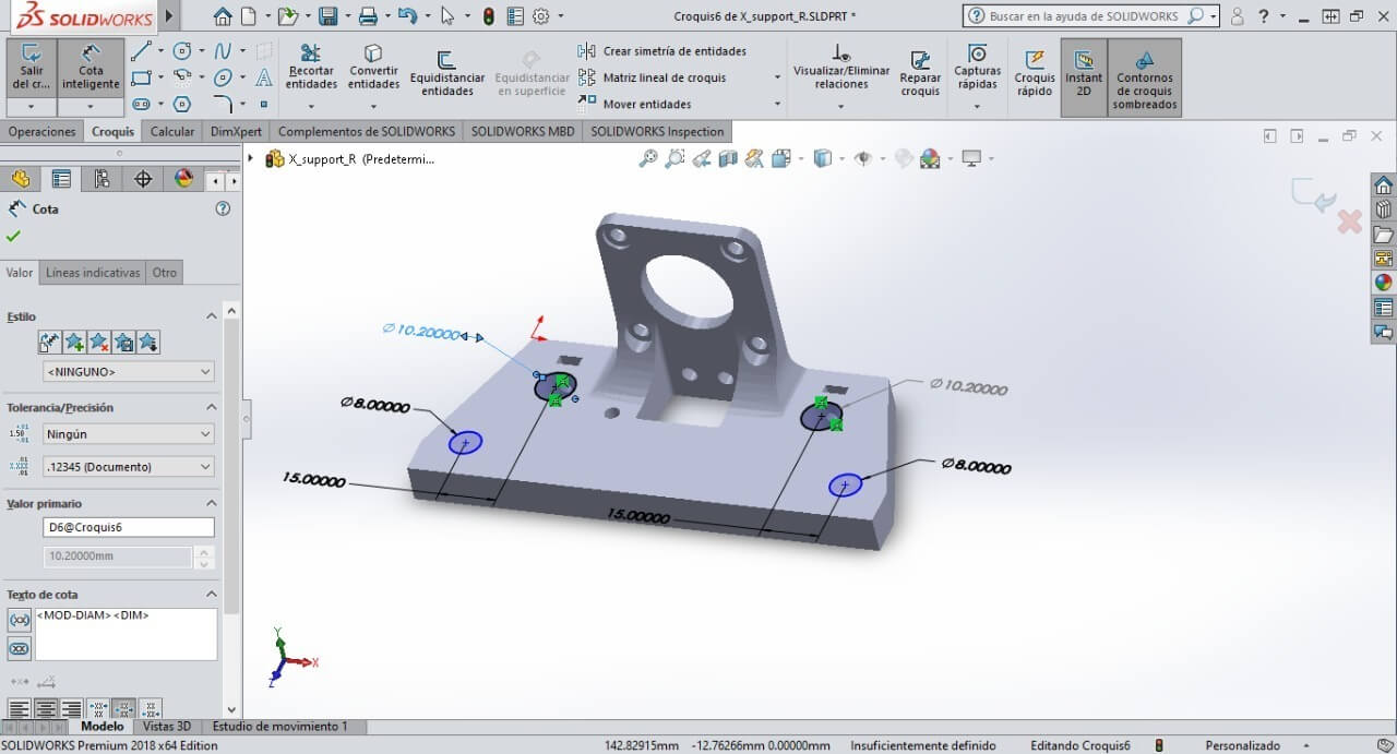
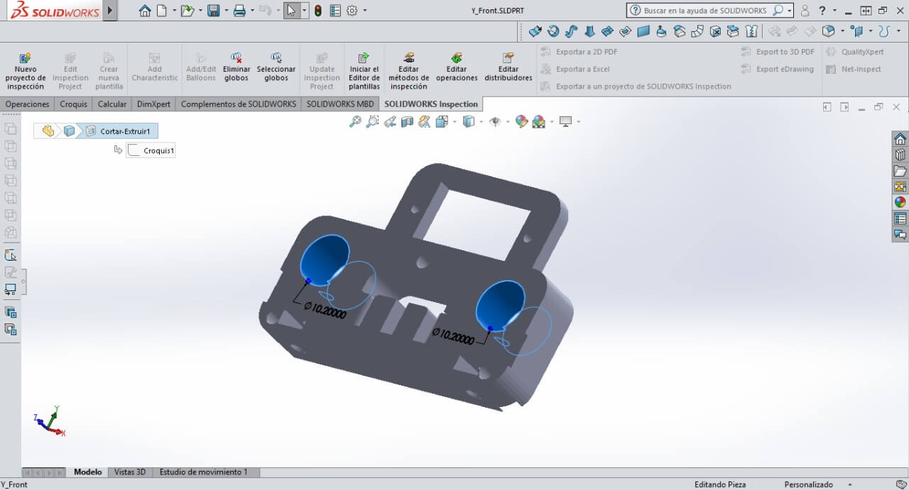
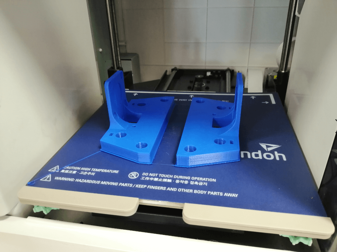
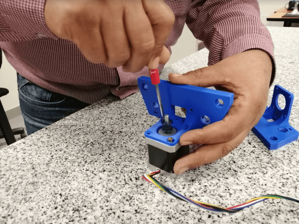
With all of that defined I can start to make the parts in Solidworks, I will start designing the X axis parts, which will be in charge of holding both Nema motors, as shown in the diagram I will use 4 smooth rods to add weight to the axis, I consider it to be something important to prevent the entire chassis from shaking when performing the movements, obviously that can also be solved by reducing the speed and acceleration of the movements, as you can see in the image, I don’t directly enter the value of 10mm for the holes in the shafts, since my printer’s tested resolution showed it to have 0.2mm offset, so I will assign 10.2mm for all rod holes.
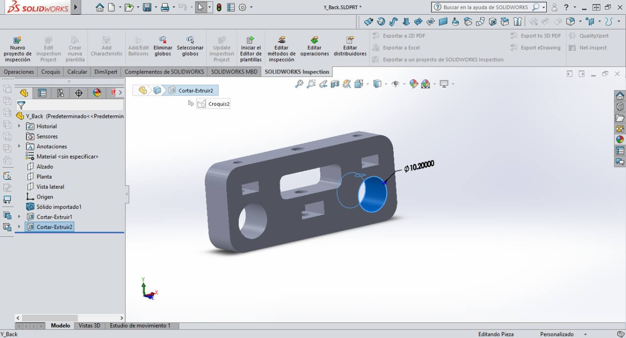
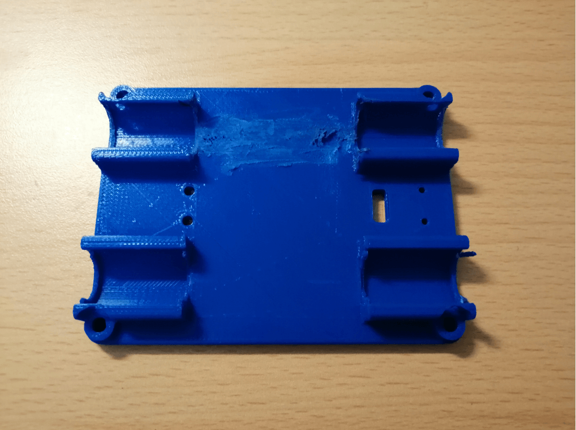
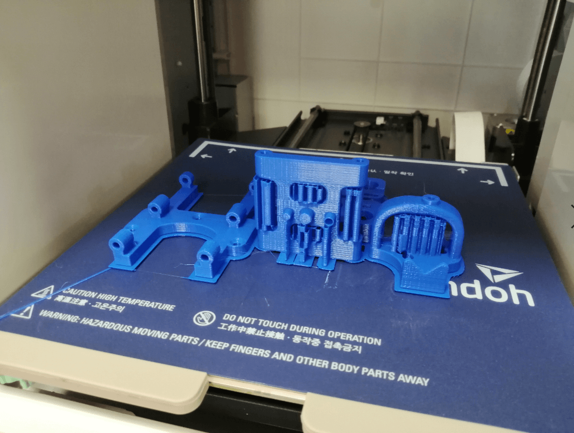
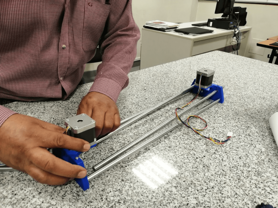
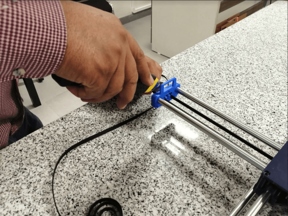
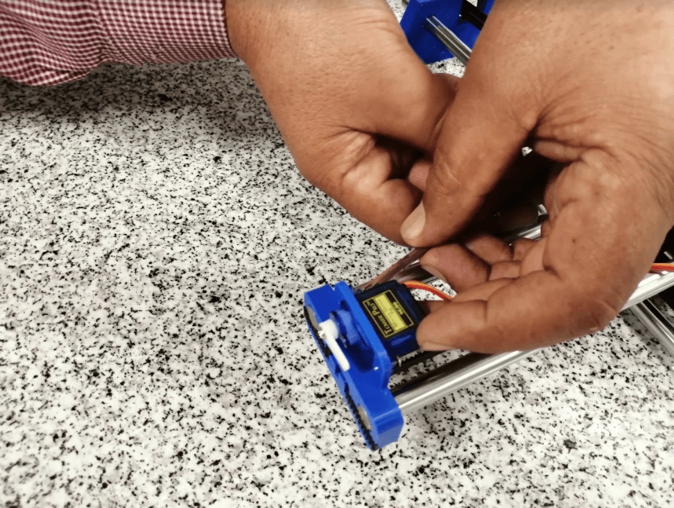
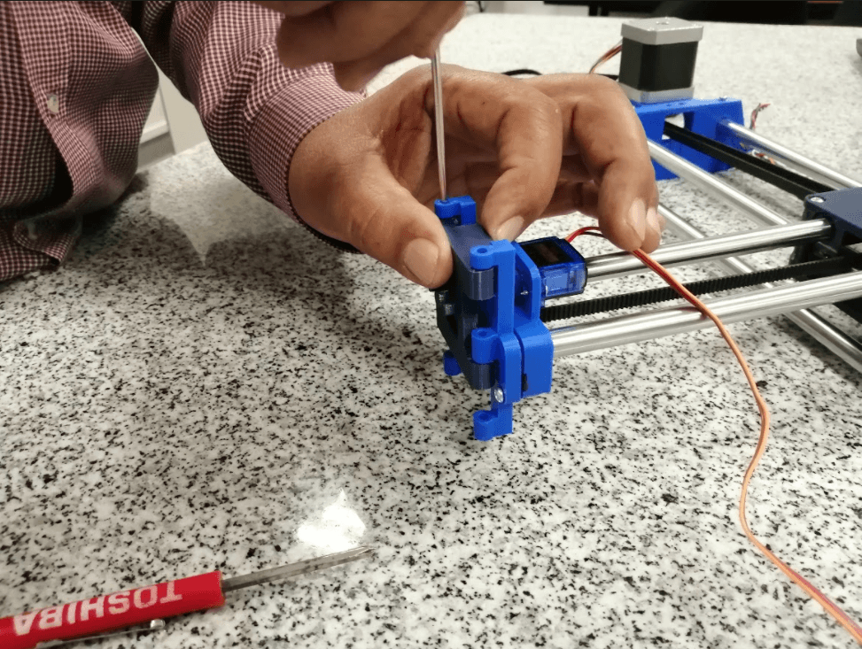
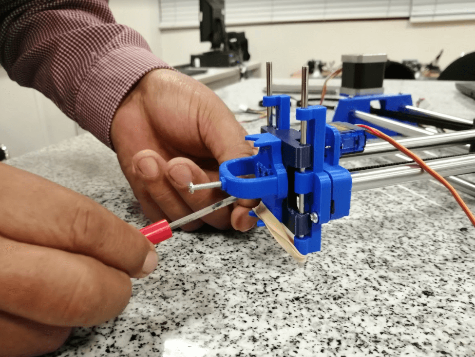
Continuing with the design, now it is the turn of the Y axis, I consider that this is simpler because it doesn’t have to hold motors, only rods and belts, also a piece will hold the servomotor in charge of pressing the marker on the surface in which we are going to draw, it is important to add a captive screw in the holes of the bars to hold them and prevent them from slipping otherwise we will have to reinforce that piece with glue.
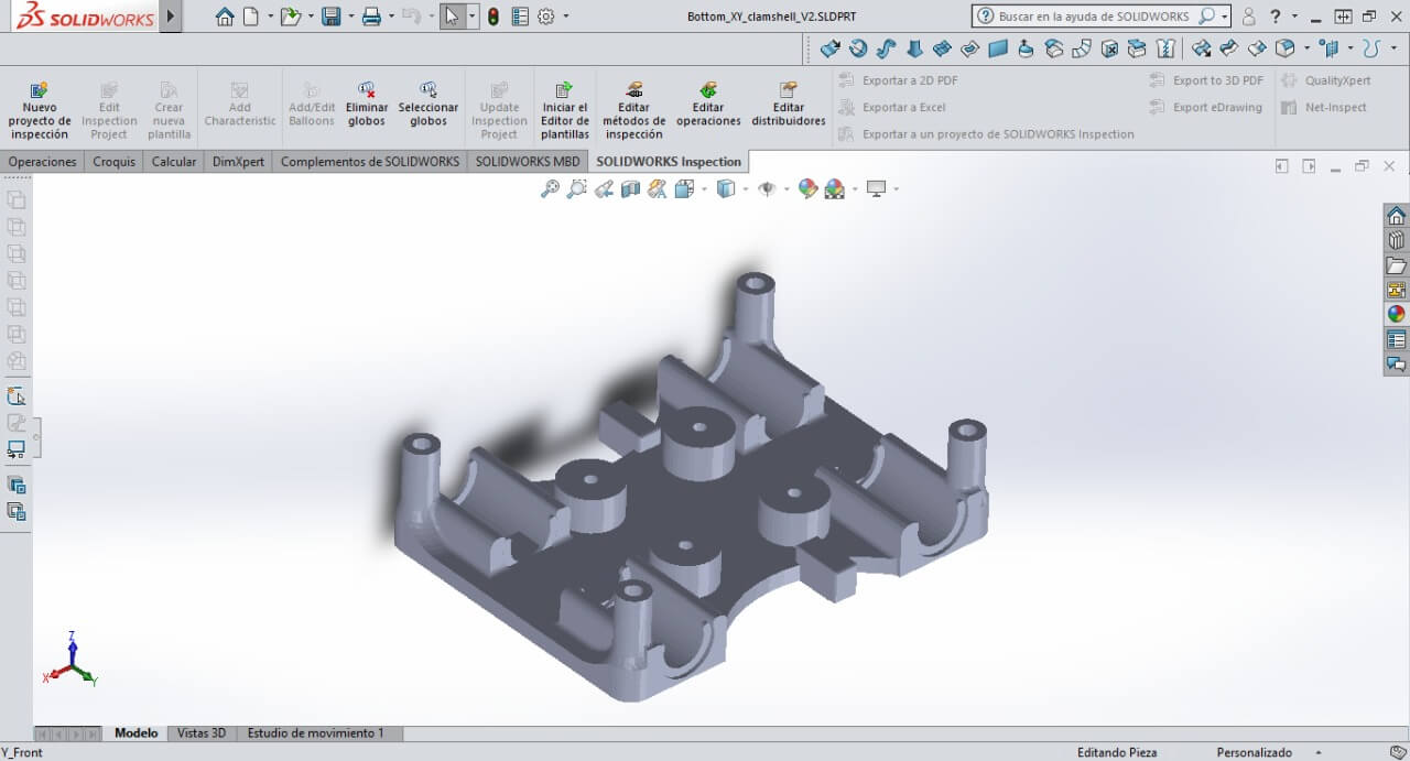
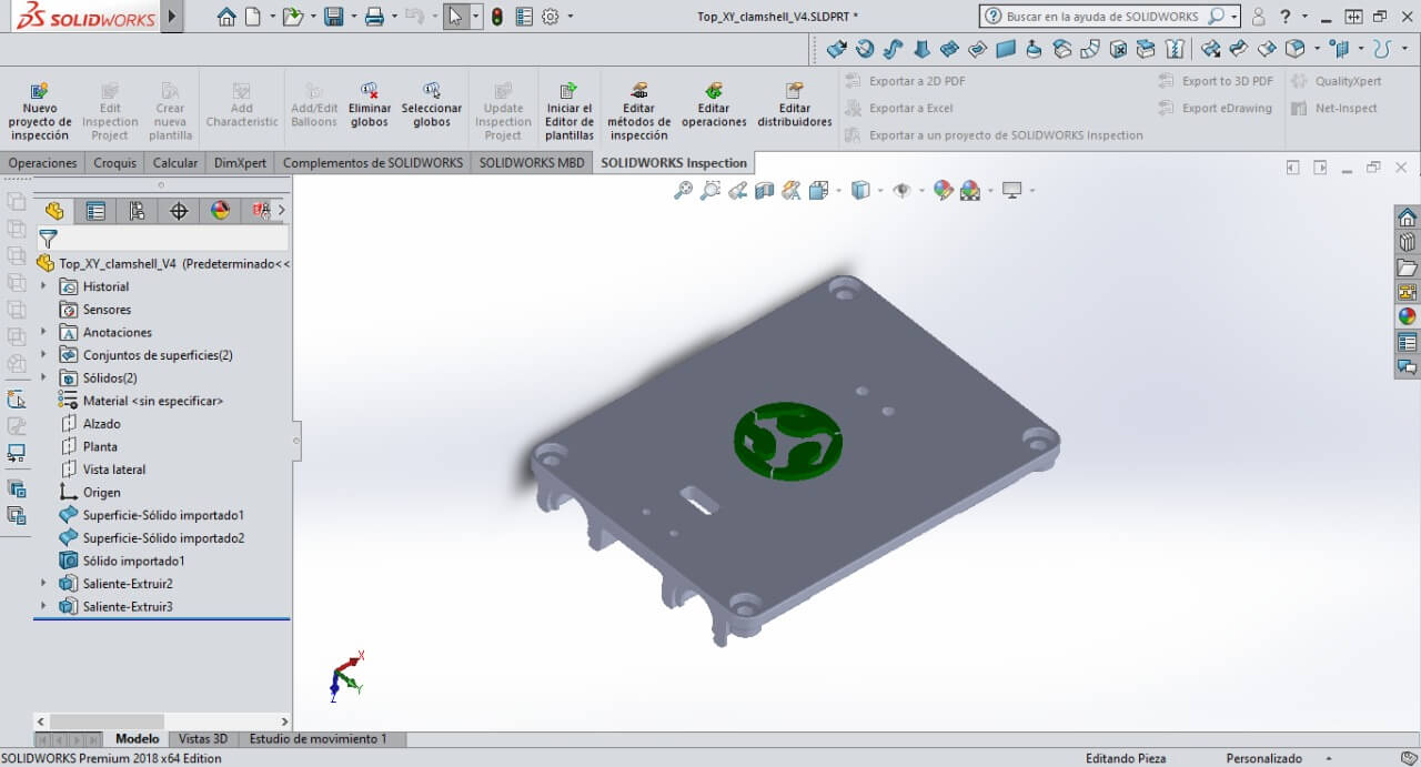
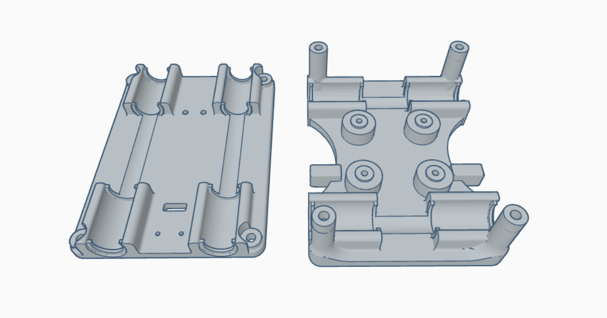
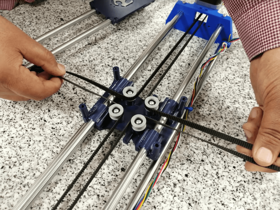
Finally, the middle piece that will connect both axes will be elaborated, it has 4 bearings to guide the belts and 4 linear bearings to guide the rods to avoid friction, I decided to add the fablab logo to give it a personalized touch and that was all to do (That was what I thought, but I was wrong).
Fitting problems
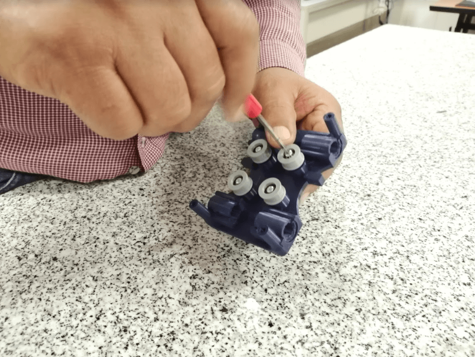
The first problem showed up because I couldn’t get the linear bearings for the rods, so I decided to print them in 3D, since it was the most correct option due to the little time I had left, unfortunately due to the offset of my printer the part did not fit the first time it was printed and it was all a process of trial and error.
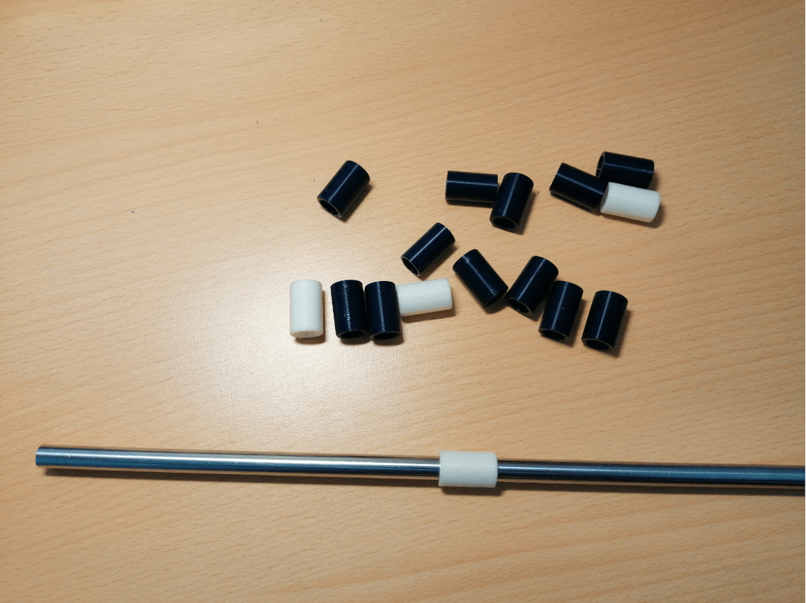
When i thought that the inner diameter of the linear bearing was correct, I realized that now the problem was the outer diameter because when it was fitted with the middle piece it tended to bend a little, as if it were not enough, the rod collided with the part and could not move properly, in a desperate attempt to solve the problem I decided to sand the surface with a dremel, but everything resulted in melted plastic and a useless part.
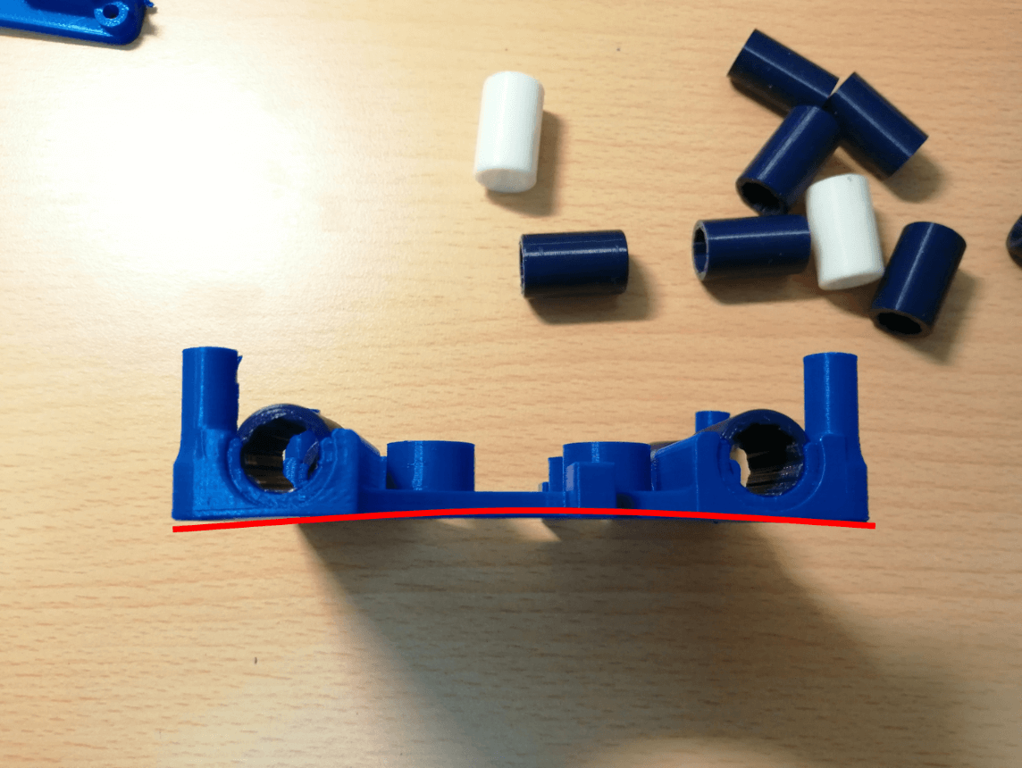
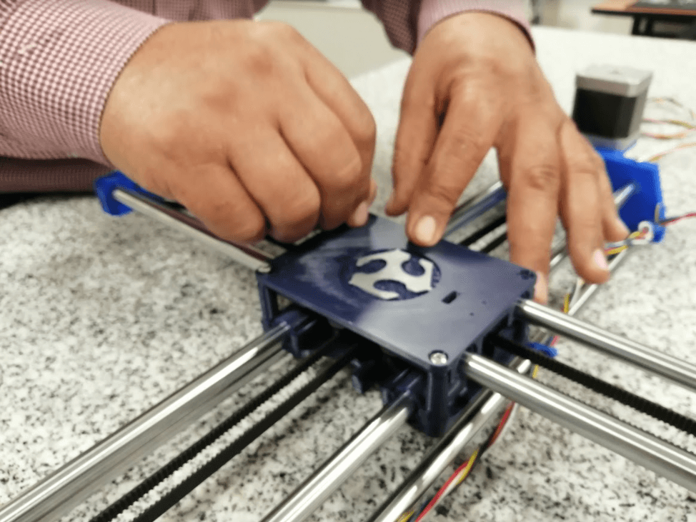
I understood then that to avoid more problems these pieces should be printed again, but with extra modifications that I found at the time of assembly (such as raising the bearings a little to avoid the use of spacers), luckily the second version worked well and no further changes were necessary.
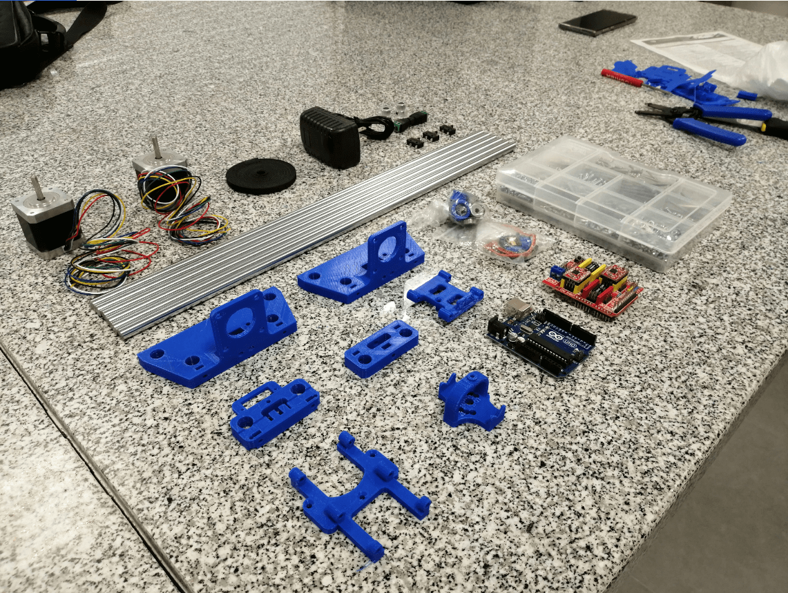
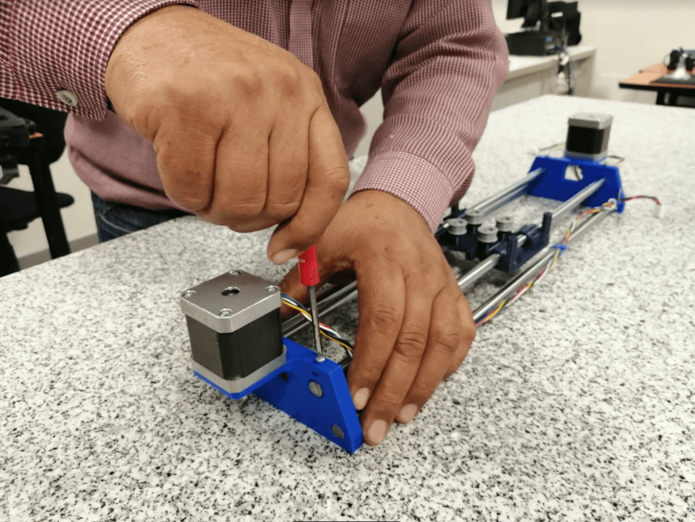
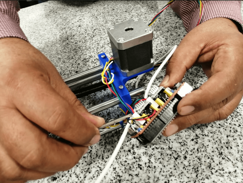
Construction
Operation
To control the CNC I will use GRBL, Grbl is a no-compromise, high performance, low cost alternative to parallel-port-based motion control for CNC milling. It will run on a vanilla Arduino (Duemillanove/Uno) as long as it sports an Atmega 328.
The controller is written in highly optimized C utilizing every clever feature of the AVR-chips to achieve precise timing and asynchronous operation. It is able to maintain up to 30kHz of stable, jitter free control pulses.
It accepts standards-compliant g-code and has been tested with the output of several CAM tools with no problems. Arcs, circles and helical motion are fully supported, as well as, all other primary g-code commands. Macro functions, variables, and most canned cycles are not supported, but we think GUIs can do a much better job at translating them into straight g-code anyhow.
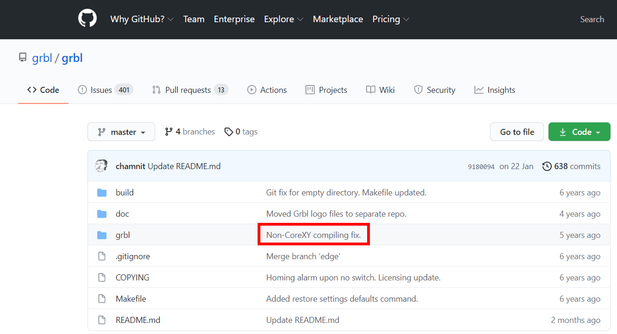
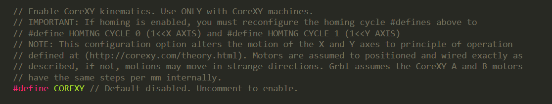
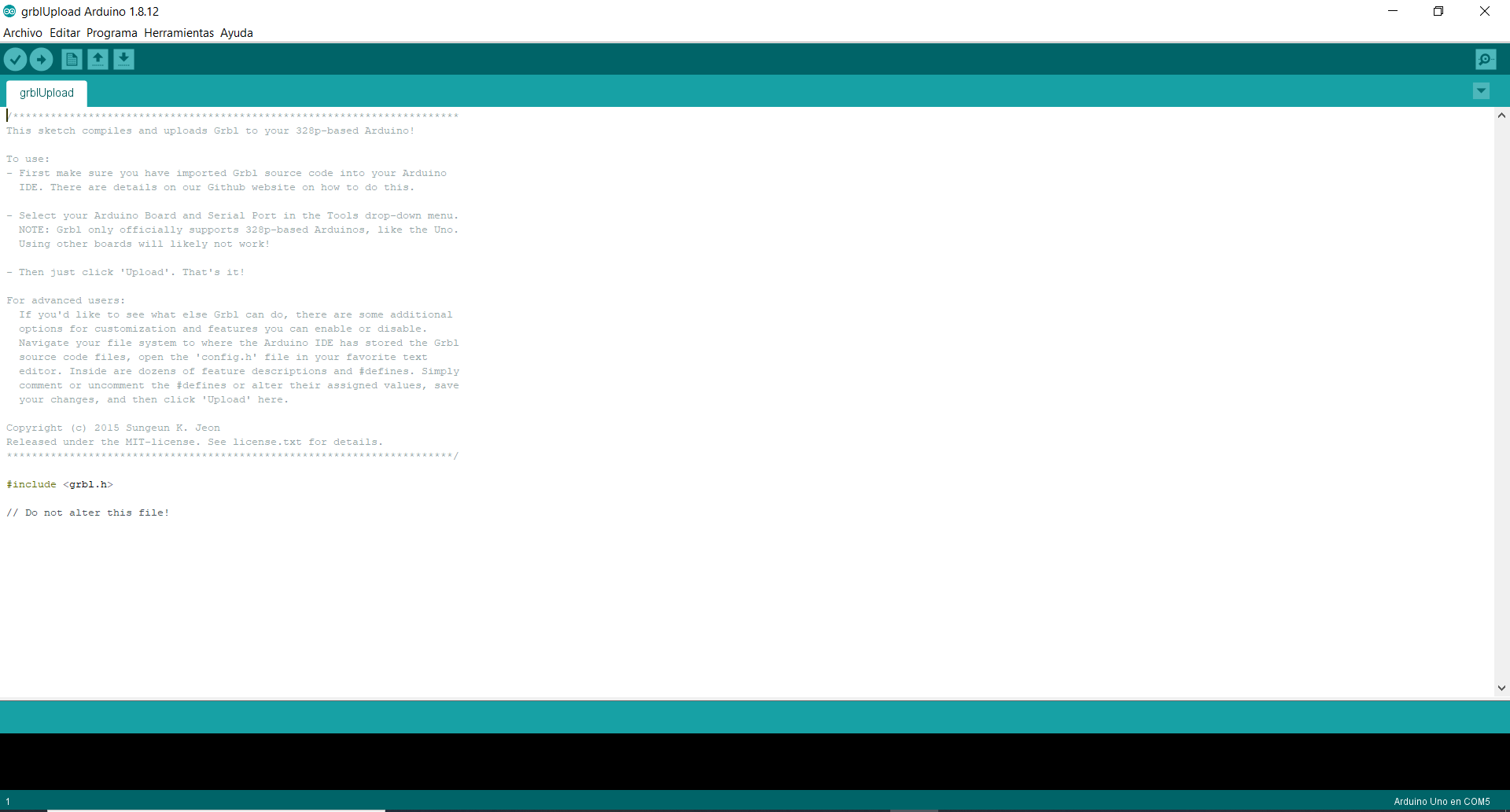
First we must download the grbl - master.zip folder from the GRBL repository, it is super important to check the part marked in red, it indicates that the config.h file is settled to work with a machine that is not CoreXY, so what we must do is modify it, the best way to perform this procedure is to first install that library by default in the Arduino IDE and then look for the path where the library was installed and open the file with a text editor, in this case I use Sublime Text 3 and look for the line of code referencing CoreXY and I disabled it as a comment, you need to comment on the settings above.
We search in File -> Examples -> GRBL -> grblUpload, we open and compile it to check that there is no problem with the modification we make, then we can upload the file to our Arduino UNO, it is important that to upload the file we remove the CNC shield from the Arduino to avoid communication problems, once all this is done, it would be ready to receive the commands to move the axes.
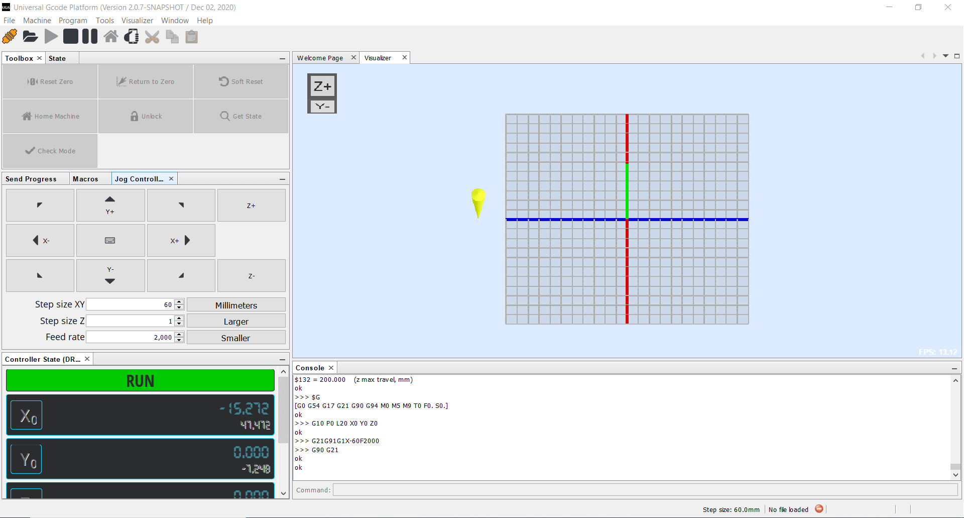
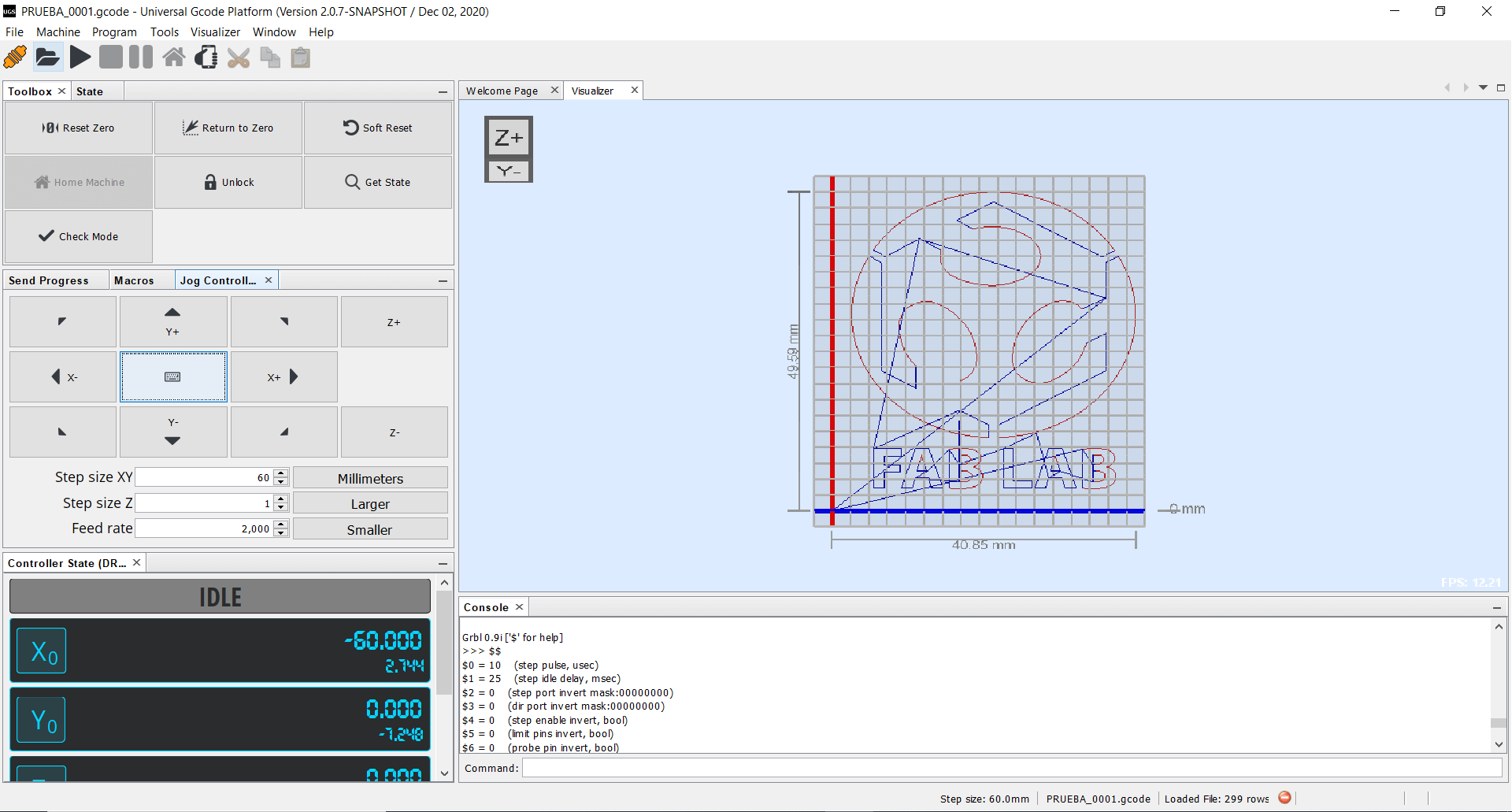
Now we need to download Universal G-code sender, it will be the interface that will allow us to control our CNC plotter through commands or by entering g-code files. The first step is to link our Arduino with the UGS interface, we have to connect the Arduino to the USB port through the cable, then we open UGS and a button called Connect will appear in the upper left corner, before clicking we must check the following information:
- Firmware: GRBL
- Port: COM port assigned to Arduino
- Baud: 115200
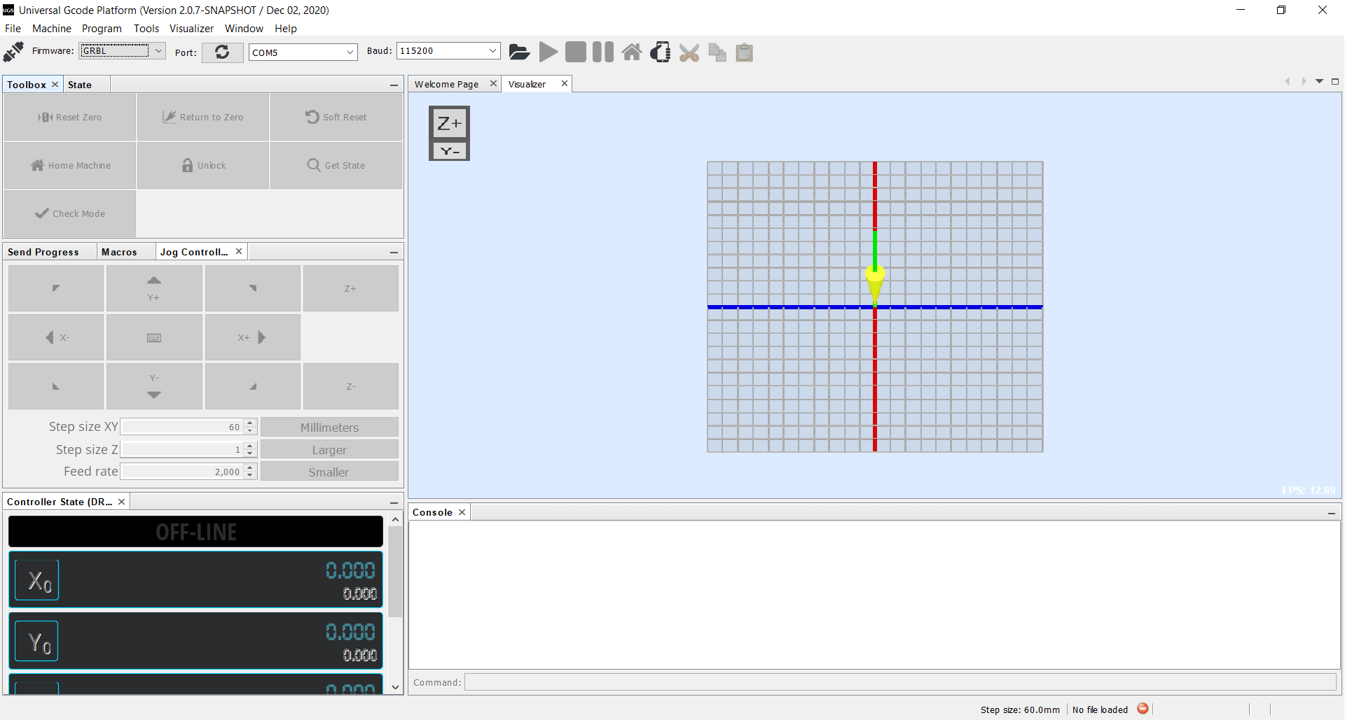
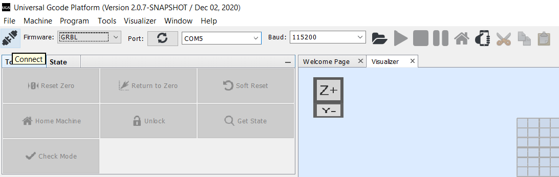
Once connected, the symbol will turn orange and values will appear in the console window, that will confirm that we managed to connect correctly, as you can also see, all the buttons now allow to be pressed except for the Home button, this is because we are not using end stops for the axes.
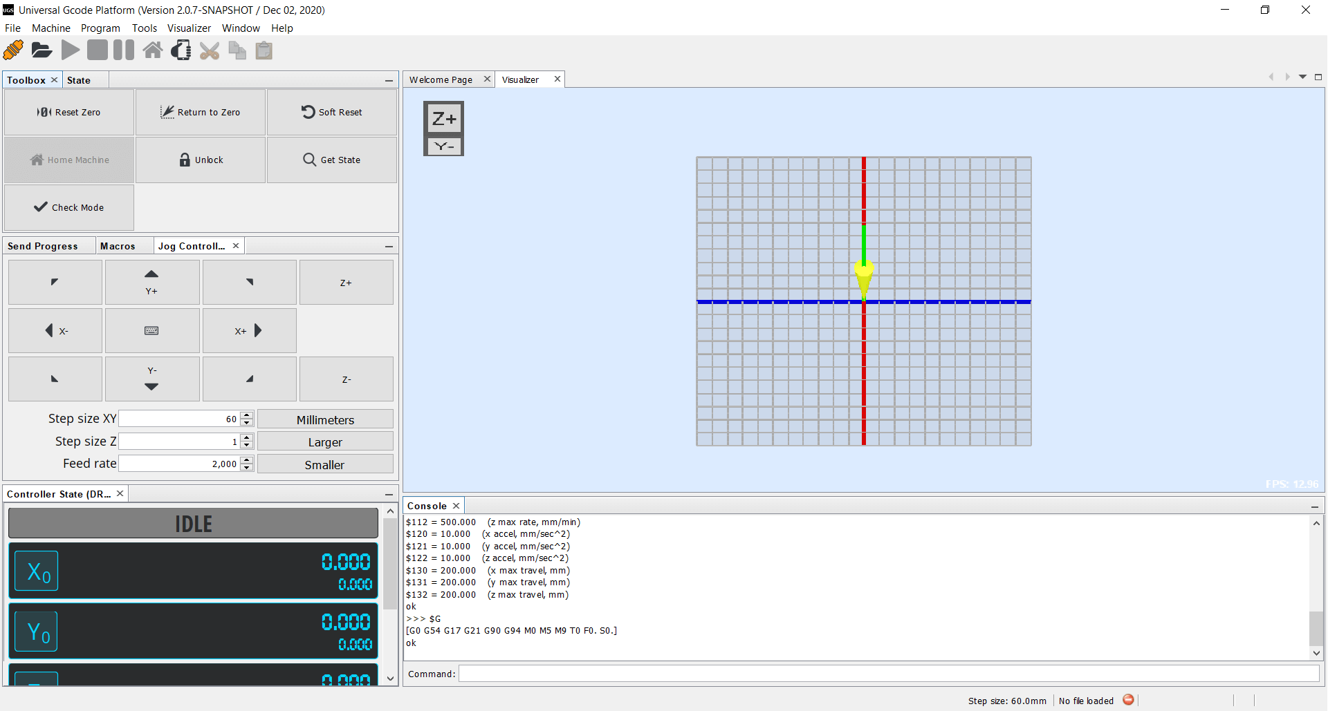
Now we can check that our motors are working correctly using the Jog Controller, the most important thing is to check that the axes move straight and only one axis moves when pressed, otherwise we must check the connection of the motor cables or maybe the GRBL configuration that we upload to our Arduino, fortunately our machine worked correctly and we were able to check parameters such as step distance, speed and acceleration.
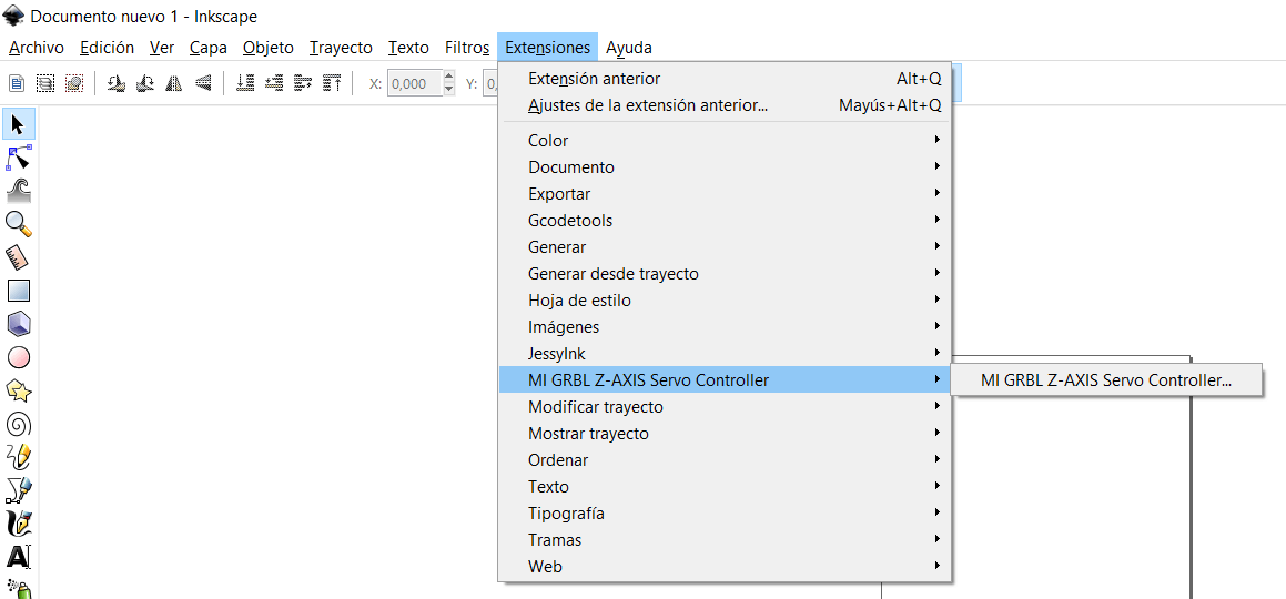
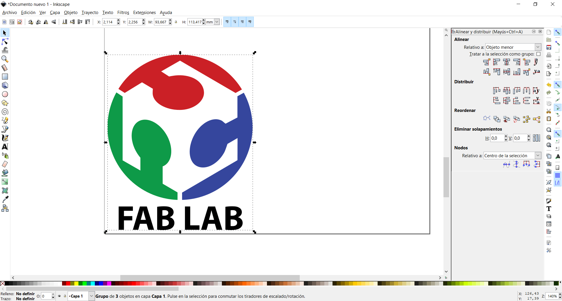
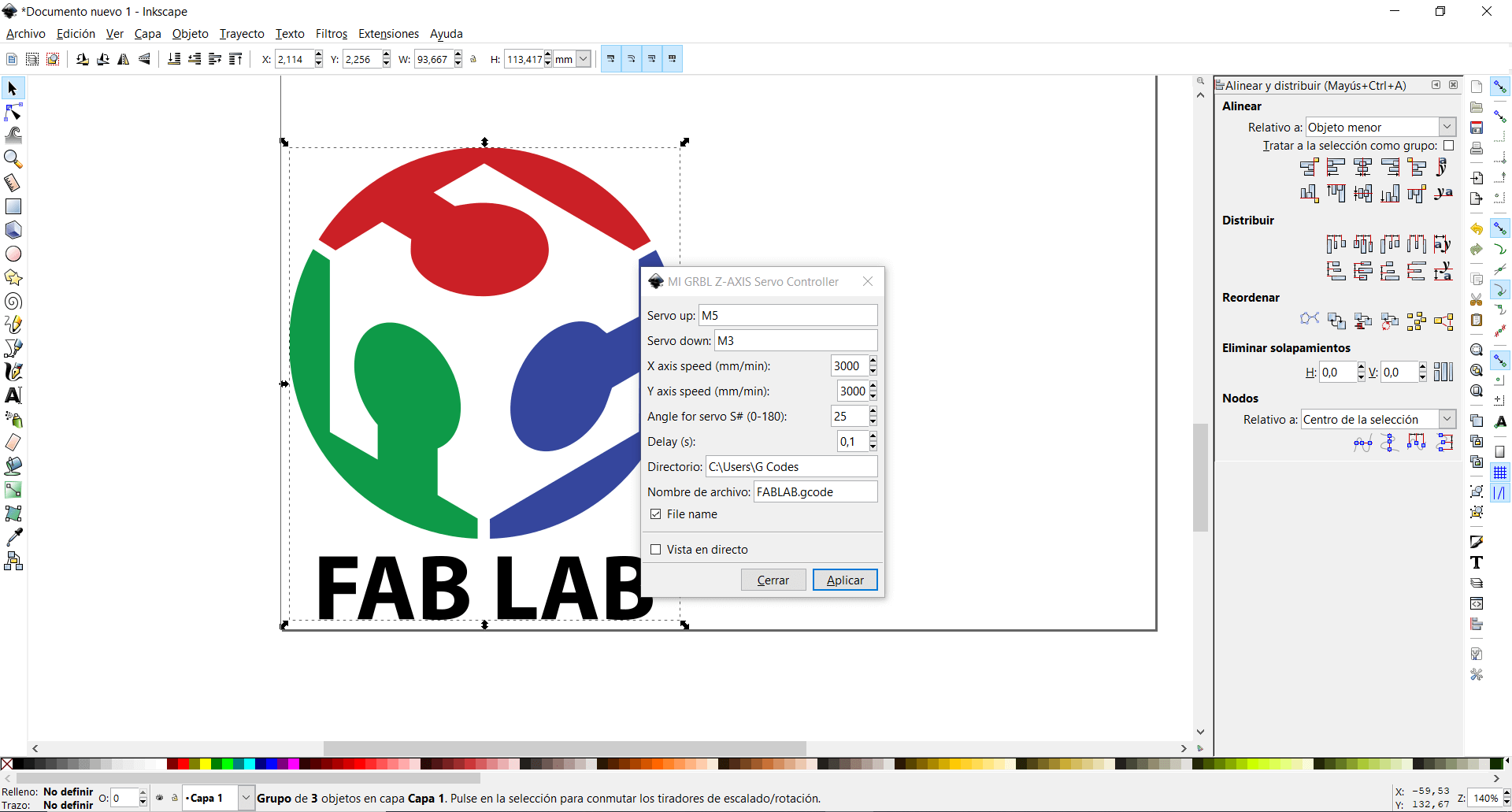
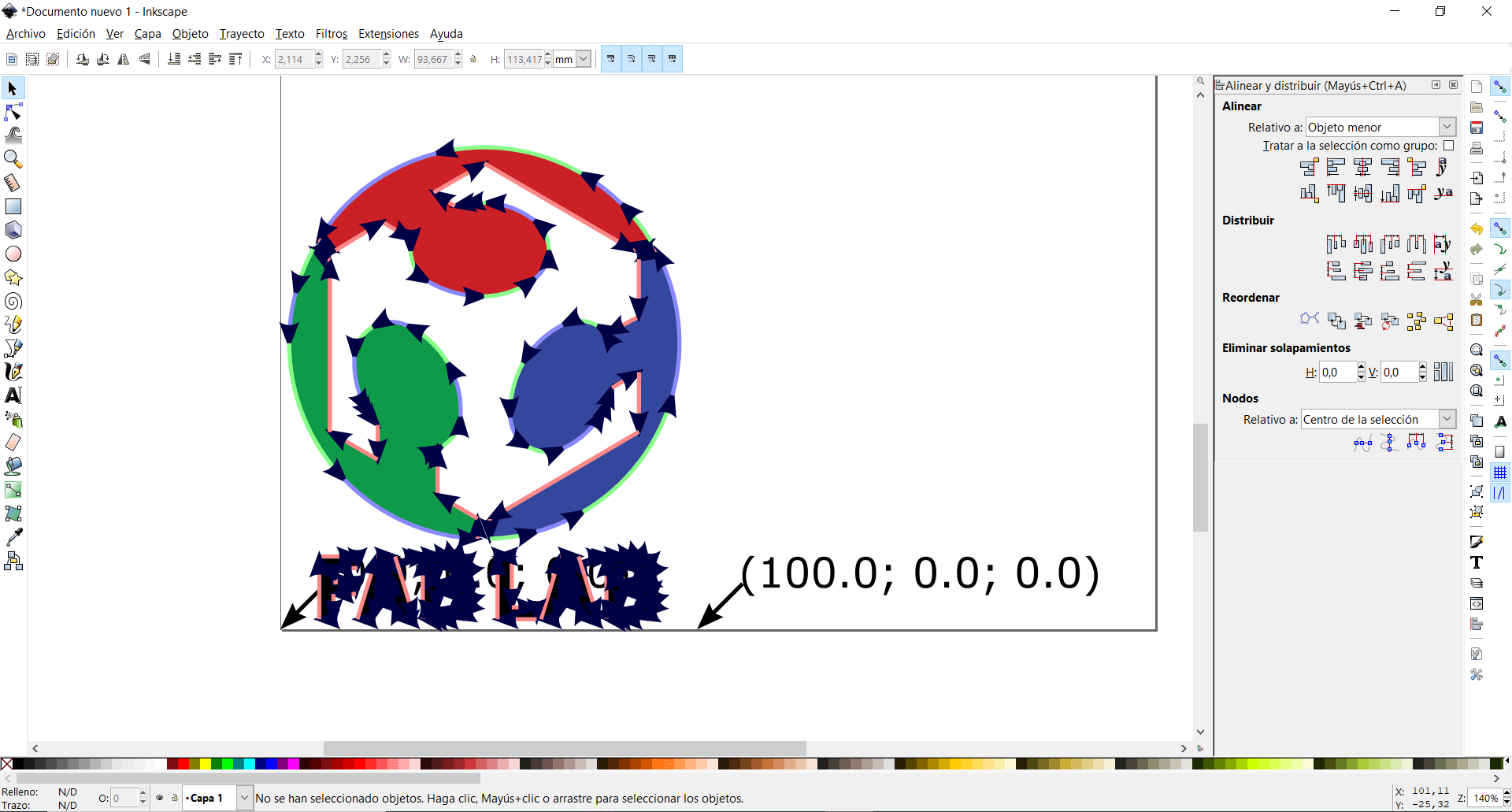
We can generate our own g-code files, for that I will use an Inkscape extension that allows me to transform images into trajectories, the name of the extension is MI GRBL Axis Servo Controller and it is not complicated to add or use, also it is very similar to this extension Inkscape Laser plugin recommended for CNC plotting, but I wasn’t able to fully understand how it works, but their tutorials were very useful to allow me to generate the files.
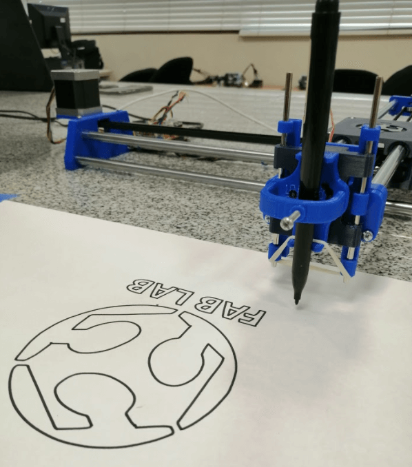
After doing some tests I found the right speed and angle so that the servomotor could lift the marker, I also had a problem with the UP and DOWN commands, since I had them set inverted, this caused the marker to rise at the moment of drawing and going down when advancing, but it was easily solved with the M3 and M5 commands.
Assembly and operation video
Files
- bottom.stl
- top.stl
- X support L.stl
- X support R.stl
- Y Back.stl
- Y Front.stl
- Slider.stl
- Sslider base.stl
- Pen holder.stl
- LM10 linear bearing.stl
- GT2 16T toothed pulley.stl
- Pulley.stl
Week Assessment
During this week, have I :
-
[ ] Documented the machine building process to the group page ? There were several attempts, but they helped me to fully understand the operation of the machine.
-
[ ] Documented my individual contribution to the project on my own website ? My individual contribution includes all the work that a group should do, since I did it myself.
-
[ ] Shown how my team planned and executed the project (Group page) ? As I mentioned before, I was in charge of the entire project.
-
[ ] Described problems and how the team solved them (Group page) ? There were problems in the assembly and some in the programming, if it wasn’t for the 2 weeks deadline I am sure that I wouldn’t have been able to finish the project
-
[ ] Listed future development opportunities for this project (Group page) ? I believe that this platform can have an infinity of uses, limited only by the creativity of the user, with more time and dedication I would liked to transform it into a cake decorator or perhaps a pancake machine.
-
[ ] Included my design files (Group page) ? CAD files were too heavy, I shared all the .stl files so if you follow correctly my instructions you will have an identical plotter.
-
[ ] Optionally included an aprox. 1 min video (1920x1080 HTML5 MP4) + slide (1920x1080 PNG) (Group page) ? You can check the Assembly and operation video section.