6. 3D Scanning and printing
This week’s assignment introduces us to the world of 3D printing and also scanning, the 3D printing field is already highly developed and I had the opportunity to do different jobs in 3D printing, but I never thought about the design rules to make a prototype correctly, that is why some pieces that I printed ended up using many supports or they didn’t fit correctly, I hope this assignment helps me to understand more the capabilities of our Sindoh 3DWOX1 printer.
On the other hand, I always related 3D scanning with very expensive machines, Neil spoke about Meshroom, a tool that transforms a set of photos into a 3D object, so learning how to use it correctly will be my goal for this assignment.
Assignment
group assignment:
- test the design rules for our 3D printer(s).
individual assignment:
- design and 3D print an object (small, few cm3, limited by printer time) that could not be made subtractively
- 3D scan an object (and optionally print it)
Group assignment
In order to carry out the individual assignment correctly, we must understand the operation of our 3D printer, for that we will identify different parameters such as:
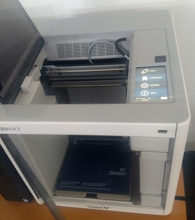
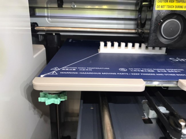
Due 3D printing is a slow process, we decided to choose 3 parameters to run the tests, I consider that the important parameters are clearance, angle and bridging, since they will determine the characteristics of the piece that I plan to elaborate later. In our laboratory we have the Sindoh 3DWOX 1X printer.
Since .stl models are available on the 3D scanning and printing site, getting the part ready for printing is not complicated at all:
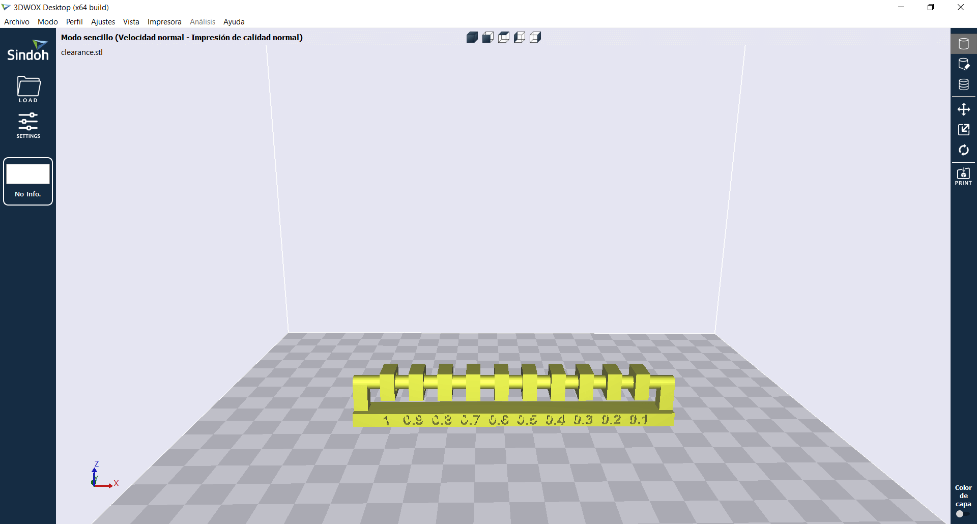
- By default the software already has PROFILES settled by the manufacturer. Anyway we can make changes to these parameters by clicking on the tabs at the top.
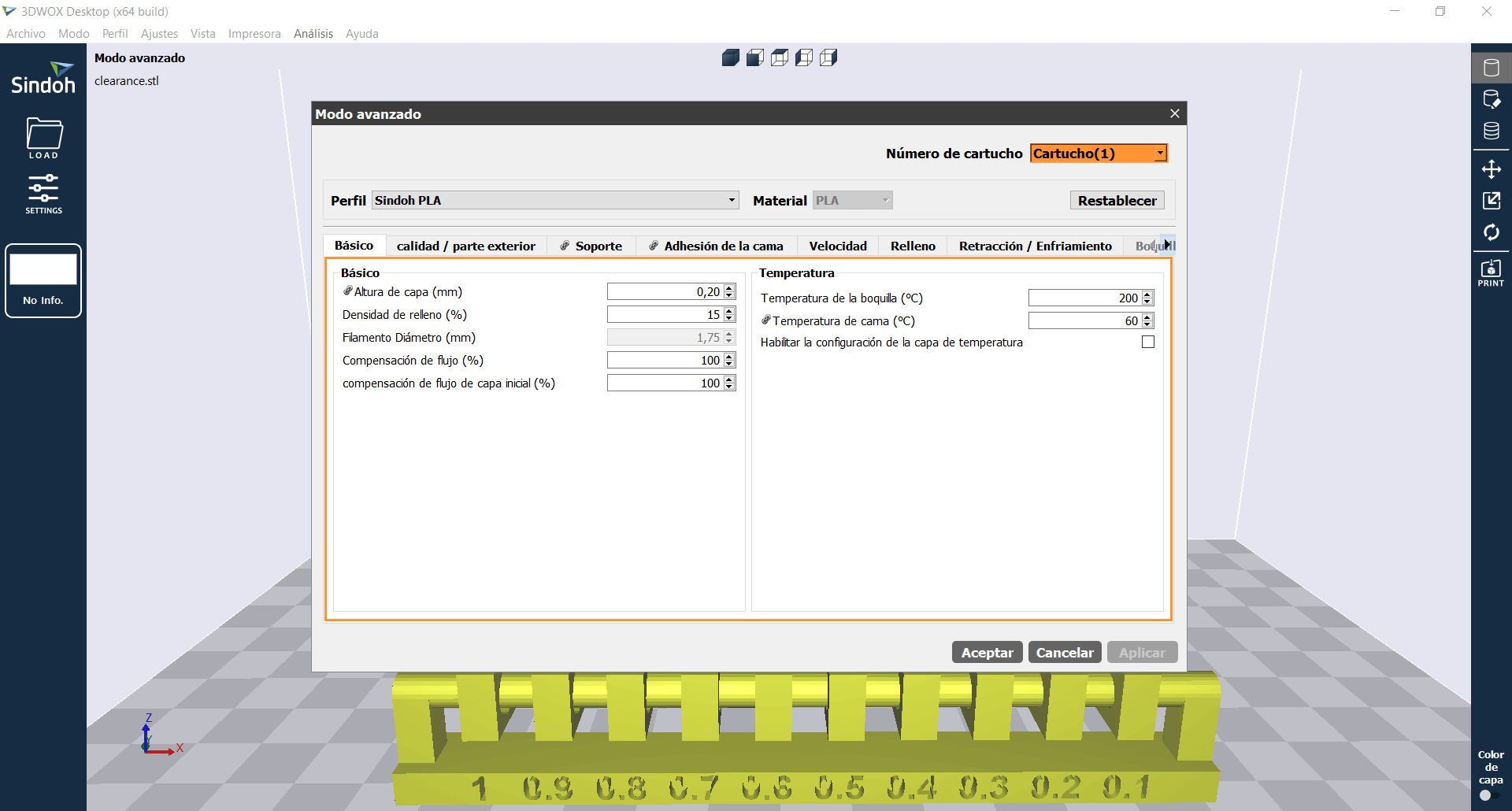
-
All the tests that we are going to carry out will be with PLA and with a layer height of 0.2.
-
We press on the PRINT button and the object is ready to be printed.
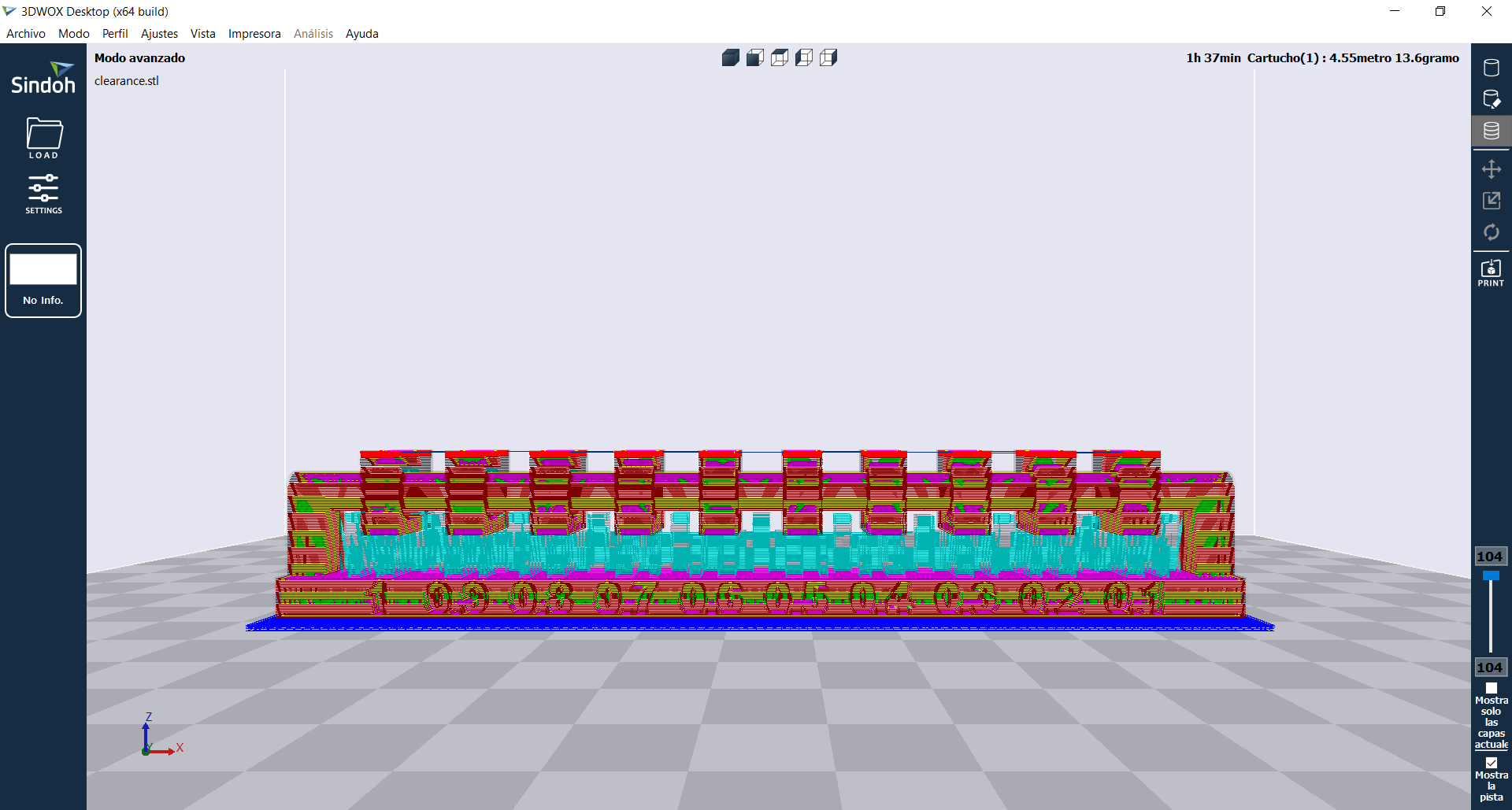
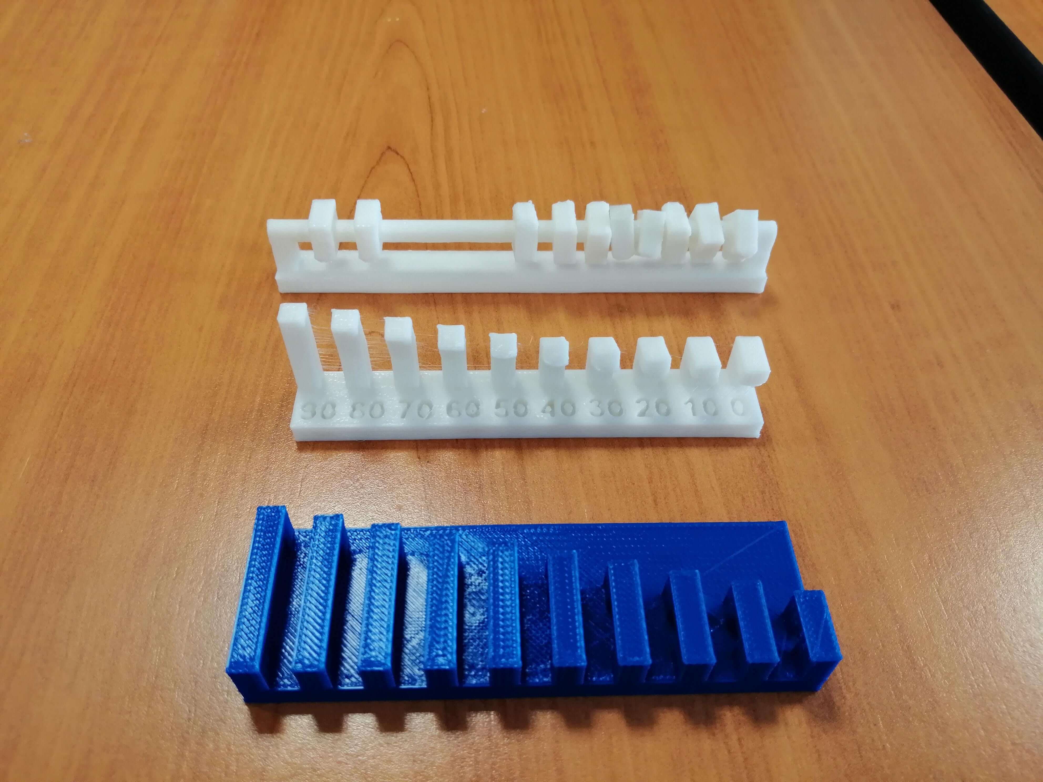
The same process was carried out for the 3 pieces, without modifying any special parameters, the following image shows the final results, now we are going to analyze in depth each of the pieces to identify the capabilities of our 3D printer.
Clearance supported
The purpose of this test is to allow us to determine the minimum resolution that the printer gives us avoiding the piece sticks to the shaft, the diameters increments by 0.1mm and to print this piece it is necessary to use supports.
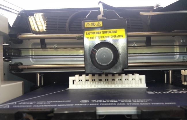
As can be seen in the images, 8 of the 10 pieces were printed without problems, that means that the minimum offset that we can establish between 2 pieces is 0.3mm, the 0.1mm and 0.2mm pieces are attached to the shaft without the possibility of being separated.
Angle unsupported
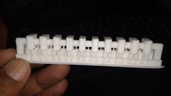
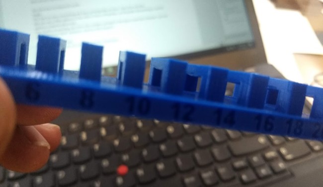
The purpose of this test is to allow us to determine the maximum printing angle without using supports, our printer generates supports by default from 60 degrees according to the pre-established settings, we will check if this value is correct or if we must increase or decrease that value, this test increases the value by 10 degrees from 0 to 90 degrees.
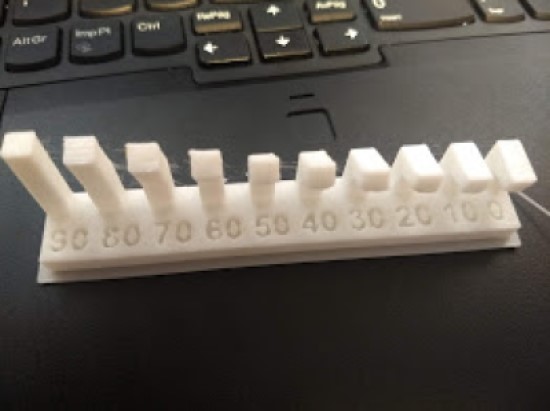
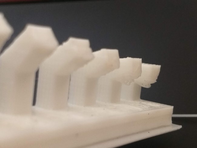
Something important about this test is that we must subtract 100 from the values shown in the part to determine the value that we must enter in our printer, as expected, values close to 0 show overhang until reaching 70 or 60 degrees, another important thing is that the printing speed also influences this test because it allows the material to solidify correctly and perhaps achieve higher angles, for now we will leave the value at 60 degrees, but perhaps it can be taken up to 65 degrees without the need of supports.
Bridging unsupported
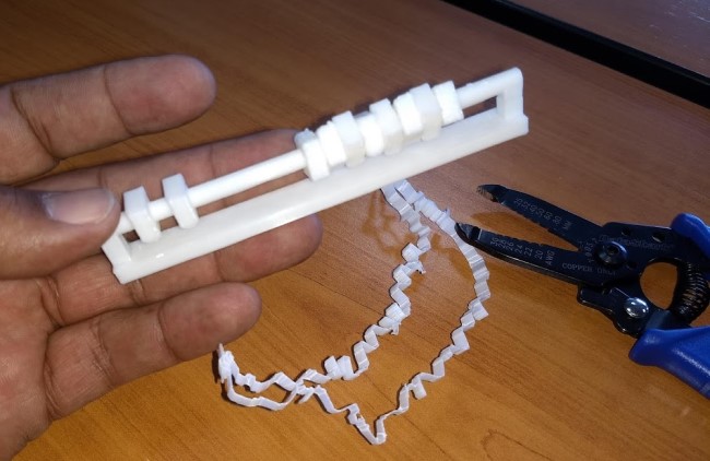
The purpose of this test is to allow us to determine the maximum distance between 2 points without using supports, I consider that this parameter depends a lot on 2 important parameters that are printing speed and flow rate, I remember seeing some challenges in 3D printing groups to see who achieved the longest bridging distance, the test for now will be done without modifying the printer parameters, just to know the standard distance our printer can reach.
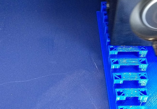
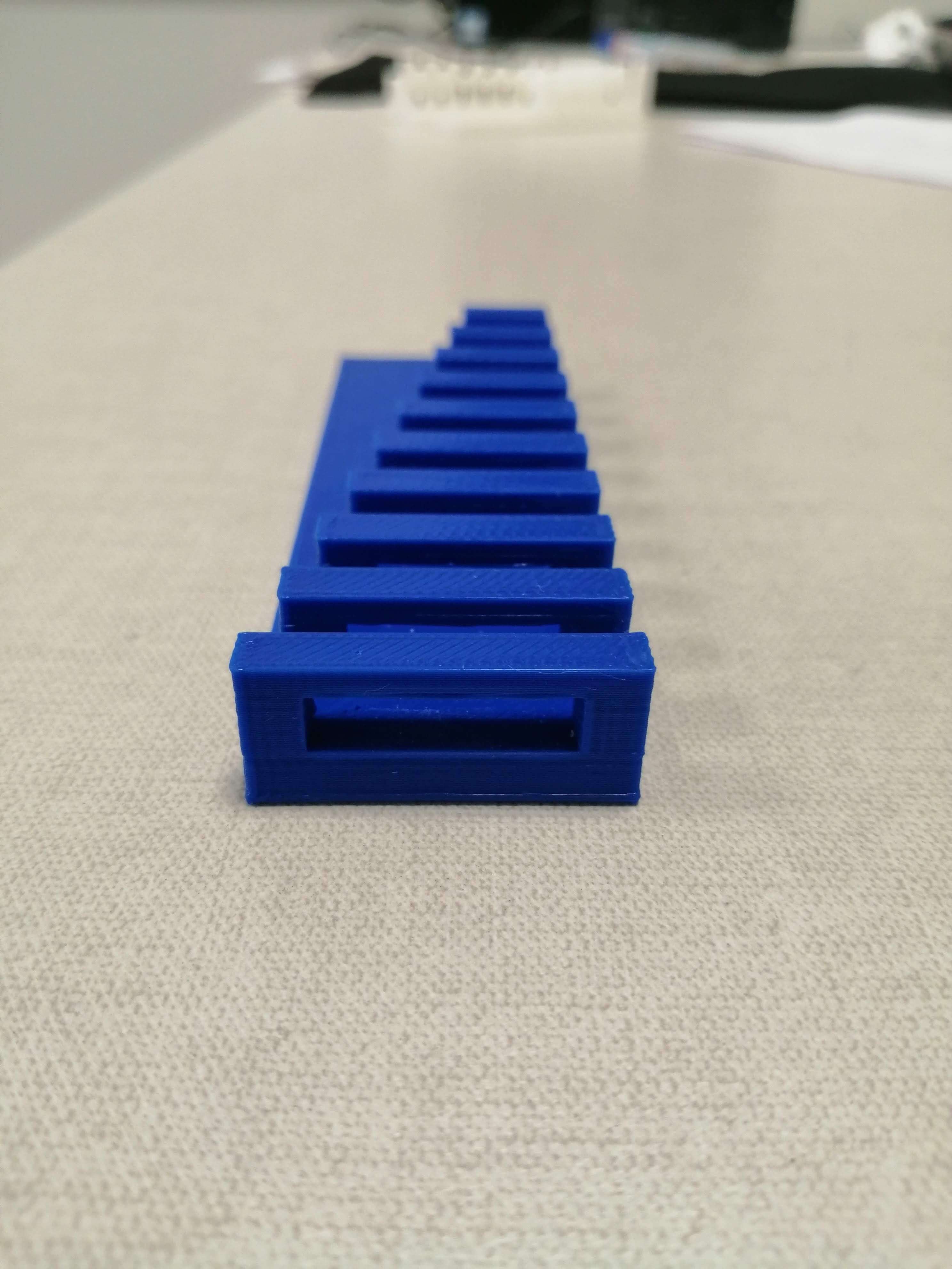
At 14mm distance we can already appreciate the effects of bridging on our part and as the distance increases in the same way the overhang does, we determine that the optimal distance for our printer is 12mm.
What I’ve learned
Maybe we are used to connecting an inkjet printer and starting to print, that doesn’t apply to a 3D printer, the slightest thing can affect the pieces, starting with the leveling of the bed, the humidity in the filament, etc. That is why I consider that these tests helped to identify the operation of our machine.
Individual assignment
Design and 3D print
For this assignment we must design a part that can be manufactured through an FDM process and should be impossible to manufacture through a subtraction process, there are different models available on the internet such as chainmails, springs and print-in-place model. As the assignment indicates it must be something small, so I decided to design a cube with the FABLAB symbol that contains a sphere inside like a rattle.
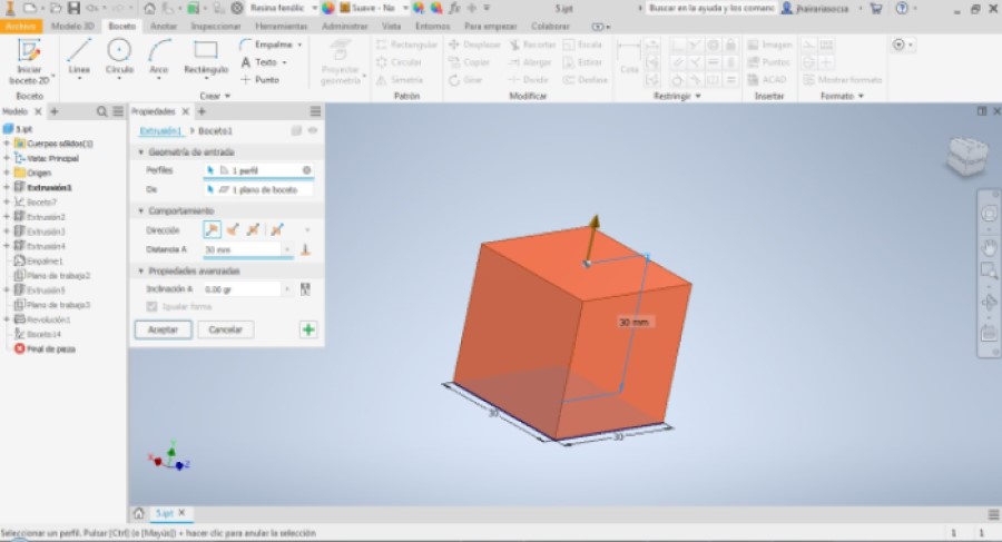
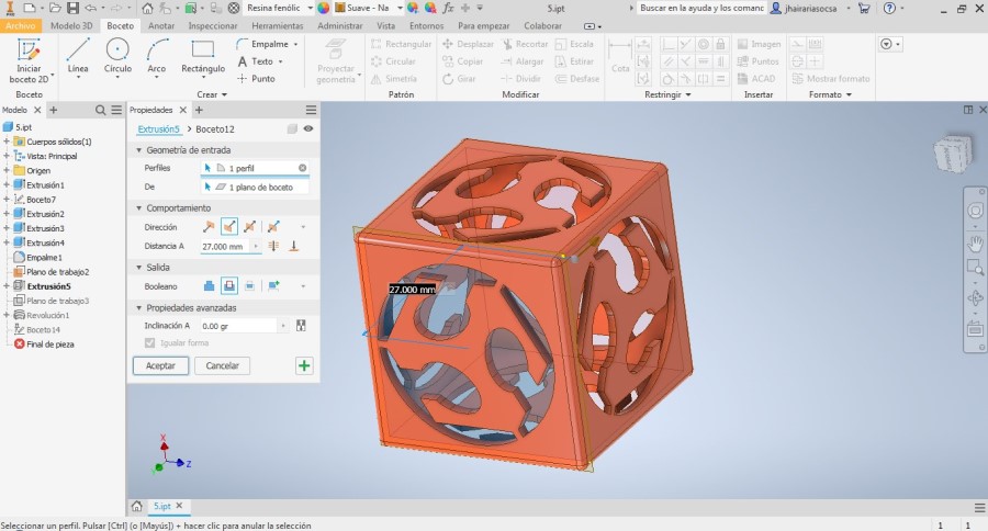
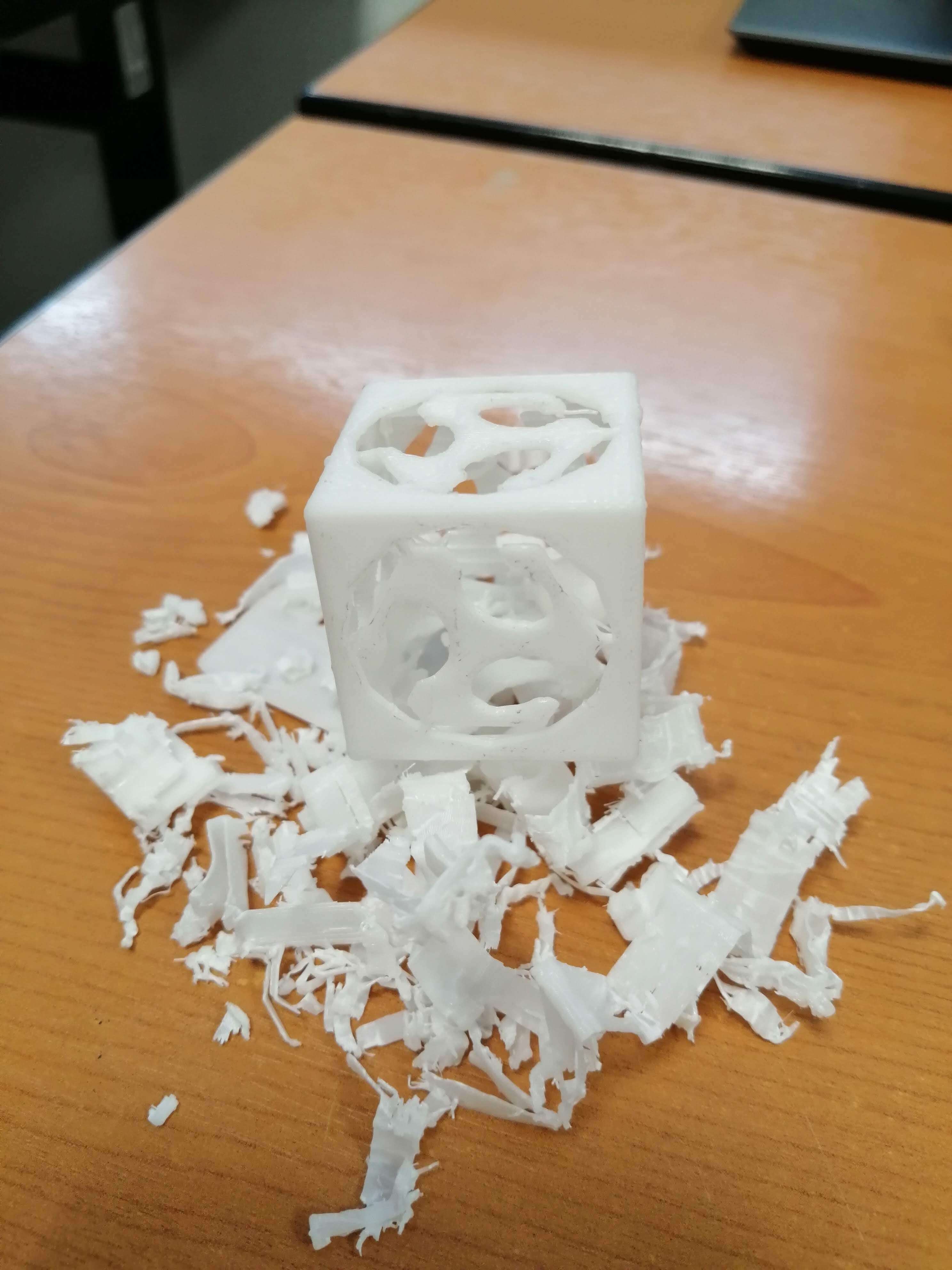
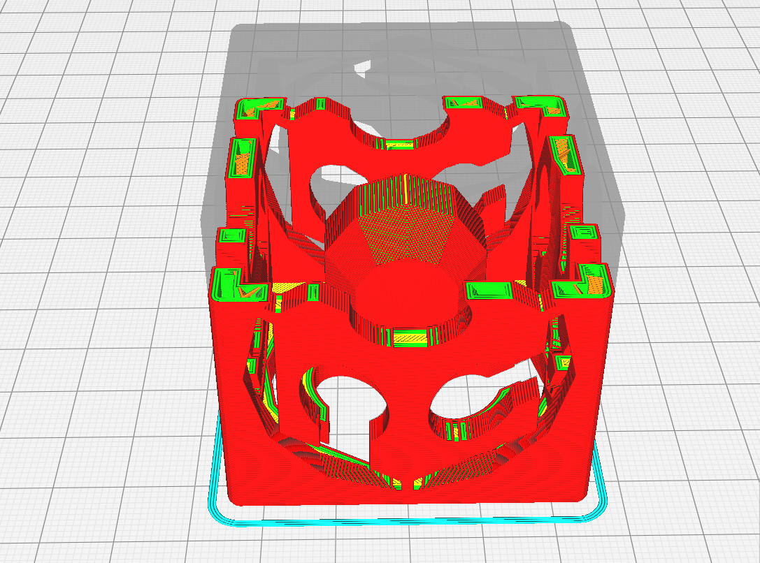
I used Inventor to design the whole piece, I will not go into many details, but I’ve attached screenshots with the steps that I followed to elaborate it, I think that I got carried away by the idea, since at the time of printing it, I did not consider the amount of supports that were necessary to correctly print the piece and in the end remove all the supports turned out to be a very tedious process, even damaging the piece, so I had to print it again, I still feel that it served to understand some parameters that I had left aside, in the final image you can see the amount of supports that were necessary to print the piece, for a next occasion perhaps turning it 45 degrees could achieve a piece with a cleaner finish.
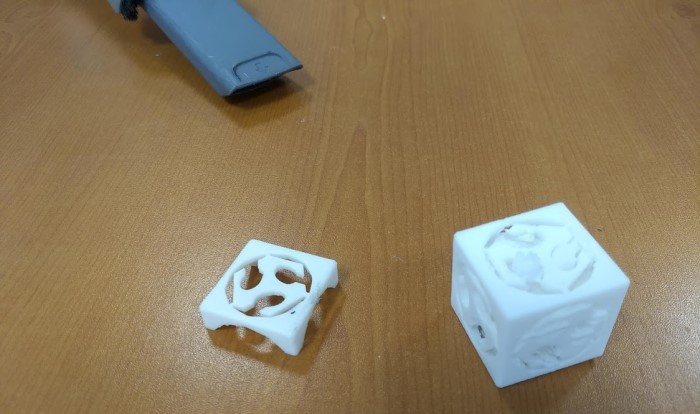
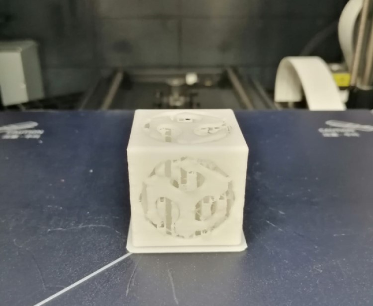
As can be seen in the images, this object could not be elaborated through a subtraction process because it is a cube with a hollow interior and additionally it has a sphere inside, we positioned the sphere in the center and thanks to the supports we were able to print it, since it had no other type of hub joint.

Scan and 3D print
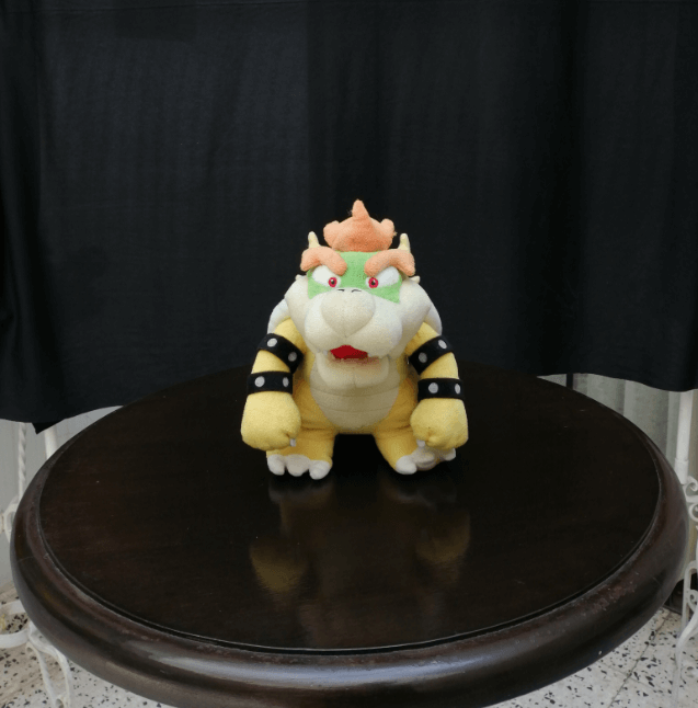
I decided that for this assignment I will use the photogrammetry technique provided by Meshroom and Meshmixer for the subsequent processing of the piece. First I have to select the object that I plan to scan, in this case a Bowser plush, a Mario Bros character, then the most important thing is to choose a place with adequate lighting and a background that contrasts with the object, it is important to remember that we have to turn around the object to take the photos and the object should not change its position, otherwise this technique will not work.
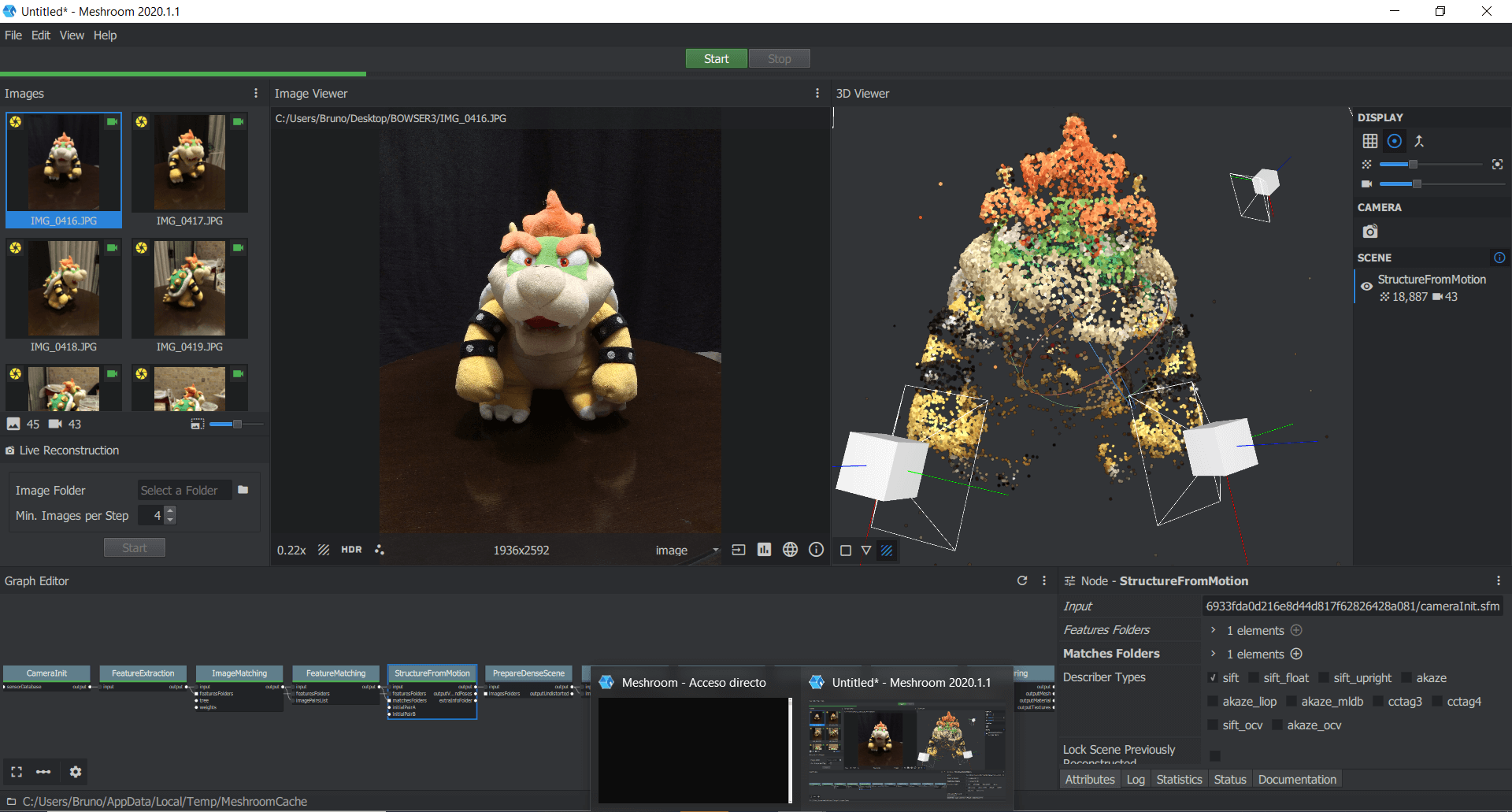
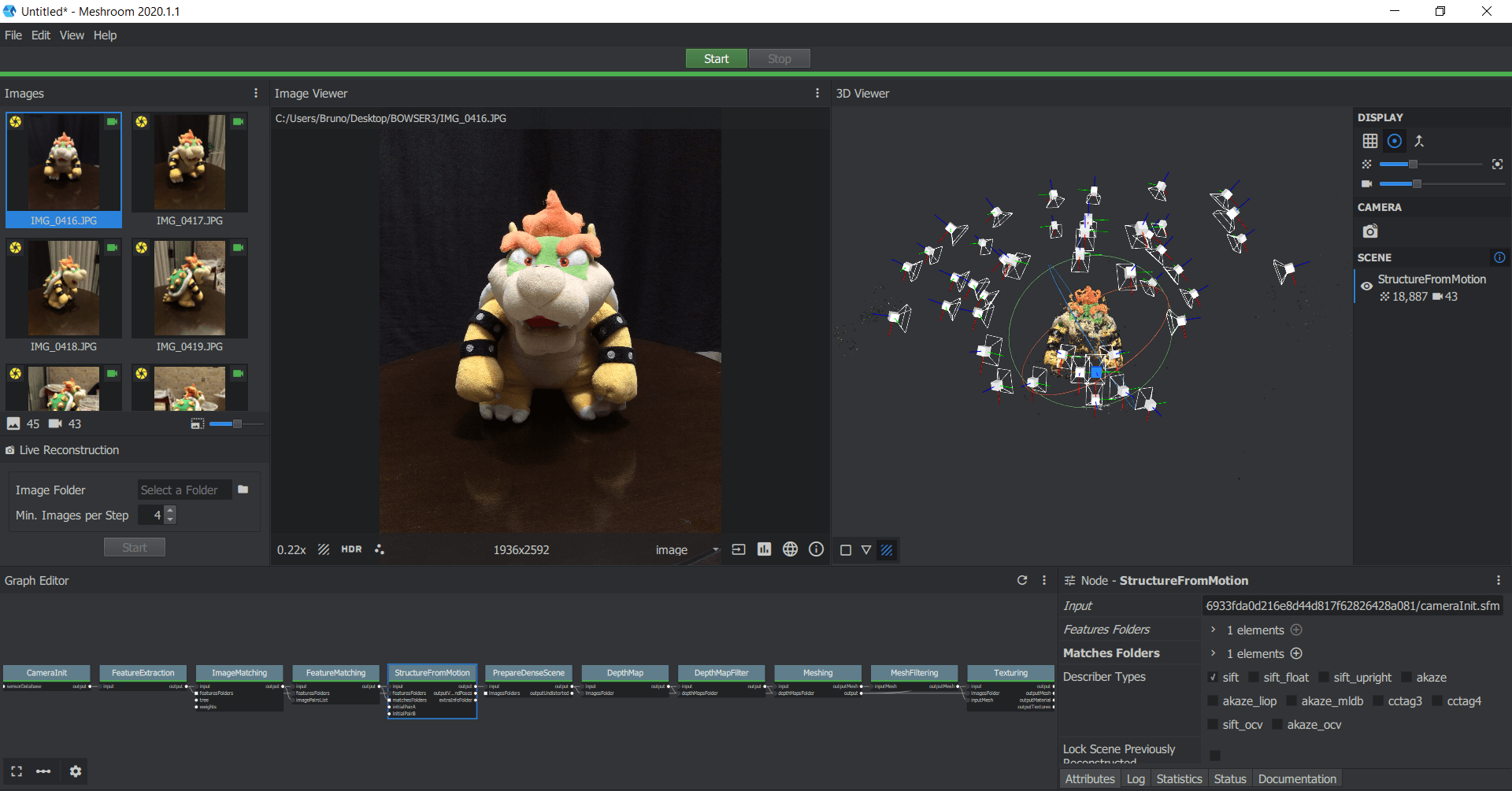
Once the test subject was placed in the correct position, I began to take photos from different angles, in total there were 45 photos, which I then proceeded to upload to Meshroom, a tip to make better use of the time, is not to directly click the Start button, since it will execute the whole processing process, to check if the object was recognized by the software we can click on StructureFromMotion and press Compute, we will have a preview of the work and then we can decide whether to continue with the processing or enter more photos.
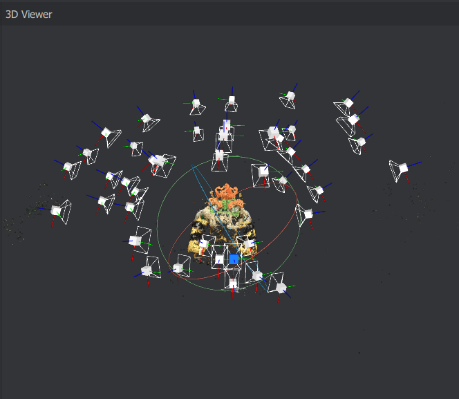
When I was sure that everything was as I wanted, I started with the complete processing that took a lot of time and consumed many resources of my PC, I could compare it with a rendering process, when it finally finished it generated a folder that stored each of the steps and their respective .obj file, so I looked for the Texturing obj file.
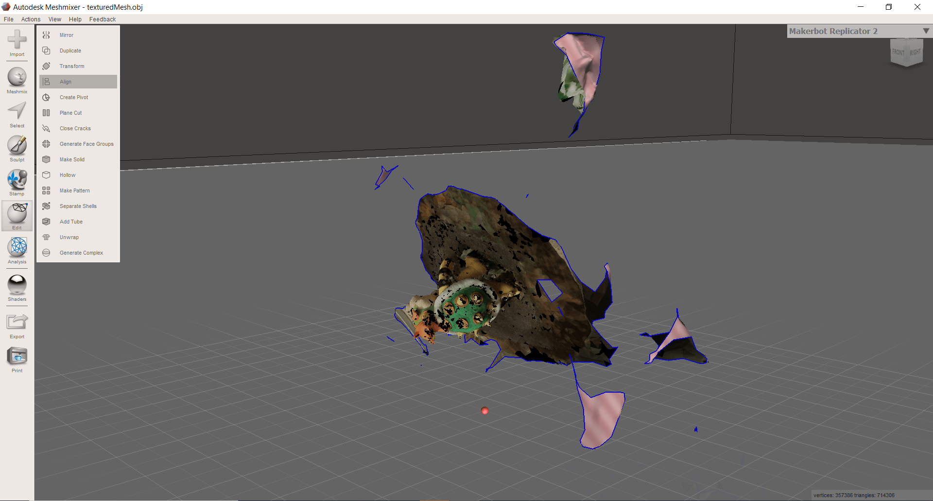
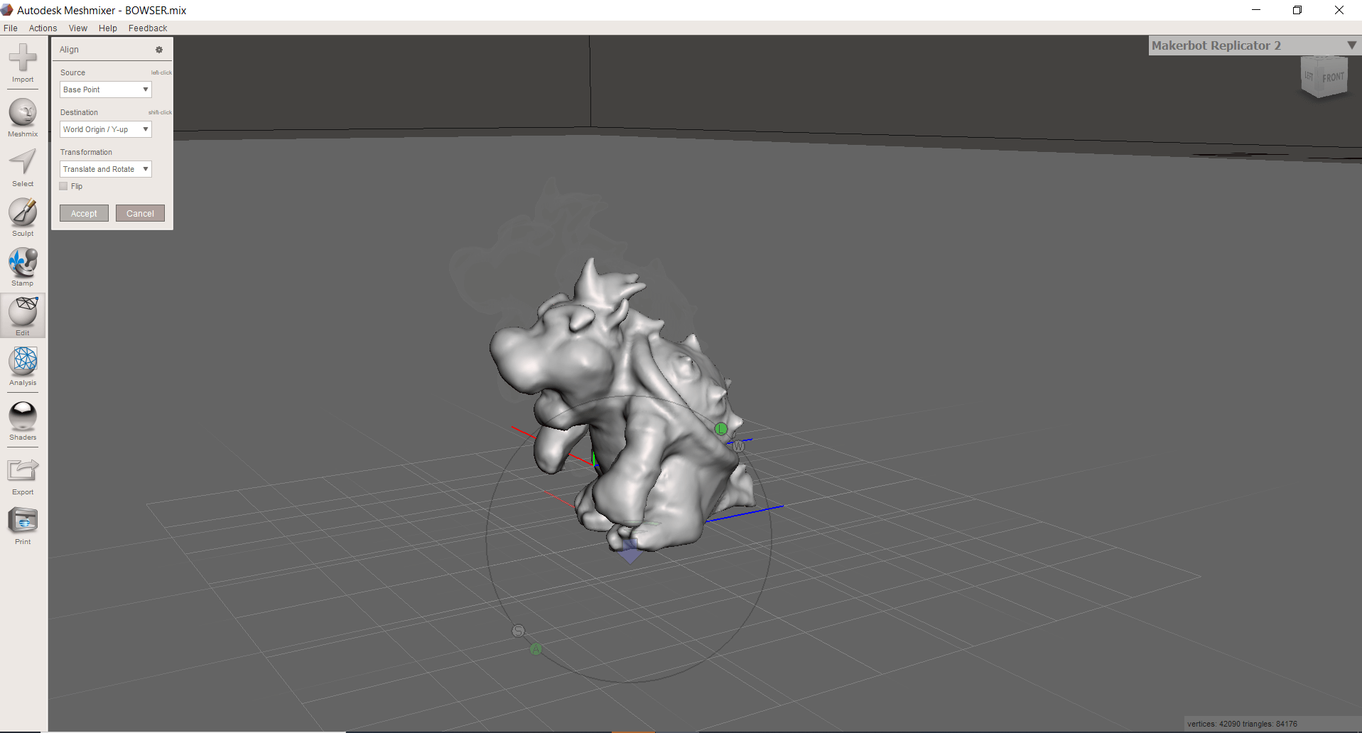
When I uploaded the file to Meshmixer I could see that there was a lot of work to be done, starting with aligning the part, so the first thing was to align it and then carefully start to cut out all the parts that I do not want printed.
![]()
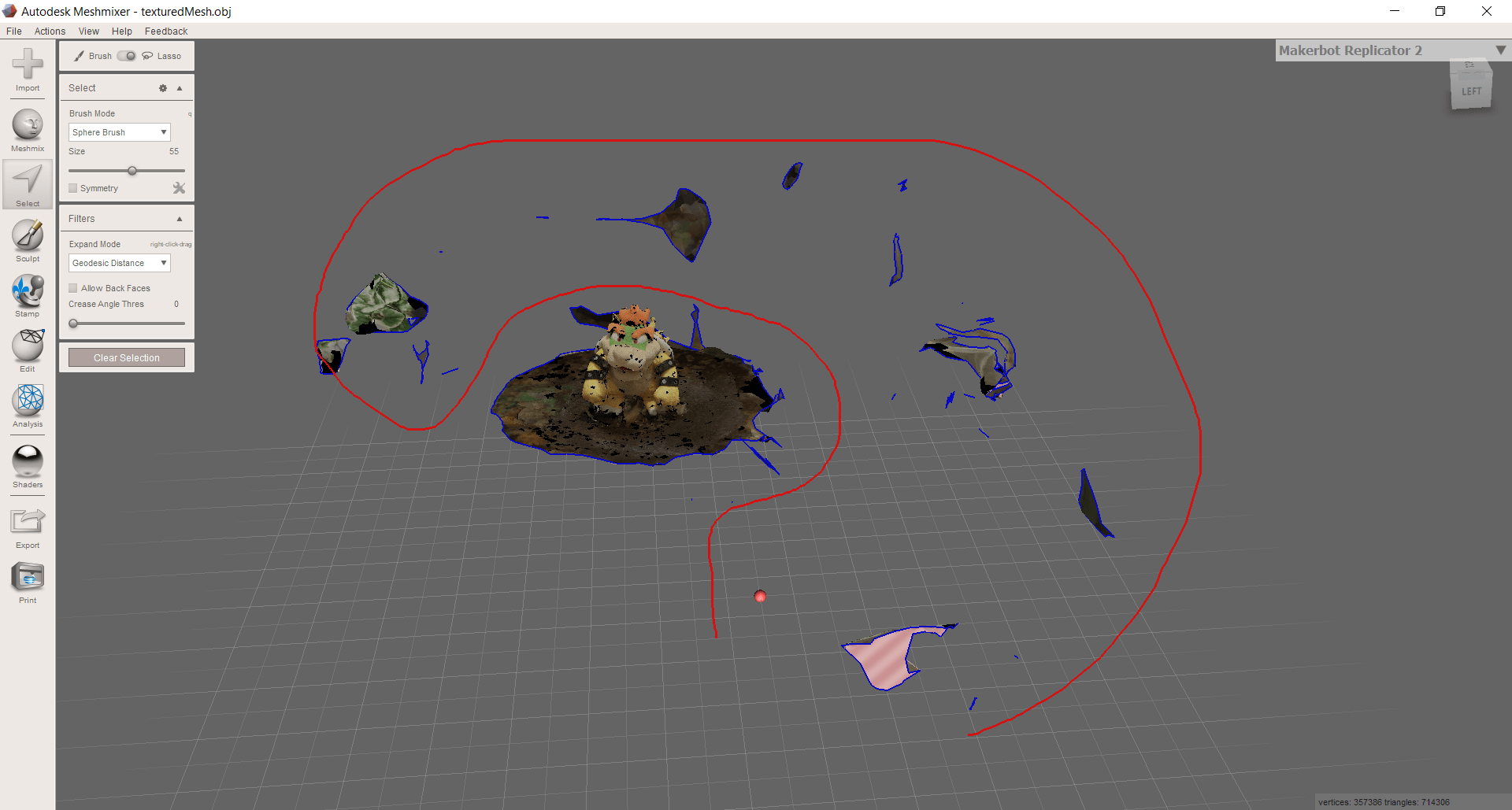
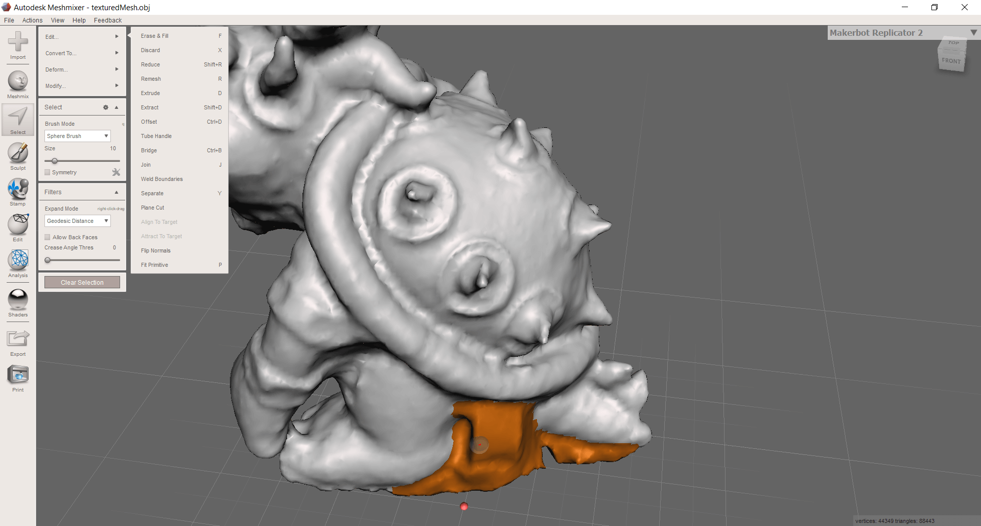
The process of eliminating the parts that would not be printed took a bit of time and care, but I managed to select the vast majority of parts that I did not want to be printed, thanks to the Select tool I circle everything that I did not want and eliminated.
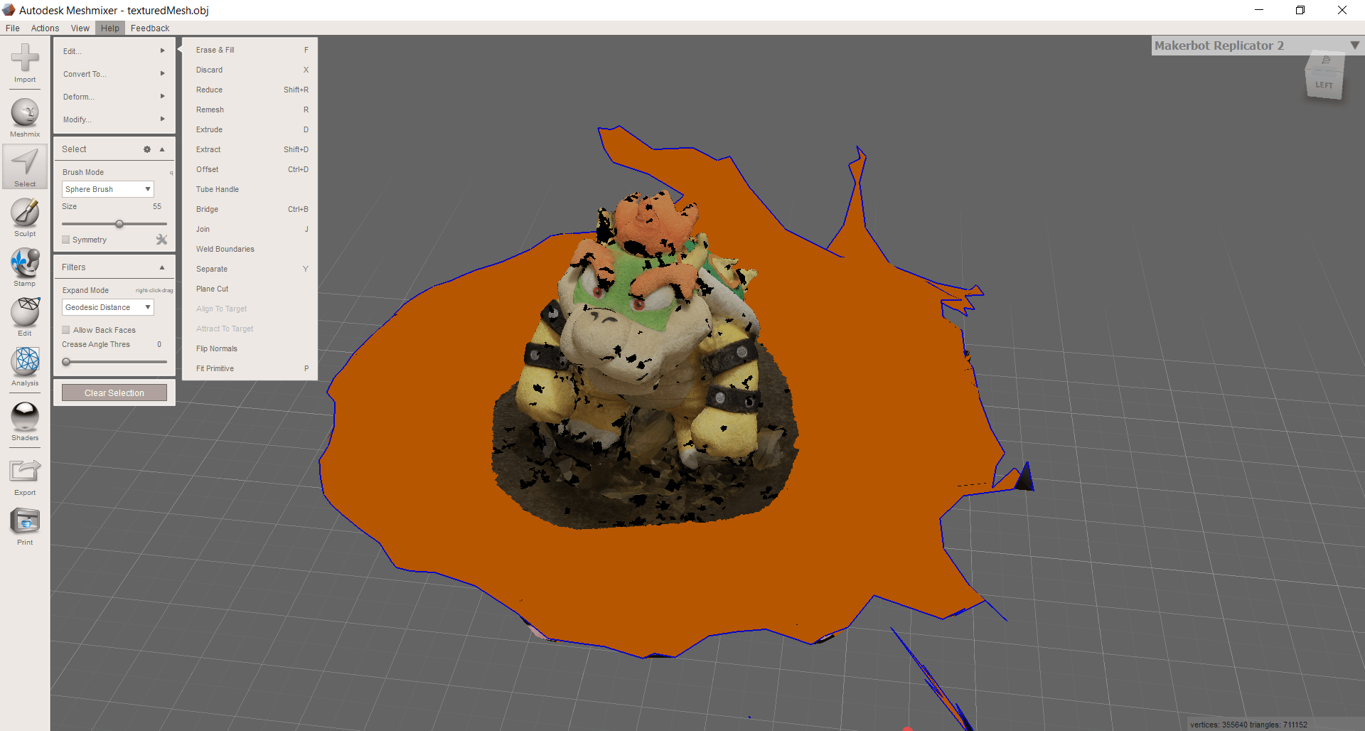
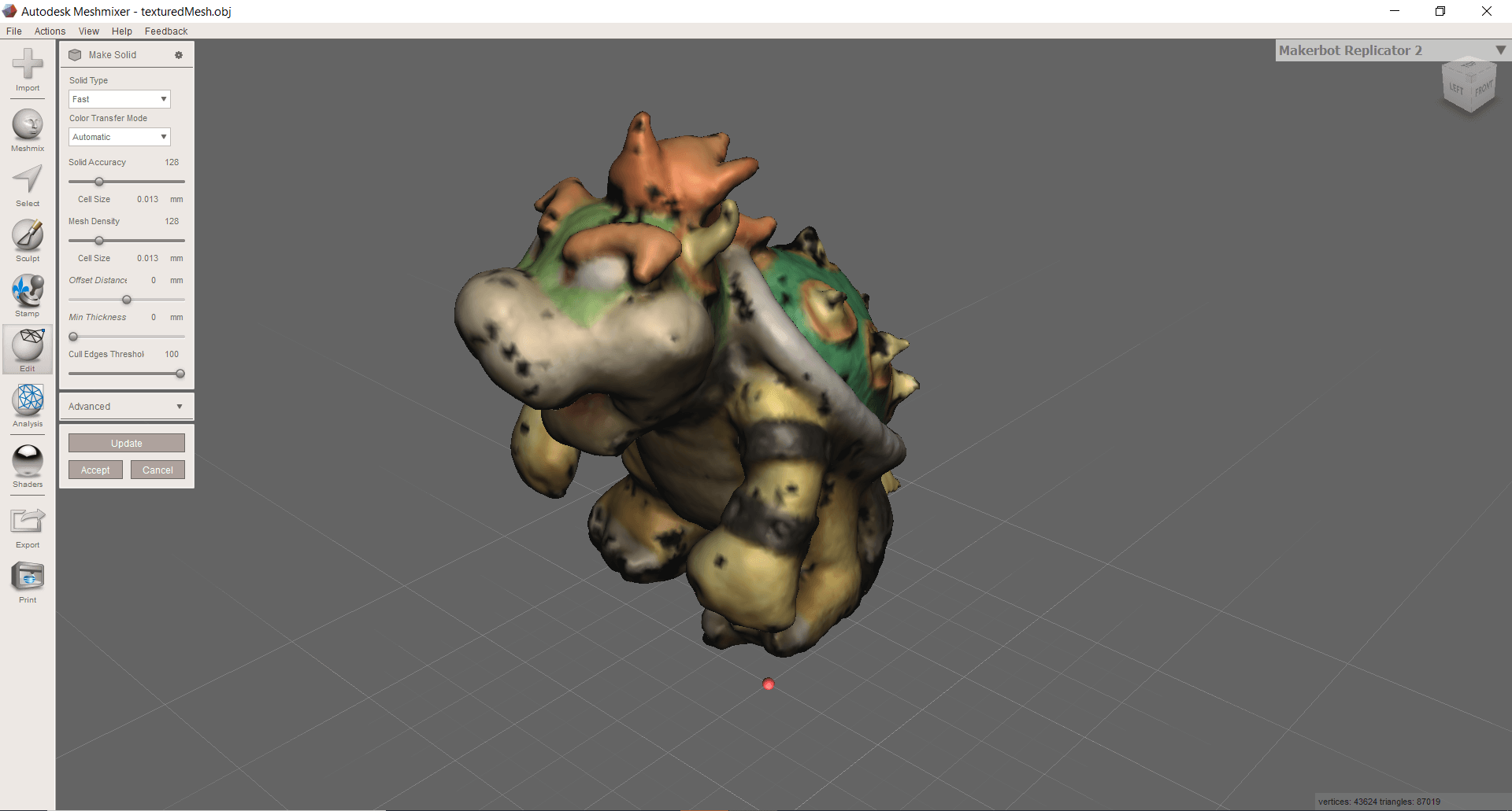
We end up with a piece that is empty inside, what we must do now is make it solid, in order to later be able to make changes in the shape of the object, since it can be seen that there are parts that did not work out well, including the part of the label was detected as a solid, we will modify all that later. We select the part and click on the option Edit -> Make solid.
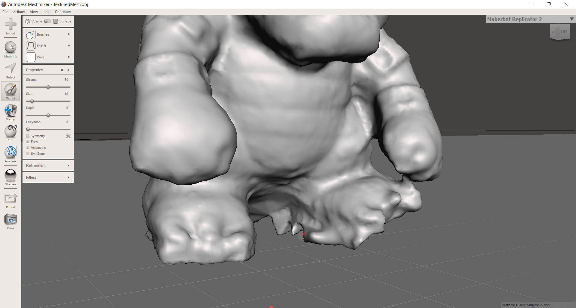
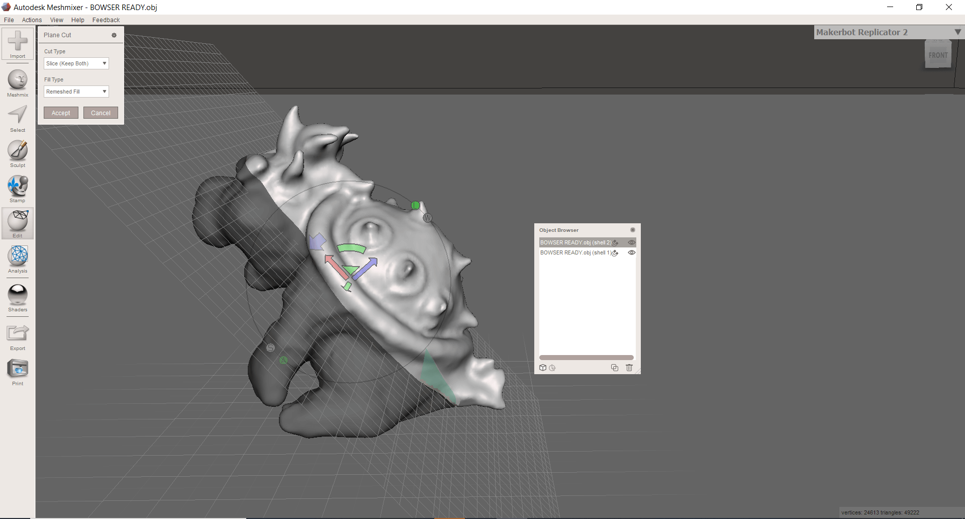
The process that follows is going to take time, but very important if we want our piece to come out as similar to the original model, we will use the sculpting tools to make modifications to the shape of the object, as well as eliminate imperfections using the selection tool, it is important have the model nearby to check that the changes we make bring us closer to the original model.
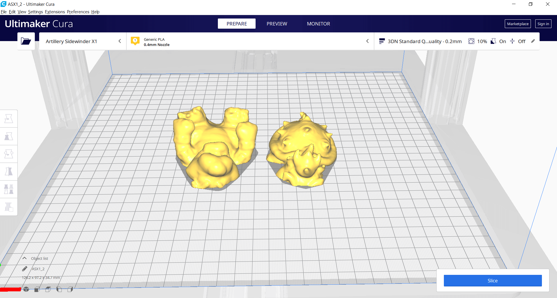
We can take advantage of one of the most well-known Meshmixer options, that is dividing pieces, either because they are too large to fit into our printing area or because a large number of supports are required to print the piece (as is our case), so we will divide our Bowser into 2 pieces to be able to print it without supports and then glue it on.
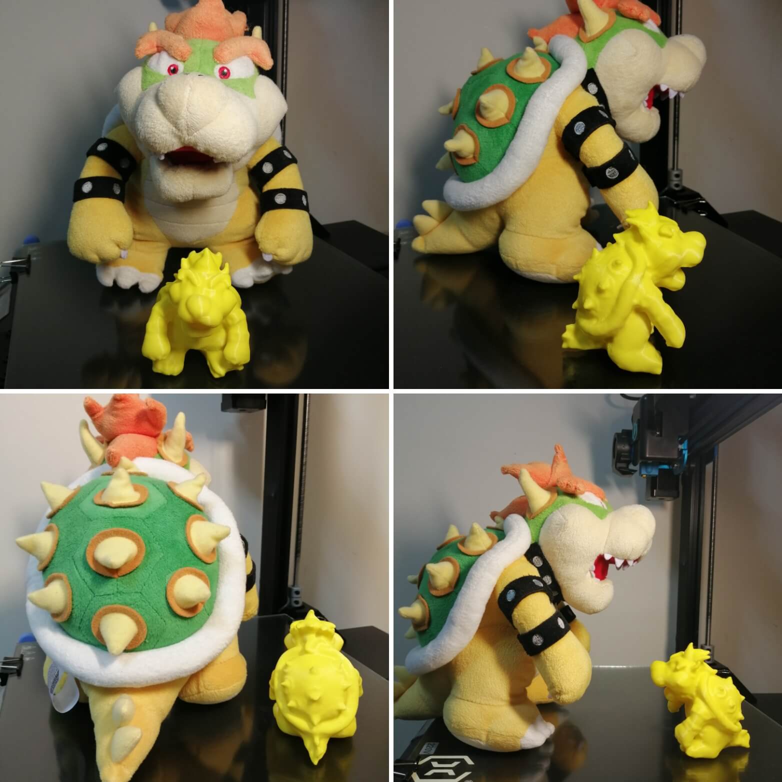
A week ago I did not know anything about the photogrammetry technique, this assignment helped me to learn about it, you do not need expensive equipment to apply it, it has its limitations, but I still found it very interesting, I am satisfied with the result, maybe I will apply it again but paying more attention to the details so that in the end the piece is as I wish. Meshmixer is a very useful tool for editing .obj and .stl files. It has a variety of tools and thanks to this I was able to repair my scanned piece, I attach a comparative shot of the final result vs. the original one.
You can download the files below:
Week Assessment
During this week, have I :
-
[ ] Linked to the group assignment page ? Yes, I did.
-
[ ] Explained what I’ve learned from testing the 3D printers ? Yes, have a look at What I’ve learned.
-
[ ] Documented how I’ve designed and made my object and explained why it could not be easily made subtractively ? Yes I did, maybe the idea had another shape in my head, but this assignment helped me understand some things that I should take into consideration when designing pieces.
-
[ ] Documented how I scanned and prepared an object for 3D printing? Yes, have a look at Scan and 3D print.
-
[ ] Included my original design files for 3D printing ? I did, I hope they are useful for other people or maybe they can improve them.
-
[ ] Included hero shots of my work ? I took as many photos as possible as I am very satisfied with the end result.