11. Input devices
This assignment focuses on learning how to link an input device with our microcontroller and understand how that reading is related to the measured magnitude, we must understand the resolution that our microcontroller provides in order to better understand the value that it will show us, I hope this week can do everything I have in mind.
Assignment
group assignment:
- probe an input device’s analog levels and digital signals
individual assignment:
- measure something: add a sensor to a microcontroller board that you have designed and read it
Group assignment
Due to the restrictions due to COVID-19 I do not have constant access to the laboratory (I will not be able to use the oscilloscope) so for the moment I will use the serial port of an Arduino UNO to be able to visualize the values that my LDR sensor provides with the help of Processing. This will also help me understand the values that it generally provides in the environment and will allow me to establish the conditionals for my programming.
Analog level measurement
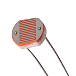
What are photoresistors?
Photo resistors, also known as light dependent resistors (LDR), are light sensitive devices most often used to indicate the presence or absence of light, or to measure the light intensity. In the dark, their resistance is very high, sometimes up to 1MΩ, but when the LDR sensor is exposed to light, the resistance drops dramatically, even down to a few ohms, depending on the light intensity. LDRs have a sensitivity that varies with the wavelength of the light applied and are nonlinear devices. They are used in many applications but are sometimes made obsolete by other devices such as photodiodes and phototransistors. Some countries have banned LDRs made of lead or cadmium over environmental safety concerns.
Arduino code
The Arduino code is simple, we only have to make the constant reading of pin A0 and very important to enable serial communication at 9600 Bauds, we must also connect the LDR as shown in the image below with a 10K resistor between the signal and GND.

// This sketch reads analog data on A0 and sends it out to
// the serial port with each sample terminated by a new line "\n"
// The Processing sketch can then parse the data and plot it graphically.

void setup() {
  Serial.begin(9600);
}

void loop() {
  Serial.print(analogRead(A0));
  Serial.print("\n");
  delay(5);
}
Processing code
Instead, the Processing code will be more complex because, as its name indicates, it will process the data received through the serial COM port (it is super important to define the port to which the Arduino UNO is connected in the following instruction myPort = new Serial (this, “COM6”, 9600);). We can also modify parameters such as the color of the line (Stroke color) and the thickness of the line (Stroke wider), if we do everything correctly then we will be ready to visualize a graph with the values obtained by the LDR sensor.
import processing.serial.*;

Serial myPort;        // The serial port
float inByte;         // Incoming serial data
boolean newData = false;
int xPos = 1;         // horizontal position of the graph

//Variables to draw a continuous line.
int lastxPos=1;
int lastheight=0;

void setup () {
  // set the window size:
  size(600, 400);

  myPort = new Serial(this, "COM6", 9600);

  // A serialEvent() is generated when a newline character is received :
  myPort.bufferUntil('\n');
  background(0);      // set inital background:
}
void draw () {
  if (newData) {
    //Drawing a line from Last inByte to the new one.
    stroke(0,255,255);     //stroke color
    strokeWeight(2);        //stroke wider
    line(lastxPos, lastheight, xPos, height - inByte);
    lastxPos= xPos;
    lastheight= int(height-inByte);

    // at the edge of the window, go back to the beginning:
    if (xPos >= width) {
      xPos = 0;
      lastxPos= 0;
      background(0);  //Clear the screen.
    }
    else {
      // increment the horizontal position:
      xPos++;
    }
   newData =false;
 }
}

void serialEvent (Serial myPort) {
  // get the ASCII string:
  String inString = myPort.readStringUntil('\n');
  if (inString != null) {
    inString = trim(inString);                // trim off whitespaces.
    inByte = float(inString);           // convert to a number.
    inByte = map(inByte, 0, 1023, 0, height); //map to the screen height.
    newData = true;
  }
}
Here you can see the final result, trying to imitate Neil’s video format :), we can see how the resistance increases when we cover the sensor and in the same way the resistance decreases when it is exposed to light.


Digital level measurement
Button and pull-down resistor
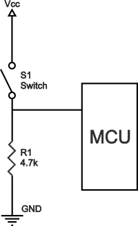
Pull-down resistors work in the same manner as pull-up resistors, except that they pull the pin to a logical low value. They are connected between ground and the appropriate pin on a device. An example of a pull-down resistor in a digital circuit can be seen in the figure. A pushbutton switch is connected between the supply voltage and a microcontroller pin. In such a circuit, when the switch is closed, the micro-controller input is at a logical high value, but when the switch is open, the pull-down resistor pulls the input voltage down to ground (logical zero value), preventing an undefined state at the input. The pull-down resistor must have a larger resistance than the impedance of the logic circuit, or else it might be able to pull the voltage down by too much and the input voltage at the pin would remain at a constant logical low value – regardless of the switch position.
Arduino code
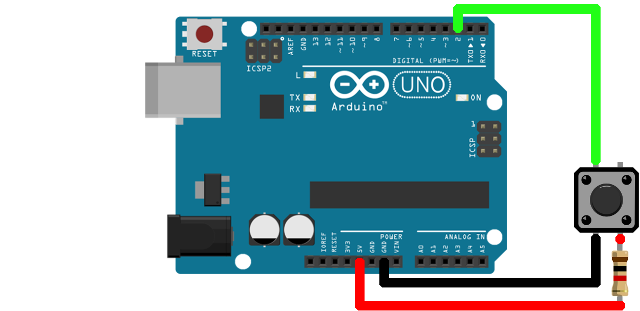
The Arduino code is simple, we only have to make the constant reading of pin D13 and very important to enable serial communication at 9600 Bauds, we must also connect the button as shown in the image below with a 10K resistor between the signal and GND.
// This sketch reads digital data on D13 and sends it out to
// the serial port with each sample terminated by a new line "\n"
// The Processing sketch can then parse the data and plot it graphically.

void setup() {
  Serial.begin(9600);
}

void loop() {
  Serial.print(digitalRead(13));
  Serial.print("\n");
  delay(5);
}
Processing code
Instead, the Processing code will be more complex because, as its name indicates, it will process the data received through the serial COM port (it is super important to define the port to which the Arduino UNO is connected in the following instruction myPort = new Serial (this, “COM6”, 9600);). We can also modify parameters such as the color of the line (Stroke color) and the thickness of the line (Stroke wider), if we do everything correctly then we will be ready to visualize a graph with the logic values obtained by the button.
import processing.serial.*;

Serial myPort;        // The serial port
float inByte;         // Incoming serial data
boolean newData = false;
int xPos = 1;         // horizontal position of the graph

//Variables to draw a continuous line.
int lastxPos=1;
int lastheight=0;

void setup () {
  // set the window size:
  size(600, 400);

  myPort = new Serial(this, "COM6", 9600);

  // A serialEvent() is generated when a newline character is received :
  myPort.bufferUntil('\n');
  background(0);      // set inital background:
}
void draw () {
  if (newData) {
    //Drawing a line from Last inByte to the new one.
    stroke(0,255,50);     //stroke color
    strokeWeight(2);        //stroke wider
    line(lastxPos, lastheight, xPos, height - inByte);
    lastxPos= xPos;
    lastheight= int(height-inByte);

    // at the edge of the window, go back to the beginning:
    if (xPos >= width) {
      xPos = 0;
      lastxPos= 0;
      background(0);  //Clear the screen.
    }
    else {
      // increment the horizontal position:
      xPos++;
    }
   newData =false;
 }
}

void serialEvent (Serial myPort) {
  // get the ASCII string:
  String inString = myPort.readStringUntil('\n');
  if (inString != null) {
    inString = trim(inString);                // trim off whitespaces.
    inByte = float(inString);           // convert to a number.
    inByte = map(inByte, 0, 1, 0, 300); //map to the screen height.
    newData = true;
  }
}
Here you can see the final result, we can see how the value turns to HIGH when we press the button and in turns LOW when when we don’t press it.

Individual assignment
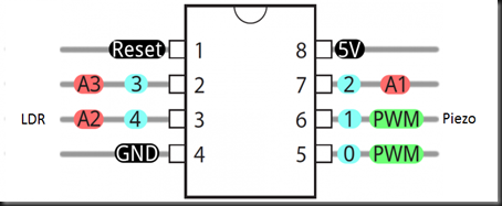
For this assignment I am going to use the board I made in the previous session, since it has a direct connector to an analog pin of the ATtiny85 and it will be ideal for reading the LDR, I will make a simple sketch in the Arduino IDE and use my Arduino UNO as ISP programmer. First I will focus on developing the code, for this I will connect the LDR sensor to pin A2 of the ATtiny85 together with a 10K resistance between signal and ground, I will also use the Led connected to pin 1 of the ATtiny85, to make the application more interesting, I will control the brightness intensity of the Led according to the amount of light available, simulating an intelligent lighting system using the “map” instruction that will convert my analog values from 0 - 1023 to PWM values of 0 - 255.
Source code
const int boton = 3;
const int led = 1;
int buttonState = 0;
int analogPin = A2;
int val = 0;

void setup()
{
  pinMode(led, OUTPUT);
  pinMode(boton, INPUT);

}

void loop()
{
  val = analogRead(analogPin);    // read the input pin
  val = map(val, 0, 1023, 255, 0);
  analogWrite(led, val);
}
Signal problems
After getting everything ready for testing and being sure that my code was going to work, I made the connection of the board to program it, everything worked correctly being connected to the ISP programmer (Arduino UNO) but at the moment I remove the cable from the programmer and turned the power ON of the board with the built-in CR2032 battery, the circuit did not behave the same, it seemed like a weird problem, I started using other LDRs but the problem persisted, I was about to give up and then I remembered that I was using a 10K resistor as it is generally used for reading sensors in 5V microcontrollers (there was the problem), because my circuit works at 3.3V which means that I had to reduce the value of that resistance to be able to use my sensor correctly as a voltage divider, swap the 10K resistor for a 1K resistor and the problem was fixed, 4.7K could work too.

Testing the code

You can download the files below:
Week Assessment
During this week, have I:
-
[ ] Linked to the group assignment page ? Yes, I did.
-
[ ] Documented what I’ve learned from interfacing an input device to microcontroller and how the physical property relates to the measured results ? I understood the principle of operation of an LDR and how its resistance varies according to the intensity of the light
-
[ ] Documented my design and fabrication process or linked to previous examples ? I did the same last assignment Embedded programming, but I still attached the design files.
-
[ ] Explained the programming process I used ? Nothing fancy, just the usual an Arduino as ISP programmer and a bit of Processing.
-
[ ] Explained problems and how I fixed them ? I must admit that the voltage divider brought me a lot of problems.
-
[ ] Included my original design files and source code ? Yep.
-
[ ] Included a hero shot/video of my board ? Trying to mimic the format of Neil’s videos.