“it's a long and winding road...”
The Beatles
Progress Report
Overall Design
Choice of the components...
Faced with the mountain of information to digest, I've to make decision as to on which key areas to focus my attention and learning efforts. In doing that, one thing I have to admit to have overlooked is the scrutiny of selecting each component for the project.
With what I know now, the components that require the most attention for this project are the stepper motors and the battery(ies); the second flows from the first as I have found out that stepper motors are not very efficient: they tend to give a poor ratio of torque to power consumption. It is probably a good idea to consider adding a reducer between motor and wheel as the speed is not an issue.
Chassis Design
Material structure and assembly...
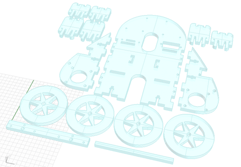
The body is made from a laser-cut 4mm thick sheet of plexiglass. The different parts of the body are assembled in three different ways:
- snap joints
- Screw tightened finger joints [captive square nut joints]
- rubber bands (actually there to hold in place motors batteries or other elements)

Electronics Design
An Arduino board is requested to drive two stepper motors and a servo motor.
The board is based on the Mat2ino which itself is an offspring of Barduino. The board is designed to use only the ports that are required by DooD (4 pins for each motor, 1 pin for the servo, 3 pins for reading the accelerometer data)
Each motor driver has its own shield which is directly fed 11.1 V. from the 3 3.7V Lithium ion that have been connected in series. In my original design relied on a single regular 9V. battery but this provided way too little VAH for DooD to run long enough for a demo.
The shape of the board is designed to adapt to the shape of DooD's body and holes are drilled to match the screw hole matrix on DooD's body. The board is simply fastened to the body with three nylon screws.
\A bug I discovered on demo day was the voltage regulator I used did not supply enough current to power my pen lift servo. The reason I did not figure it out before demo day (apart from the fact that I did not progress with comfortable time schedule) is that I did my testing with the FTDI cable plugged in to monitor the program and spare the battery, and decided to cut the umbilical cord on demo day...
Downloadables
Main Board
[ download MAIN BOARD SCHEMATIC file: "Dood_v06.sch" ]
[ download MAIN BOARD LAYOUT file: "Dood_v06.brd" ]
[ download MAIN BOARD TRACES file: "DooD_traces_v06.png" ]
![[ download MAIN BOARD TRACES file: "DooD_traces_v06.png" ]](downloadables/DooD_traces_v06.png)
[ download MAIN BOARD CUT-OUT file: "DooD_cut_v06.png" ]
![[ download MAIN BOARD CUT-OUT file: "DooD_cut_v06.png" ]](downloadables/DooD_cut_v06.png)
Motor Driver Shield
[ download STEPPER DRIVER SCHEMATIC file: "StepperDriver_v02.sch" ]
[ download STEPPER DRIVER LAYOUT file: "StepperDriver_v02.brd" ]
[ download STEPPER DRIVER TRACES file: "StepperDriver_v02_traces.png" ]
![[ download STEPPER DRIVER TRACES file: "StepperDriver_v02_traces.png" ]](downloadables/StepperDriver_v02_traces.png)
[ download STEPPER DRIVER CUT-OUT file: "StepperDriver_v02_cut.png" ]
![[ download STEPPER DRIVER CUT-OUT file: "StepperDriver_v02_cut.png" ]](downloadables/StepperDriver_v02_cut.png)
Battery coupler
[ download 3.7V. x 3 Battery coupler SCHEMATIC file: "Battery_coupler.sch" ]
[ download 3.7V. x 3 Battery coupler LAYOUT file: "Battery_coupler.brd" ]
Accelerometer Shield
TBA
Mechanical Design
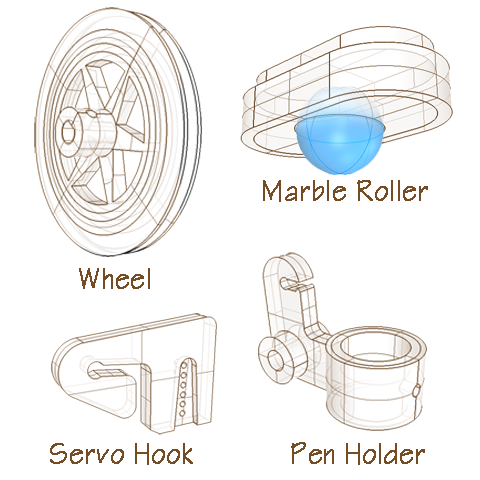
3D printed components...
- The wheels
- The pen holder and lever
- The pen lift hook
- The marble cradle (used as omni-direction wheel)
- The servo motor cradle
For the wheels I found in a local hardware store a couple of rubber torric joints (O-rings) of 60mm diameter and 3mm cross section diameter. As the rubber can stretch a little I will easily get to my desired overall wheel diameter of 63,662mm (this specific diameter will insure a convenient traveled distance of 1mm per step.)
The O-ring tires prove to lack adherence on the surfaces I have tested DooD. With the torric joint tires, to limit the skid I need to apply a load on DooD.
Downloadables
[ download Wheel STL file: "Wheel_63_66mm_v4.stl" ]
[ download Marble Roller STL file: "Marble_roller.stl" ]
[ download Pen Lift STL file: "Pen_lift_v2.stl" ]
[ download Servo Hook STL file: "Servo_Hook.stl" ]
[ download Servo Cradle STL file: "ServoCradle_v2.stl" ]
Software Development
At this stage the programming has been performed on Arduino platform using both the Arduino Stepper Library and the Arduino Servo library. I wanted to write my own library code for the motors of Dood, because the stepper library handles one motor at a time and I wanted to control both motors simultaneously. My attempt has not worked yet as I'm lacking knowledge in Object oriented programming so I went back to using the stepper library in this beta version.
The code has been the last element to be worked on and still needs major enhancements
Downloadables
[ download ARDUINO SKETCH file: "DooD_v2_0.ino" ]
Interface Design
This first prototype lacks an easy to use way to communicate with it and send it instructions. At the current stage of development we load a program in the processors that contains both the methods and the content (the instructions). In later stage we should be able to pass a text file which contains only the instructions, DooD will have permanently loaded in the chip the code that lets it interpret the input file.
Ideally this file should be transmitted either wirelessly or through a external memory device (memory card, memory stick).