Modules 15a-15b – mechanical design, machine design
Class
In class we've been flying through a number of concept about how solids interact with one-another and with their environements. All concepts that are useful if not necessary to make a good machine design.
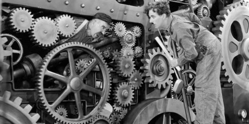
It's all very interesting and I'm tempted to find a few books that go more in depth into the subject, but I don't believe that it is the priority for now, so I'll remain slightly clueless. Fr now, I do feel nearly as useful in that subject matter as Charlie Chaplin in "Modern Times", but I'm here to learn.
The rest of the class is pretty much about gowing down the McMaster inventory, and having a brief introduction to how useful each can be and the variety in each category... Hmm... McMaster: another good read that!

The Assignment
do the mechanical design for your final project.
.
The idea
OK, call it procrastination, but I sincerely do not find the time to make serious advance in my final project. The design is still what is was when I produced the first assignment, and there is little mechanical parts to the design ( I'm planning to have the motor drive the wheels directly with no transmission part appart from a shaft extension, I suppose I need to figure out a mechanism for the pen up and down motion (my idea for that is a simple servo motor that activates a lever of some sort).
So short of any good mechanical design part within my final project, I decided to try and do something with gears... Ok so now I might be flirting with procratination.
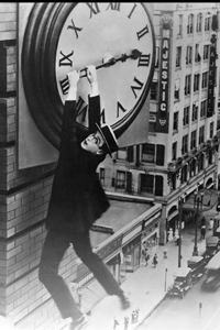
The first thing that comes to mind, when you need to come up with an idea for an aparatus with gears is a clock. So I'm going to try may hands at making some kind of a clock.
T...
The Design
Basic Concept
The idea is to get my stepper motor from Output Devices week and having it drive the second's hand, and then let the gears work it out from there.
Designing the Gears
I do'nt know the first thing about gears, just that Neil mention that it was non-trivial, and that the shape of the teeth should be such that there is a permanent and continuous contact between the teeth of two adjacent gears. A quick check on Google seems to confirm that diagnostic. So right now might not be the best time to decide to become savvy about gear teeth design, so I go back to Google to find tools that can take me to a place I can start designing without having to worry about teeth shape. Doing some quick research, I find out that InkScape has a "gear module", InkScape would work for me because I prefer to laser cut my gears in a thick material rather than 3D print them, because I feel that I need a lot of practice before I can get something with a good enough precision out of the 3D printer.
Unfortunately I was not able to install the InkScape gear plug-in on my Mac, so looking more for gear templates or gear designing tools I found a few openscad sripts (like this one or that one). They where written for 3D but it easy enough to adapt the routines to 2D that can be exported as DXF.

It is simple but slightly more complicated than I expected to do the math to figure out a sequence of gears to achieve the reduction you're aiming for. What actually adds complexity is trying to have gears and wheels revolving around a common axis. In the end you need to solve for two variables rather than just doing a straight forward proportion. So I had to dig out high-school math which had remained where I had left it...
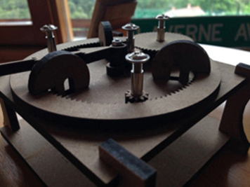
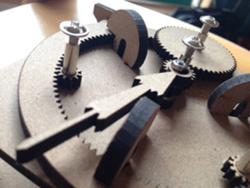
I chose a sheet of 5mm DM to cut out my gears, and the result is pretty amazing: the gears really engage smoothly with one-another.
The gears work fine with one-another, but I need to work on the assembly of the entire clock (adjusting the snap joints and finding the right screws.
That's all Folks.