Module 11 – Input Devices
Class
...
M.
In Class Tutorials
Not much of a tutorial really, just a lot of very helpful one-on-one sessions by Luciano. Thank you very much!

The Assignment
measure something: add a sensor to a microcontroller board that you've designed and read it- design a microcontroller board,
- add a sensor,
- read it
Well to make things easy (are you sensing irony here?), Luciano suggests that we make an pseudorduino with the microcontroler, and make a shield with the sensor to test and read.
Actually the idea is that whatever Arduino board we make can be re-used for the subsequent assignments. This is a good thing but we need to push a bit further our circuit design skills.
The idea
I would like to play with tilt and acceleration to see if I can learn something in order to make DooD self-balancing.
Looking up the fab lab inventory, I found a reference to the LSM303C by STMicroelectronics. Unfortunately this component is not available at this moment at Fab Lab BCN. Guillem pulled out a more basic 2-axis accelerometer they have in stock. It's a simple X-Y accelerometer MMA3201KEG by Freescale. This will do for my purpose at this stage, furthermore looking at the specs of the LSM303, it seems impossible to solder (it is extremely small, and the contacts do not protrude: you have to somehow manage to place solder underneath the chip).
So I'll do as Luciano suggested: first make an arduino board, and then I'll make shield for my accelerometer.
Making the ...duino
I chose to base my ...duino design on a mix of Luciano's Barduino and a Arduino schematic that I had Googled up. On that base, I decided to add:
- Standard Arduino ports layout (in order to be compatible with any arduino shield and so that any of the shield I develop for "...duino" will also plugin easily on a regular Arduino.)
- Mosfet transistors on 2 of the pins in order to drive natively device that require more power than what is provided by the ATMEGA. (with screw terminals for the power out pins)
- A USB port (just to get power from a computer)
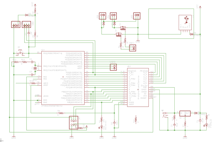
Making the schematic is never a major challenge, if you copy an existing one and guess arrange the extra stuff.
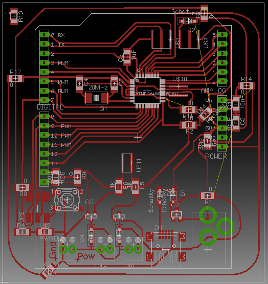
The real headache comes when you try to layout the paths and put everything on the board with the constraint you imposed yourself unknowingly.
My initial intention was to cram all paths and components within the boundaries of the shield headers, but as I progress I realise how complex it is to fit everything without crossing wires, and little by little my layout grew out of the headers' boundaries to make a massive 75mm x 75mm board: →
Despite all the help and advice i got in the lab, "...duino" never got off the ground. I did not manage yet to burn the bootloader...
...time goes by...
Weeks later I decided to move on and designed a brand new board I call the Mat2ino.
Making the Mat2ino
I got humble, removed some of my added features, and forgot I had ever seen the arduino schematic. So I'm just making a Barduino and I add a layout for Arduino shield compatibility. That should reduce the potential problem making.
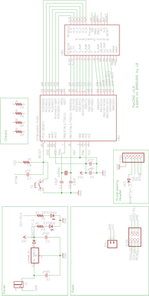

I can't exactly say it worked at the first time but minimum trouble shooting and debugging got the hoped for response from the board, and Bootloader got burnt smoothly, and I got my pin13 led to blink in a flash (or should I say to flash in a blink?).
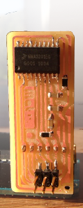
The Accelerometer Shield
The MMA3201KEG is straight forward. Despite boasting 20 physical pins on the chip, only 8 are actually connected and four provide data as a feedback:
- ST - Self Test (Not used here)
- Status
- X-OUT - provide X-axis acceleration data
- Y-OUT - provide Y-axis acceleration data
and the chip simply requires VCC and ground. So all-in-all I can make a shield with 6 pins to connect to my "Arduino" board. I pu two headers for more versatility, but 6 in-line pin header is very convenient because it's ready to be plugged into an arduino board. when pluggeg in to the arduino, I need to make that the port taht is connected to the "VCC" of my shield is [ HIGH ], and that which is connected to the "ground" of the shield should be forced to a permanent [ LOW ].
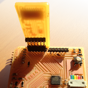
I'm pretty happy whith this shield system which is pretty convenient.
I tested the shield and it gives some satisfactory results although I'm not too sure how to calibrate it based on the data I get in order to have a higher degree of precision.
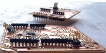
The working board can be seen in the module: "interface and application programming".