Module 04
Computer-Controlled Cutting
Now we’re starting to have hands on experience with the machines that make.
Class
Neil explained the principles cutting machines and detailed a little more the vinyl cutter and the laser cutter, going over what material can be used on these machines, recommendations etc...
Demo and explanation of the machines
On Friday, Luciano in FabLab Barcelona showed us in details how to set either of the two laser cutter they have on site.
The small one (the Epilog mini 24) is pretty straight forward as operating it resembles sending a file to a printer with not much fiddling around to get the material and laser head in place. The larger one is more industrial: it’s very large and relies on a human print driver.
Home Learning - Getting to fiddle with “parametrics”
Now that I've spent most of last week trying to figure out which software to use to do 3D graphics and then figuring out the rudiments o designing with it, I need to find the software to make parametric designs
Grasshopper
A major pressure is put on me to learn and use ‘Grasshopper’:
- it’s Rhino’s sidekick
- it’s extremely thoroughly documented with plenty of tutorials online.
- Instructors at Barcelona use it and can be very helpful to solve problems and facilitate the learning process.
There is one glitch however: [IT DOES NOT RUN ON A MAC]… Solution I need to set up a double boot in order to run windows on my laptop.
Given the small amount of disk space left on my Mac, I decide to go shop for another solution.
InkScape
Inventor Studio
Kokopeli
OpenSCAD
I ended up checking out “OpenSCAD”, which is free, light and runs on iOS. This met some of my requisites. No fuss about installing: once downloaded you move the program to wherever you think is good… (“program directory” for example).
When you open the program it is not clear what you can do: there is literally no GUI. Just, for each document you open, a window on the right where you enter your lines of code, and on the right-hand side a window where you can see the three axes XYZ, and where you can visualize the result of the code you typed.
Now what exactly should I type on the left?
In the help menu you can click on “OpenSCAD Homepage” or “Documentation” They both take you to the OpenSCAD website, although the latter goes straight to the documentation page.
I found the documentation quite clear, but was eager to get down to business after having looked at 4 different options. So I typed 3 or 4 basic commands to see the results, and then try to guess some more: “hexagon” is not an existing command…
To try and save time, I googled “parametric hexagon OpenSCAD” and found a few interesting links [the Makerbot website has some tutorials]. Eventually I found what I was looking for on “thingiverse”: there was an object that contained hexagons, so I downloaded and reverse engineered to find the command I was looking for: “circle” is the actual command (setting the iterations to 6 will give you an hexagon).
With that example I could write the code for the basic element of my construction, and I was surprised how quickly I got my result, and was equally happy to realize that it was done with very few lines…
The Assignment
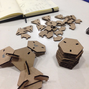
design, make, and document a press-fit construction kit
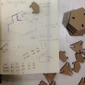
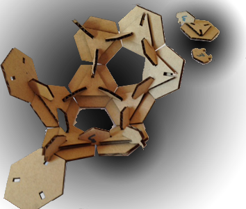
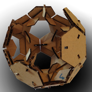
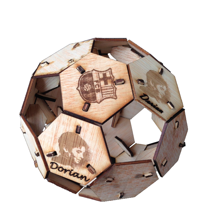
With the time I spent trying to find the software that would suit my needs, I found myself with little time left to work on an idea for the assignment. My original idea was to make octagons slit in the middle of each side in order to have it coupled with another one. The idea was to make a construction set with the size from center to inner edge of groove vary in sizes (10, 20, 30, 50, and 80mm).  But I could not think of a joint different from that shown in class by Neil, so I set for a different project: a soccer ball. This, I thought, might even earn me the admiration of my sons. As I am writing these lines they are watching Barça beating Manchester City.
digitizing the model
As seen above, by the time I had decided on which software to use I already had my basic shape: the hexagon, and it was parametric. 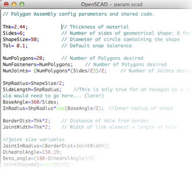 I put all the parameters in a separate file so that I could call the same file when working on the joint element.
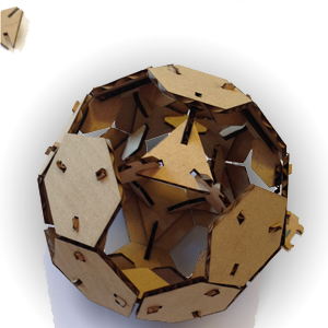
Designing the joint was more complicated. I needed to determine the adequate angle for my pieces to fit together. I struggled for a bit trying to figure it out on my own and eventually looked it up on the web. I learnt that it’s called the dihedral angle, and that the value for the geometric shape I’m building (a truncated icosahedron) is: 138.19.
Downloadables
[ download MASTER file: "MultiShapes_fastenr.scad" ]
[ download PARAMETERS file: "param.scad" ]
[ download HEXAGON file: "RegularPolygon.scad" ]
[ download JOINT file: "PolygonJoint_v3.scad" ]
[ download FASTENER file: "Fastener.scad" ]
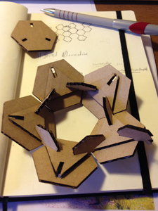
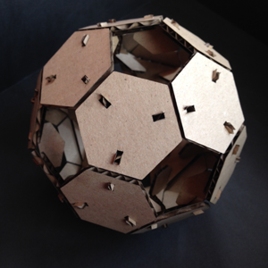
The fastener is placed on the in-side of the hexagons to make a firmer assembly. It is not necessary, but I recommend putting it if you want to toss the ball. The fastener also facilate the assembly of the first few pieces which otherwise tend to not hold well (see assembly below ▼ ).
output to laser cutter