Module 05 -- Electronics Production
Class
hmmmm... Milling and soldering techniques
In Class Tutorial
Milling the board
Here in Barcelona we have it easy compared to other students around the world: we have a set-up that is proven and that runs using the fab modules, and we really do not have to worry about initial settings and testing.
We'll pay for that down the road the day we actually need to set up a new machine and try the proper tools and tips… But for now, it looks as though if we follow the step-by-step recipe and are extra cautious with handling the drill bits we can’t go wrong. So I'll just write down said recipe here:
Before you get started you need to have your board layout designs downloaded and at hand. These are two SVG graphics –one for the engraving that will etch out the copper from the surface of the virgin board and the other design is a contour and will be used to trim the board to the final size. First we etch the circuit, and then we cut (using a different drill bit). I will do a step-by-step guide of the etching part and then you can pretty much go through the process again after having changed the bit and adjusted the settings for cutting rather than etching.
On the computer that is hooked to the milling machine and on which the fab module is installed:
- tasks performed on the computer ▼
- tasks performed on the milling machine ▼
- launch terminal
- type: ”fab” ► this will launch the Fab GUI.(Some changes have occurred and we should launch a different version of the Fab mocule using: [“sudo fab?”])
- In the fab GUI select the image format of your design (ex .PNG) and select the process “Roland Modela (.rml)” .
- Click on ”Make_PNG_RML” button.
- select the tool on top of interface → for etching ["mill trace (1/64)"] for cutting: ["cut out board (1/32)"]
- All presets should be correct : “type”=[3D plane] default value for "offset to fill" is [4]
- If you're not too confident about your soldering skills change "Offset to fill" value to [6]; setting it to [-1] will etch out all of the excess copper.
- Make sure the tool bit on the milling machine is the proper one, if not replace it by untightening the spindle using the hex key wrench two screws need to be loosened. ⚠ [retain very carefully the bit as to keep it from dropping onto the plate: the bit would most certainly break]
- press [view] button in order to home the x and y of drill head.
- Key in the x and y origin of your board on the GUI and press [move to Xmin Ymin] this is guess work and could require a few iterations.
- Loosen the bit in the spindle using the hex key wrench (carefully retaining it so that it does not drop) and gently lower it onto the copper plate. Tighten the spindle
- Press [make RML]
- press [send it] –make sure you did the [make RML] before sending otherwise you’ll end up sending the file that was previously loaded in the RIP of the milling machine.
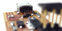
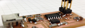
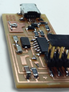
Staffing the circuit board
this activity does not challenge your intellectual abilities as much as it does your physical fitness. In addition to the list of components, I recommend you be armed with:
- Excellent eyes - preferably 20+/20+ vision
- cool hands - avoid excess caffeine
- patience
Nowadays, we’re happy to know that we can choose between two different technologies for mounting components on circuit boards:
- THT – Through Hole Technology.
- SMT – Surface Mount Technology
The latter presents numerous advantages in particular for robotized staffing of boards. Wikipedia lists a few disadvantages amongst which I’d like to quote the first one:
«Manual prototype assembly or component-level repair is more difficult and requires skilled operators and more expensive tools, due to the small sizes and lead spacings of many SMDs.»
strong of that knowledge we can listen to the instructions and recommendations. First thing we’ll need to know: we’ll be working with SMD devices…
Basic recommendations include:
- Set the temperature of the iron between 300ºC and 350ºC –when you’ll get better you’ll go faster and you can make that temperature slightly higher.
- Start from the center then out–like when lighting the candles on a cake.
- Start with smaller more complicate components.
- Some components like diodes or ICs are “directional”, so pay attention to the markings in order to not place it in the wrong direction. –with my eyes I pretty much needed a microscope in order to see the line indicating the cathode on the diodes we used
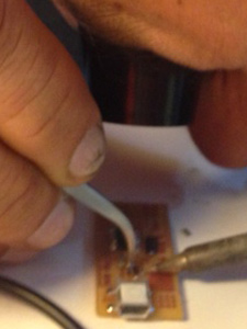
- put extra solder on the parts that will be submitted to mechanical stress such as ports or headers.
- Use the solder braid to unsolder –I personally found that quite tricky
- [ed.: try not to loose your finished work…]
Testing and uploading the program
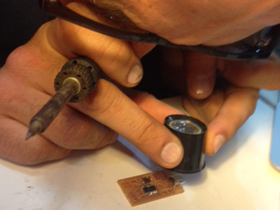
I didn’t pay enough attention to Luciano’s instructions as I was busy staffing a second circuit as could not put my hands on the one I had done on Friday.
The good news is I did go much faster the second time around partly thanks to the experience, and partly thanks to the magnifier lamp Luciano has bought for the lab; its much more comfortable.
As I did have some catching up to do after missing Luciano’s tips and pointers, I went to the extremely thorough tutorial page, and proceeded to check-out…
The Assignment
Set your brain to rest, and muster your nerves for this is not an intellectual challenge but requires a certain Zen attitude. No thinking required, just build an ISP [In-System Programmer] → mill the board, stuff it with components and program it.