Modules 17 – applications and implications
Class
Where we got to see a variety of really cool projects that came to life during prior sessions of Fab Academy...

The Assignment
plan and document a final project that integrates the range of units covered:
- what will it do?
- who's done what beforehand?
- what materials and components will be required?
- where will they come from?
- how much will it cost?
- what parts and systems will be made?
- what processes will be used?
- what tasks need to be completed?
- what questions need to be answered?
- what is the schedule?
- how will it be evaluated?
projects can be separate or joint, but need to show individual mastery of all of the skills where possible, you should make rather than buy the parts of your project
.
what will it do?
DooD is a doodlebot: an autonomous drawbot propelled by two wheels that moved by stepper motors. It will follow sets of instructions to reproduce on horizontal planar surface a particular design.
It will understand a specific set of instructions and have a few proprietary fonts, but should understand and interpret standard languages such as HPGL or G-code. Ultimately it would be grate to be able to understand some PostScript --but that will have to wait.
who's done what beforehand?
There are many drawbots that have been made. You can class them in two different categories:
- The ones that work within a frame or fixed perimeter.
- The ones that can wander around with no boundaries (these I call autonomous).
Framed Drawbots
There is an example of the "framed" version on the Fab academy tutorial site.
Autonomous Drawbots
I shall add here links to different autonomous Drawbot projects, but I must mention the one which could be considered the grandfather of all Drawbots is the Turtle, born based o the works of MIT mathematician and Educator Seymour Papert. The turtle along with my daughter's ideas formed part of the original inspiration for the project.
what materials and components will be required?
Please refer the Bill of Materials for detailed list of purchased materials.
Laser Cut Components
The body should be made of a sheet of laser cut rigid material 4mm to 5mm in thickness, I tried two different materials one was 5mm thick MDF (Medium-density fiberboard) and another frame I made out of clear acrylic glass.
Both materials worked fine but I decided for the transparent aesthetic. There are issues with the rigidity and the snap joint tend to break (design of these needs to be improved).
I also laser cut the wheels out of this material, and was planning to use noodle-flat rubber bands as tires. I had two issues with these one was the tires I did not actually test these tires, but I was afraid they would come off to easily. The other issue is the attachment to the motor axis. It's not easy to find the size of hole to cut to have the right tolerance, and it's not simple to incorporate a tightening mechanism so I'll try to 3D print wheels.
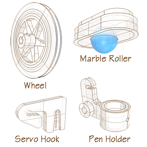
3D Printed Elements
- The wheels
- The pen holder and lever
- The pen lift hook
- The marble cradle (used as omni-direction wheel)
- The servo motor cradle
Hardware supplies
The motors I used in this version have threaded screw holes that accept M3 screws. This size screws suits me for all my screwing needs on that project, so I purchased a M3 tap and a handle for where I need to fasten or tighten. I found that this 20 € investment [was a pretty interesting tool for the needs of this project.
Here is the basic list of small hardware supply:
- 2 x 60mm by 3mm O-rings for the tires (needs improvement)
- M3 metric screws and washers and nuts (20 screws nylon and iron, 12 washers, 6 nuts)
- 91mm plastic rod. I used a plastic rod that is made for the manufacture of scale models that I had purchased previously at an insane price. Basically it's a 4mm diameter hollow lollypop stick.
- a marble (15mm diameter) -- the most convenient place to look for it should be your son's bedroom
- a pen whose diameter should not exceed 12mm
Electronics supplies
All small electronics components are part of the FabLab inventory (except for some headers I purchased separately).
The main circuit boards and all "shields" can be milled within a 120mm x 60mm single sided copper board. All boards are milled on the Modela using the FabModules.
Here is a summary of the components required (for a complete list please look-up the BOM).
- Processor: ATMEGA 328
- 16Mhz crystal
- 5V. voltage regulator.
- Diodes
- 2 LEDs
- Resistors and capacitors
- Jack for power
- Assorted connectors and headers
- jumper wires
- 4 H-bridges for motors drivers
- Accelerometer shield (various solutions need to be tested)
- Battery charging circuit (under investigation)

Below is a list of the larger components:
- Motors: Stepper Motor: Bipolar, 200 Steps/Rev, 35×28mm, 10V, 0.5 A/Phase
- Pen Lift Servo motor: Tower Pro Micro Servo 9g SG90
- Board battery: standard 9V. battery
- Motors Batteries: 3x 3.7V. Lithium-Polymer 555462 2000mAH mounted in series. (borrowed from Smart citizen boards)
where will they come from?
Please refer the BOM for details.
how much will it cost?
Please refer the BOM for details.
what parts and systems will be made?
The plan is to make all the parts that can be made in a FabLab. Some basic hardware and small Electronic components will be sourced from the fab inventory for the main part. The larger components were sourced from Electan.com an electronics supplier in Spain.
what processes will be used?
- Body is laser-cut.
- Mechanical parts are 3D printed.
- The circuit board are designed in Eagle, reworked in Photoshop, then milled on the Modela.
what tasks need to be completed?
Please refer the result page of the final project to see the state of the art of the development of DooD.
what questions need to be answered?
- what is the most appropriate sensor for self-balancing, accelerometer, inclination sensor, etc...?
- How to make sure the wobble of the self-balancing DooD will not affect too much the drawn figure?
- How to manage the Pen-up/Pen-down mechanism making the state change firm and precise while maintaining flexibility when the pen is down?
what is the schedule?
how will it be evaluated?
There is a long way to get DooD to understand and reproduce any HPGL file or even to understand G-code or Logo. But I can start by first evaluating the accuracy of basic commands such as:
- Draw a straight line.
- Draw a geometric shape.
- Draw a regular curve.
- Move to relative position X-Y.
- Orient DooD in a specified Direction (depending on which accelerometer chip I chose to use, DooD may or may not be equipped with a compass, so the logic is to assume that it is not). DooD understands as his "north" his orientation at the start of the execution of the program.
That's all Folks.