This week's fun assignment was:
Mechanical design
Group assignment:- Design a machine that includes mechanism + actuation + automation + application
- Build the mechanical parts and operate it manually.
- Document the group project
- Document your individual contribution.
Mechanical design & machine design
What I did this week
Group assignment
This week the group assignment is documented on separate page that can be found here: Group assignment page: Mechanical design & machine design
Individual assignment
This was the most fun week in Fab Academy until now, but also the most labor-intensive.
One of my first ideas for the final project was a T-shirt drawing machine. I didn't keep the idea going for a very long time but in the back of my mind I knew I was going to build one after Fab Academy.
As fate would have it, I ended up building one in Fab Academy.
Me and Pablo from Deusto Lab, were partnered up by our instructors and we tried to divide the tasks as fairly and evenly as possible/p>
My tasks:
- Studying various CoreXY machines and come up with one that we could build;
- Procuring parts (stepper motors, smooth rods, CNC Shield, etc);
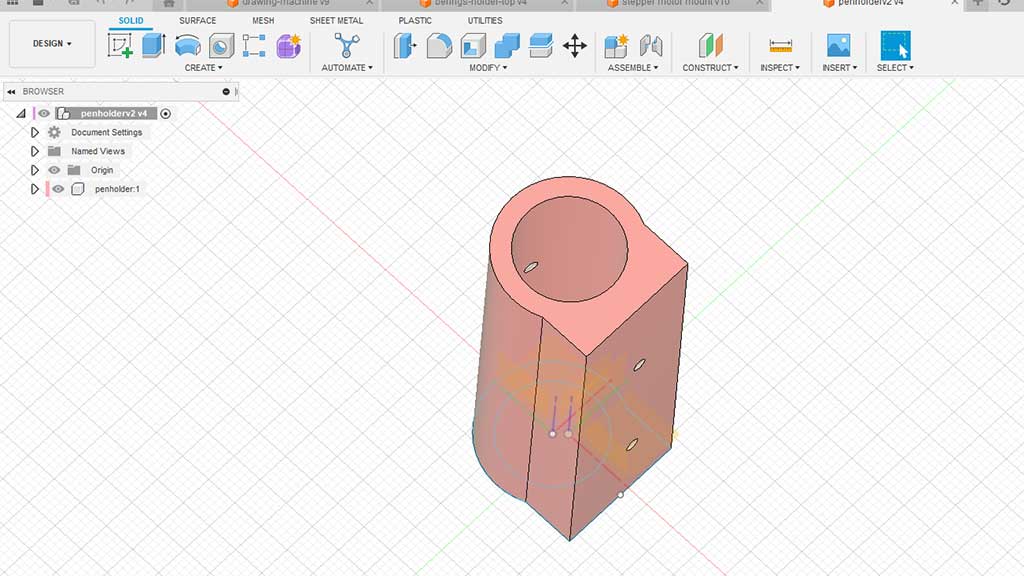
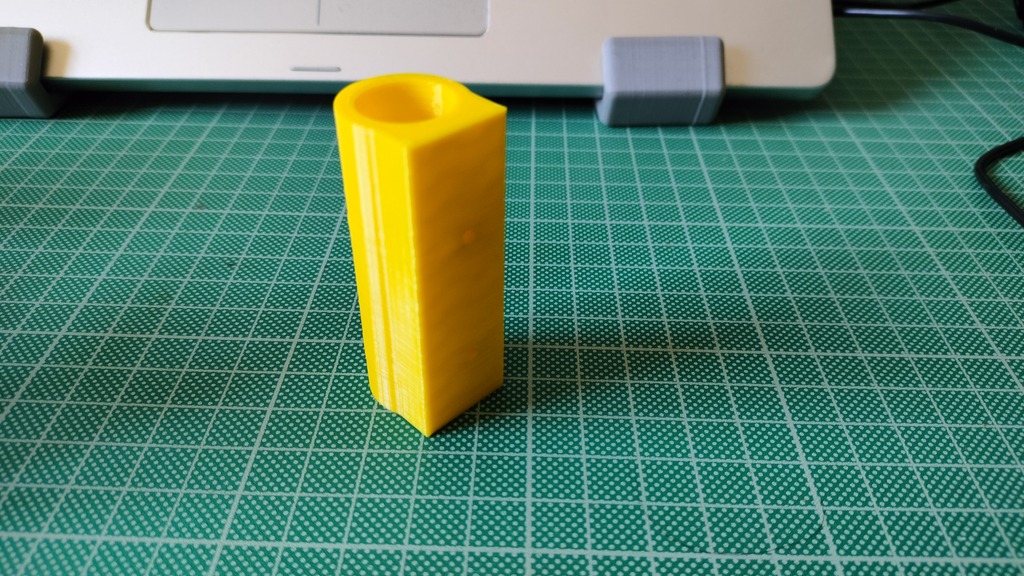
- Design 3D Pen holder with servo mount and bracket;
- Design Servo pen lifter;
- Software process from creating image to sending to machine;
- Software process to control the machine;
- Parts fabrication: 3D printing all parts;
- 3D Modeling of the entire machine and animations;
As Pablo Badiola would only meet me in Fab Lab León for a Weekend, it's only natural that I got these tasks.
Studying various CoreXY machines and come up with one that we could build;
I started by making a list of links to CoreXY machines and studying each of the links:
I settled for the most simpel design the MaxDraw. But it would have to be 3D printed.
Eventually I found a couple of designs in Instructables and decided I would mix them up.
- A pen plotter design
- Poetry for Python
- Another Pen Plotter from former Fab Academy students
- Another Pen Plotter Design
- And another Pen Plotter Design
- One more Pen Plotter Design
- Another Pen Plotter Design with AI
Procuring parts (stepper motors, smooth rods, CNC Shield, etc);
I made a bill of materials that had to be sourced based on other projects that I found online and tried to keep these materials down to what I already had at home.
Here is the bill of materials:
- 1 x Arduino UNO;
- 1 x CNC Shield;
- 2 x A4988 Drivers;
- 2 x NEMA 17 Stepper Motors (40mm);
- 2 x End stops;
- 2x 20-tooth GT2 pulleys;
- 1x GT2 Timing Belt (1.4 - 2 meters);
- 1 x micro servo SG90 with a long cable;
- 2 x end stops sensor;
- 1x A power supply capable enough to use the motors without fret;
- 1x USB cable;
- 4 x 8mm smooth rods;
- 2x M10 threaded rods (400mm);
- 8x M10 nuts;
- 8x 30mm M3 screws with nuts;
- 8x 6mm M3 screws;
- 2x 15mm M3 screws;
- 4x 16mm M3 screws with nuts;
- 4x M3 washers;
- 2x 4mm OD, 100mm tubes;
- 8x LM8UU Bearings
- 8 x 623EE Deep groove ball bearings;
- 1 spring;
It was a bit of a challenge to procure some parts, but I managed to find everything we needed by cannibalizing an old Geeetch 3D printer that I'm not using anymore.
The old printer uses a custom board to control the motors, but I did have an Arduino CNC Shield from another project lying around.
I name the old printer Celine in honor of Celine Dion as it was very loud. It's only fitting that I made a meme...
It's looking pretty easy right? Well, look again as the old printer didn't have enough bearings!
My first thought of course was to buy them, but as it's saturday there is no way to get them, even if I ordered them online they wouldn't be delivered during the weekend. I like to support the local economy and in this case, in my hometown, I set out to find a bearings shop.
I found one called "House Bearings" (Casa Rolamentos). Of course, closed during the weekend so no luck on getting bearings for the weekend...but what If I printed them?
And that's exactly what I did!
First I designed what I thought would work as a bearing but soon after decided to just look online and see if anyone tried to print bearings, and a lot of people did.
After printing the bearings, they need to be sanded down and lubricated.
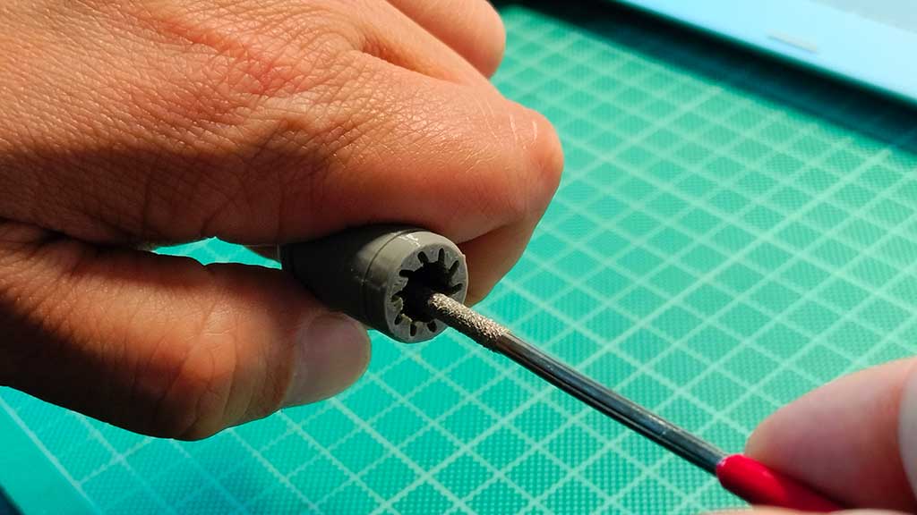
Here is the final result:
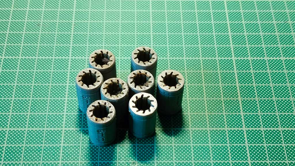
Do they work?
They do, but I decided to order some online anyway. But the plastic ones will do for a first test build of the machine.
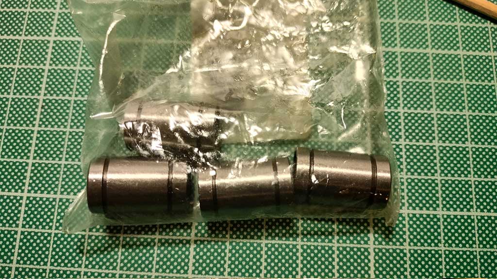
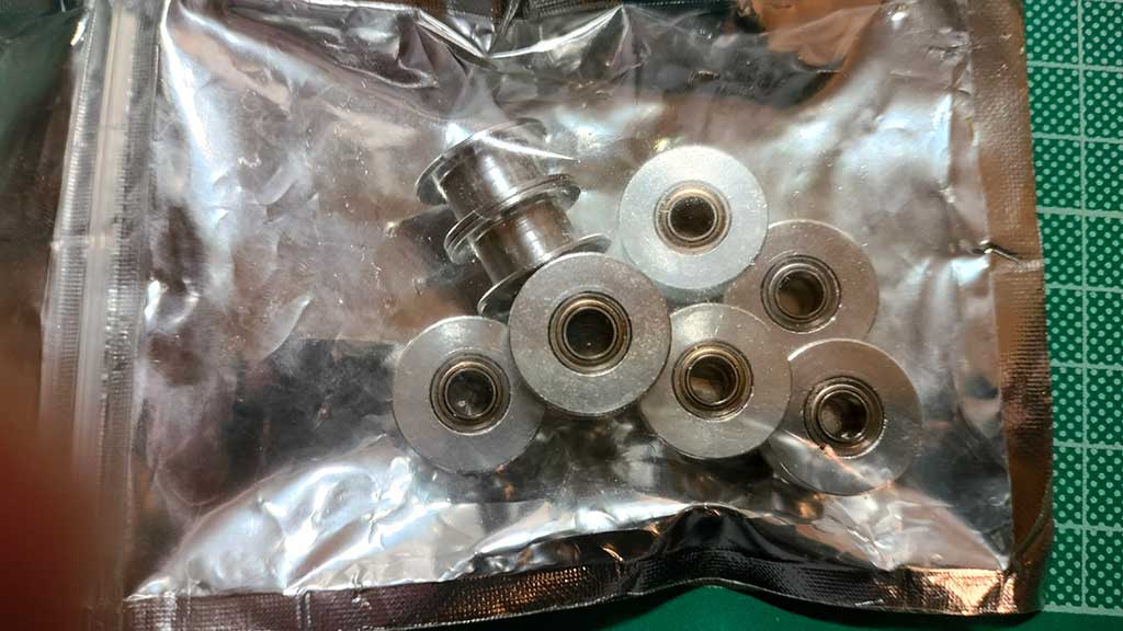
I also didn't have the 623EE ball bearings nor the F682ZZ ball bearings. This last bearing type is usually recommended on a lot of instructions for building machines like the one we are going to try and build.
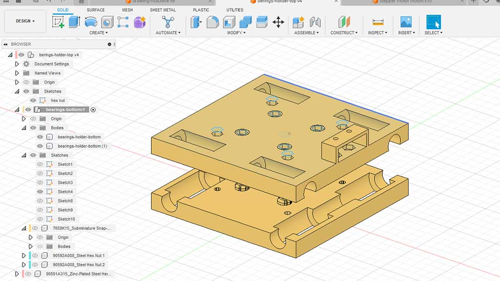
I decided we would be using the 623EE bearings but I would model and print a simple polly for the bearings. I ordered the bearings online as locally I could get them but they were very expensive.
These bearings are used as the timing belt guides.
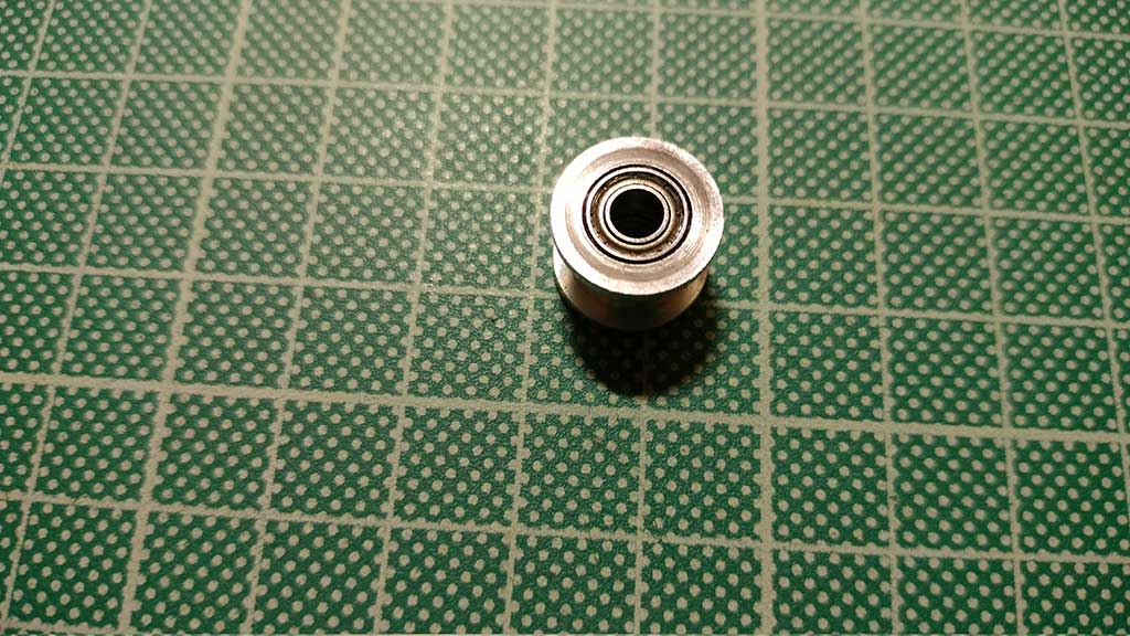
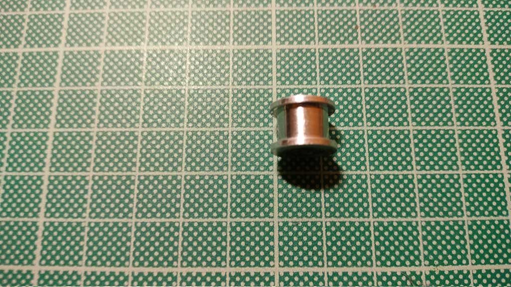
But I just need the bearings as I have design and printed a polly:
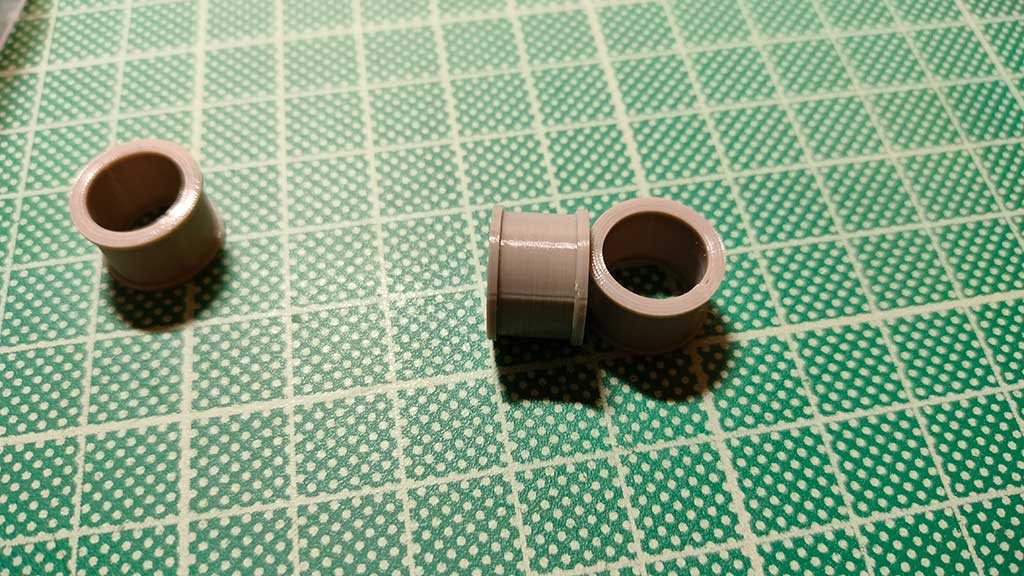
I also ordered bearings already with the polly but ended up not using them as mine fit the design better.
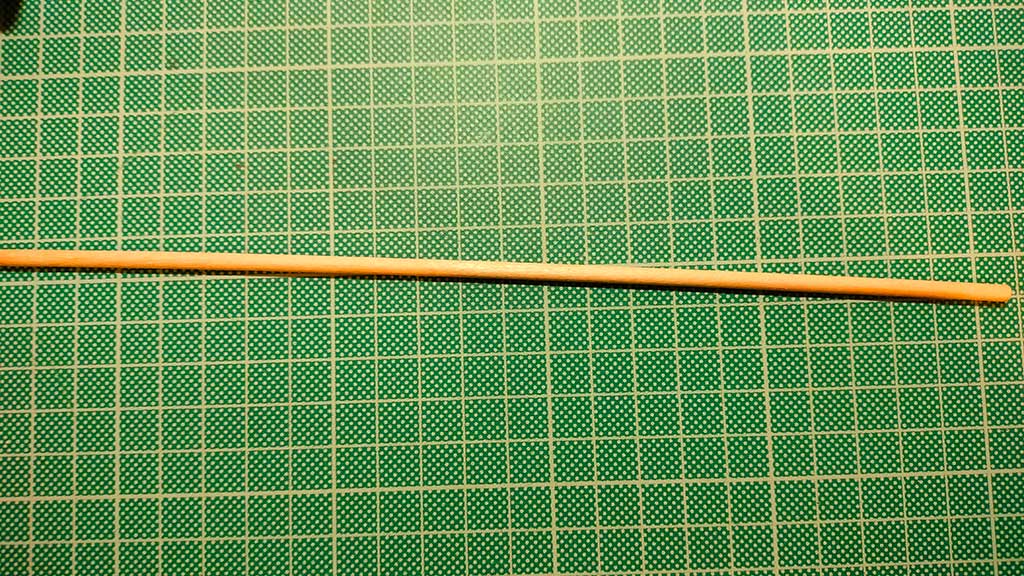
Another part that I could not find were the tubes to be fixed in the servo motor part but still allow the pen carriage to slide.
I decided to try and use for the first build a cutted barbecue wood stick. It doesn't have 4mm but 3.8mm. I will just design the part for this dimension.
Aside from procuring parts I also tested the electronics to make sure that everything was in good working condition.
I connected 4 stepper motors (although we were only going to use 2 for the machine) to the CNC shield and using Universal Gcode sender tried to move the stepper motors.
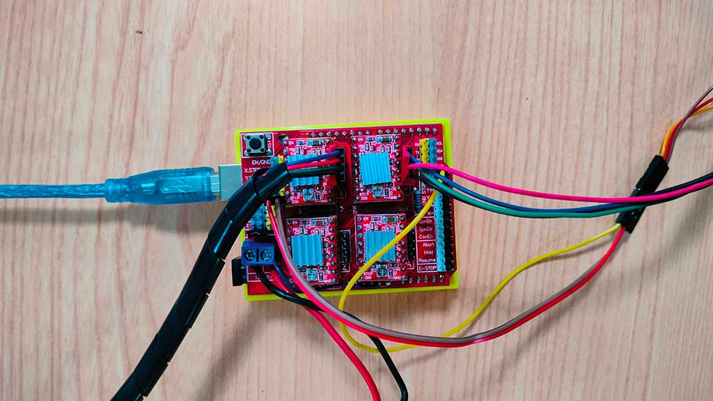
Only 3 of the motors moved. I checked the wiring and everything was correct. Upon inspecting the board I found a short!
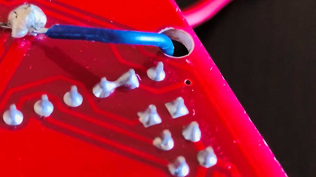
Tested with the multimeter to make sure and the beeping from continuity proved that there was a short!
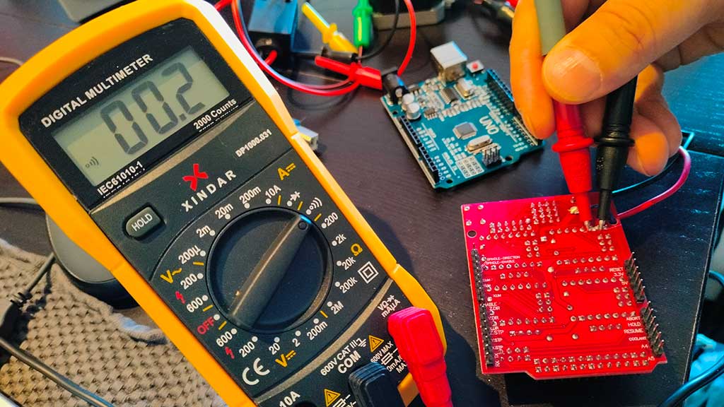
I cut the connection between those two points and everything started working as it should.
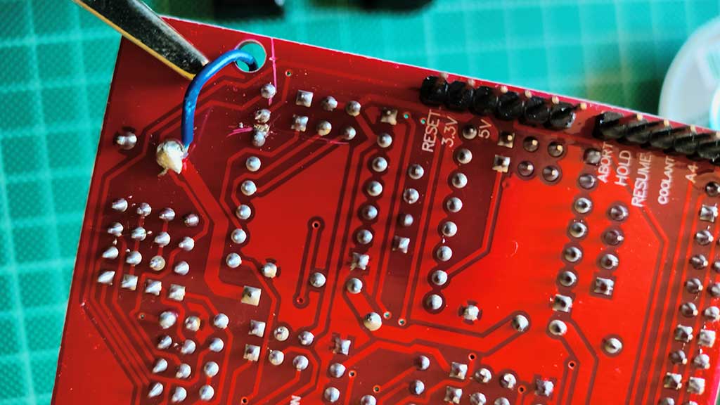
I also soldered the blue wire between Vin and + Header to power the arduino from an external power source or power the shield and motors from the Arduino.
As we can see from the image, the Bench Power supply indicates that the 4 motors need +-1.62A. I found that the correct value is 1.72A. Also the voltage here is at 7.2v.
The Power supply
One of the most (and some will say the most) important part of the machine is the power supply.
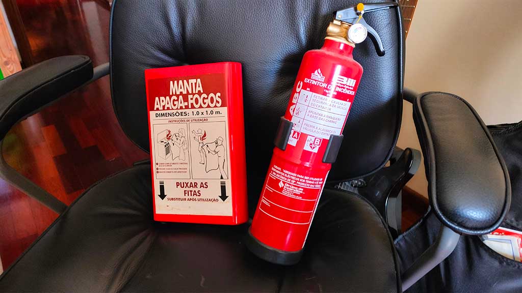
For testing I used a Bench Power Supply of a chinese brand. BAKU!
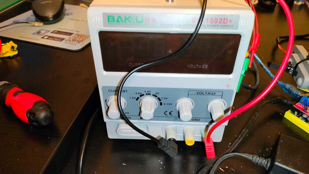
But truth be told I never trusted it, so I kept a Fire blanket and a fire extinguisher on hand.
Better safe than sorry!
Not long after writing this I started sensing the smell of melted plastic coming from the power supply:
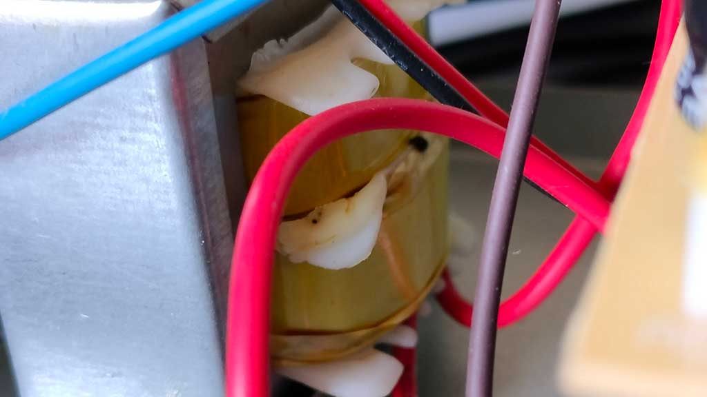
It started to melt and give out irregular power.
I'll just bench it! (pun intended)
I dived into the "someday this is going to be useful" bin to find a power supply that would fit the power needed for the machine.
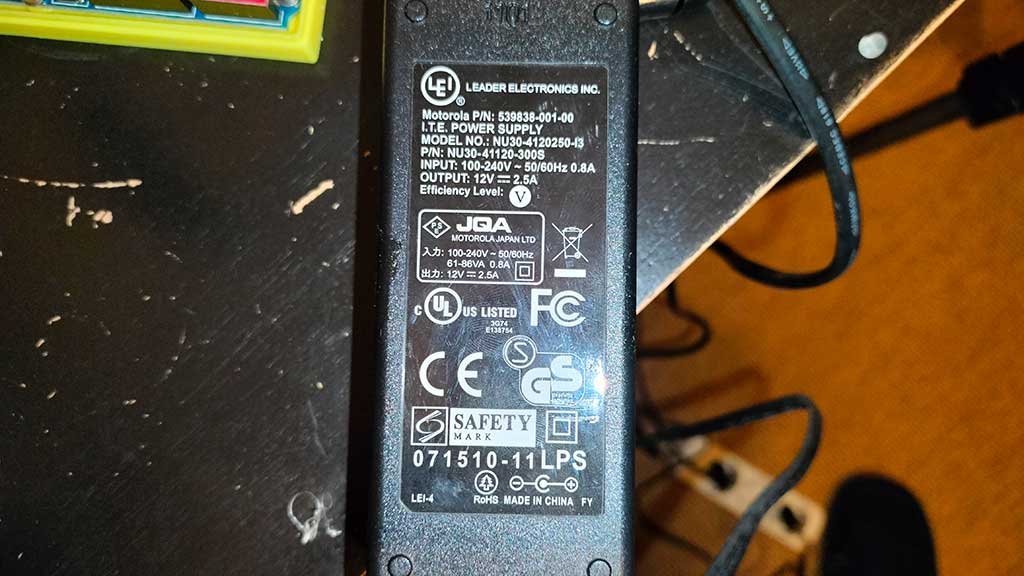
Our bench one already told us that it would be a 12V 1 to 2A one.
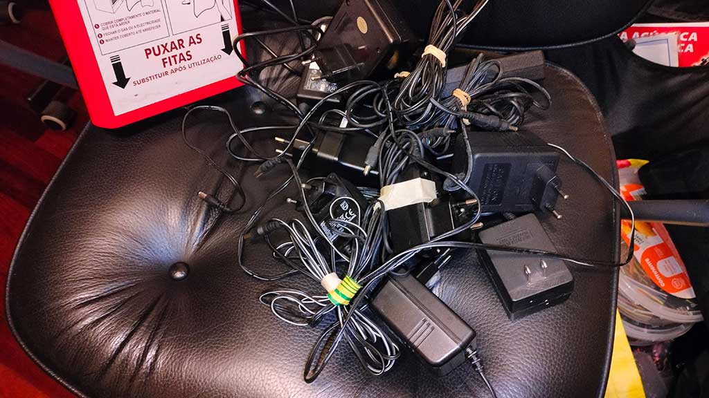
And found just the right fit. Not sure what it was originally from, but it's from a Motorola something.
Software process from creating images to sending to machine + Software process to control the machine;
Before diving into the software needed to make the machine draw something we must burn it into the arduino the GRBL library.
GRBL is a "An open source, embedded, high performance g-code-parser and CNC milling controller written in optimized C that will run on a straight Arduino" and although it can be seen as outdated, the truth is that it works!
I downloaded the latest release from GitHub (link in the links section) and installed it.
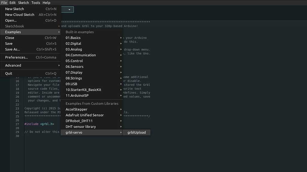
After installation I just needed to go to the File > Examples menu and select the GRBL Upload example and upload it to the Arduino.
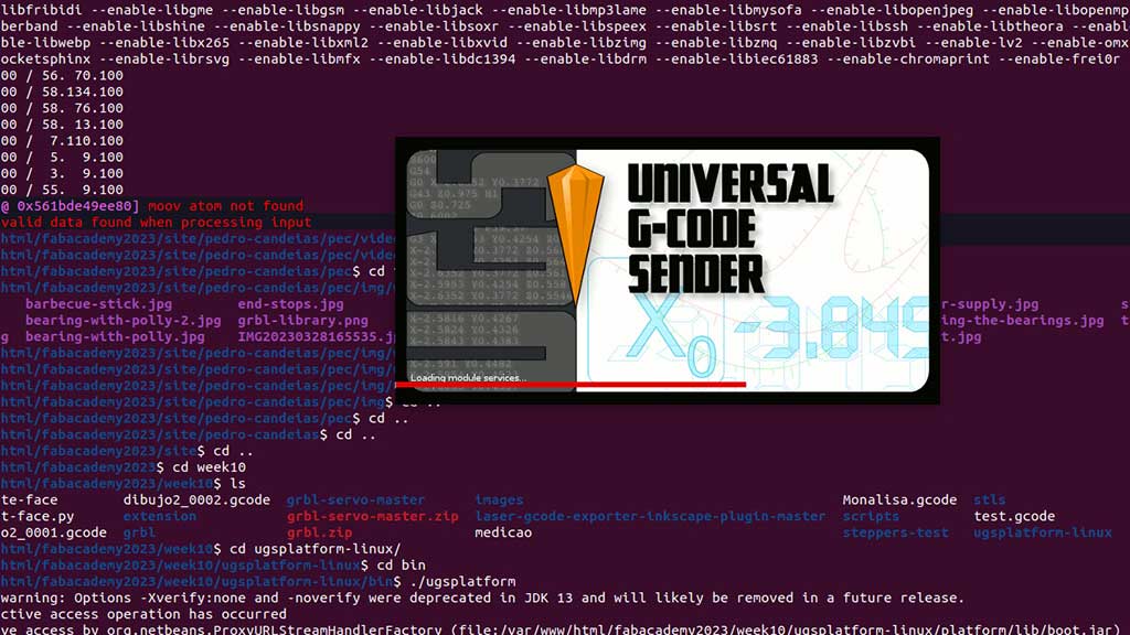
Now we need a way to control the motors and servo. For that we are going to use the Universal Gcode Sender.
A cool thing about UGS is that it runs on pretty much any popular computer OS and works with pretty much any controller.
Universal GCode Sender is a freeCNC controller software package. The “Universal” designation means that it will work with a lot of the firmware options around, such as G2core, TinyG, and GRBL.
I downloaded it also from GitHub and extracted the tar.gz.
Inside the folder there is a bin folder and inside that folder there is a ugsplatform file.
Via terminal, in the bin folder, type ./ugsplatform, that's it.
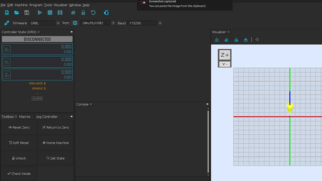
Now we can access the firmware settings by typing $$ in the text box on the bottom of the
interface.
I checked the parameters $100 and $101. These parameters define how many steps
are required for the machine to go 1mm.
The Nema17 we are using is a 200 steps motor, and the GT2 timing belt is a 2mm pitch, so I found online
that the value for $100 and $101 should be 80.
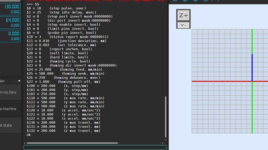
As we can see from the prompt the values are very different, so we need to adjust them.
I will later measure the distance the machine travels for 100mm and make the necessary adjustments but for now, 80 will be the value.
To introduce a new value we just need to write in the terminal $100=80 and
$101=80
Creating GCode considering the servo
There are a lot of ways to create Gcode. I can use inkscape, Prusa Slicer, Tinkercad and.. Python!
The challenge here is that we are using a Servo to push the pen Down or pull UP.
Instead of a Laser, we will use a servo and the Gcode must include the M3 S255 to push the
pen Down and M5 to pull it up.
As this machine is intended for line drawing I set out to find a SVG to Gcode compiler in Python and Lo and behold.. I found a lot of them.
I picked one and tried it and everything seemed to work fine, except ... the Pen was pushed DOWN where it should be pulled UP.
I just hacked the generate.py script to invert the order of the commands and also to make the script write Gcode to a file instead of just printing it.
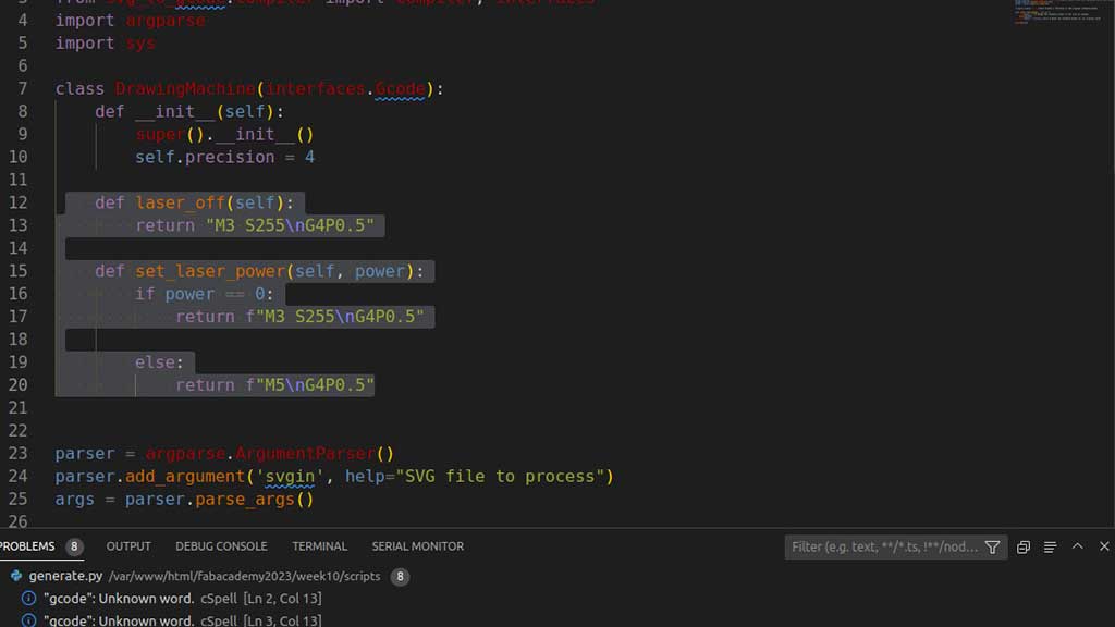
Now I just need to write in the terminal python3 generate.py name-of-the-svg-file.svg and
script generates a Gcode file that I can use in Universal Gcode Sender.
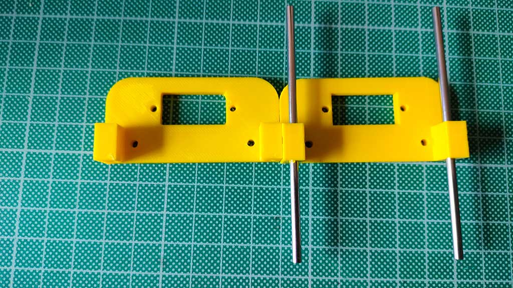
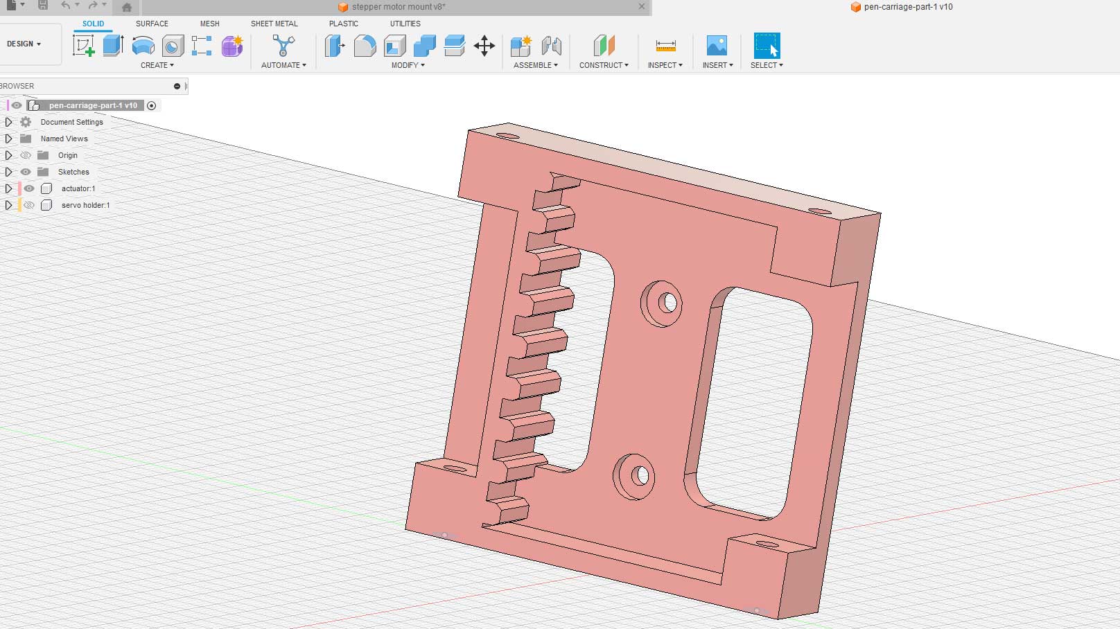
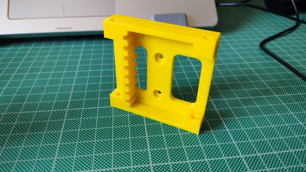
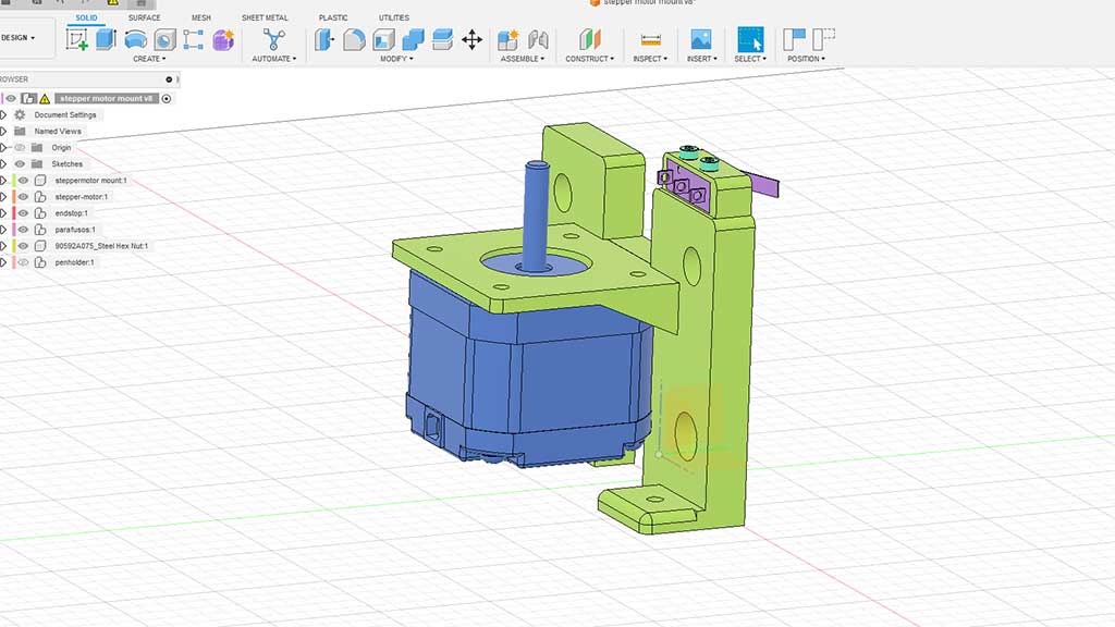
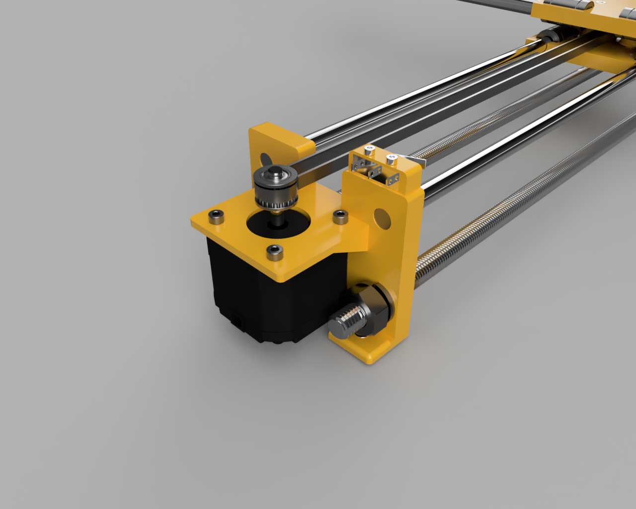
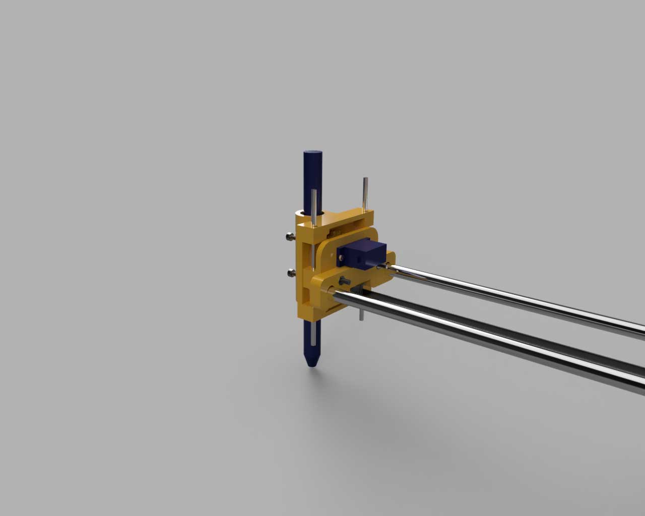
Design 3D Parts: Pen holder with servo mount and bracket + Servo pen lifter + Parts fabrication;
A lot of pen plotters use a way of pushing the pen up and down that I don't really like as they usually assume the pen is sideways or in a diagonal
I would prefer if the pen is vertical, so I tried to design a pen carriage with a gear.
The 3D models were done in Fusion 3D and the files are in the Files section:
I did a lot tests and designs before getting to a final part:
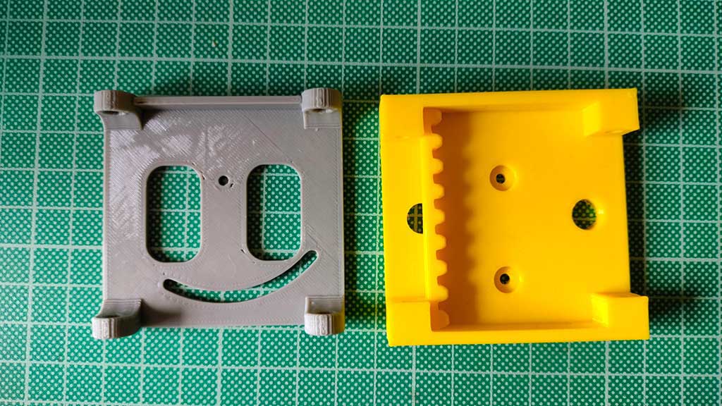
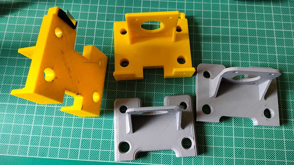
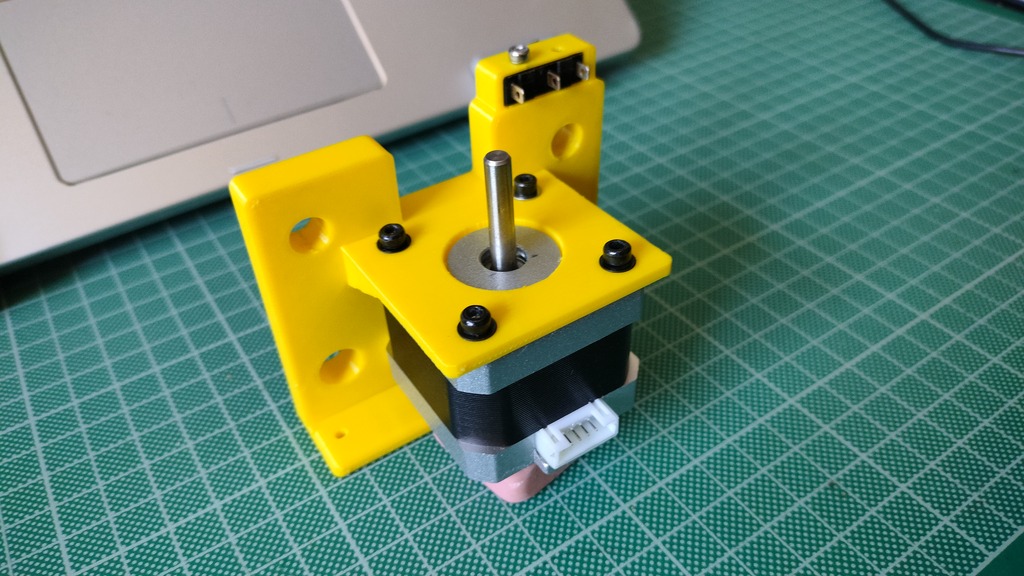
The first version of the machine was built with some of this parts.
These are some of the parts in the final version:
3D Modeling of the entire machine and animations;
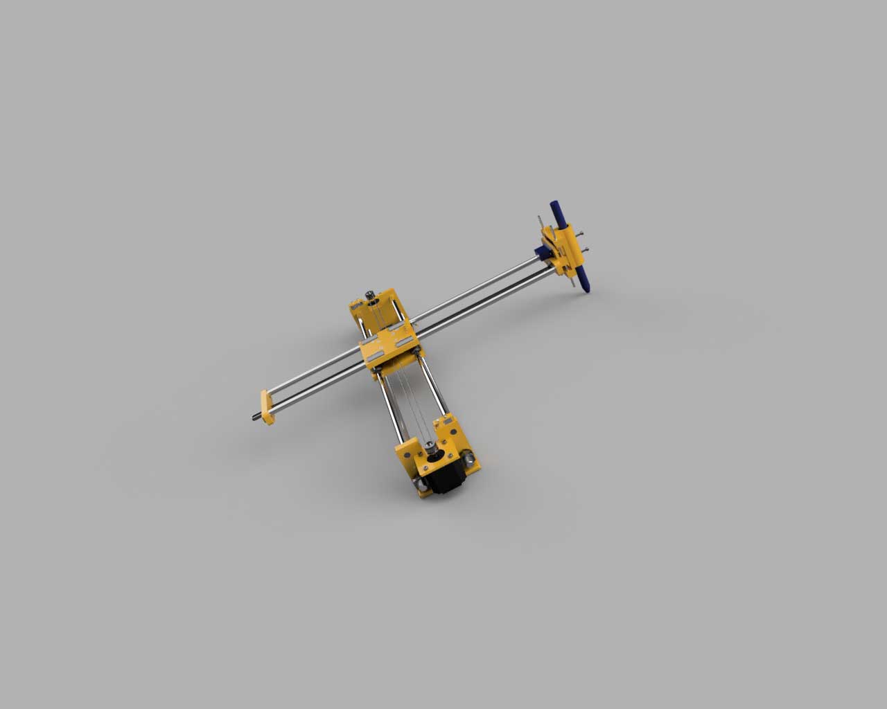

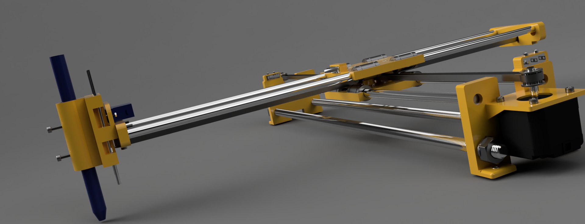
An animation explaining the build process.
For the final project
Nothing was done for the final project this week.
Files
Learned this week (in no special order)
- Don't trust a shady power supply;
- Order parts with enough time to not have to improvise;
- More Python!
- The names of screws and bolts in english;
- How difficult it can be to source some parts!
Notes and Thoughts
A Core XY machine is a great machine design has it as so much potential!
From one basic machine we can build a sand drawing machine, chess playing machine, CNC machine, drawing machine and so much more.
Links
- GRBL;
- 623EE Deep grove ball bearings;
- LM8UU Linear Bearings
- Raspberry Pi Camera 2 Documentation
- Python script for linedrawing
- Python script for linedrawing
- Python script for linedrawing
- A pen plotter design
- Poetry for Python
- Another Pen Plotter from former Fab Academy students
- Another Pen Plotter Design
- And another Pen Plotter Design
- One more Pen Plotter Design
- Another Pen Plotter Design with AI
Glossary:
Some of these definitions were generated by AI using ChatGTP.