This week's fun assignment was:
Group assignment:
- Measure the power consumption of an output device.
- Document your work on the group work page and reflect on your individual page what you learned.
Individual assignment:
- Add an output device to a microcontroler board you've designed and program it to do something.
Output devices
What I did this week
Group assignment & Individual Individual assignment:
- Measure the power consumption of an output device.
- Document your work on the group work page and reflect on your individual page what you learned.
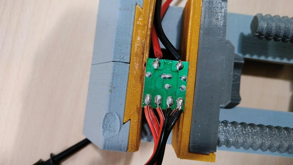
I started the week by designing a new board that I would use to connect and power a vibration motor.
I have a bunch of this motors that I recovered from old game console controls.
The idea behind designing a new board was not just to practice but also to get a step ahead into the networking week. Also, I hope to use a vibration motor in my final project.
Designing the board was actually harder then what I thought it would be as it needs some components that I don't really know how to use, like a mosfet.
So, I started by designing a board with an ATtiny412, a button, a vibration motor, a resistor and a capacitor. After that I removed the button and added a LED.
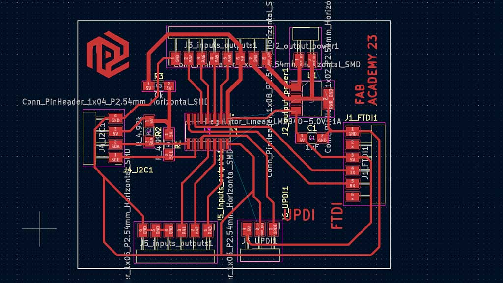
But... talking to Adrián he suggested, wisely, that I tried the ATtiny1614 instead of the ATtiny412.
Here is the ATtiny412 board:
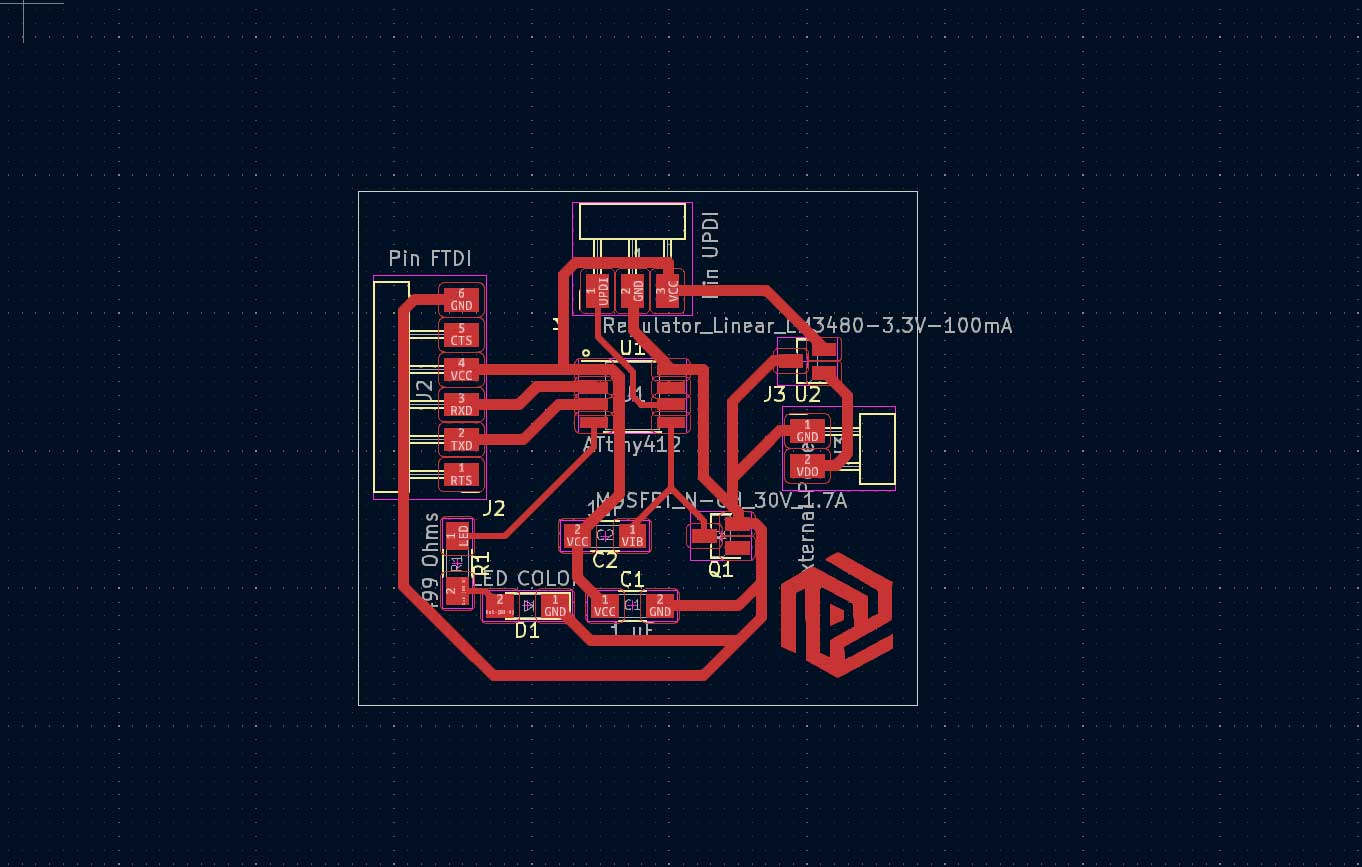
And here the board that's heavily inspired by the Adrianino.
Along the way I decided to not try the vibration motor as that would take more time. I will keep that for after Fab Academy and push the vibration motor to a second spiral.
I did have some problems making this board.
The first problem that I bumped into was an error on my part: When exporting the traces from KiCAD to Photoshop to MODS, I need to "Save as a copy" and not "Export".
This problem leads to MODS only considering a 72dpi instead of the 1000dpi needed.
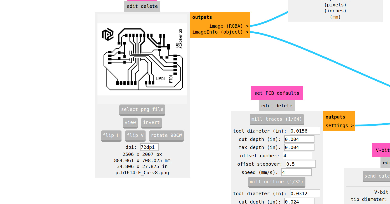
Well, silly me just made a bad conversion of the values shown and instead of the 6cm x 5cm that was supposed to be the real size of the board, I tried to mill an 80 cm by 70 cm one.
Knowledgeable Nuria came to my rescue and quickly and easily told me what the error was!
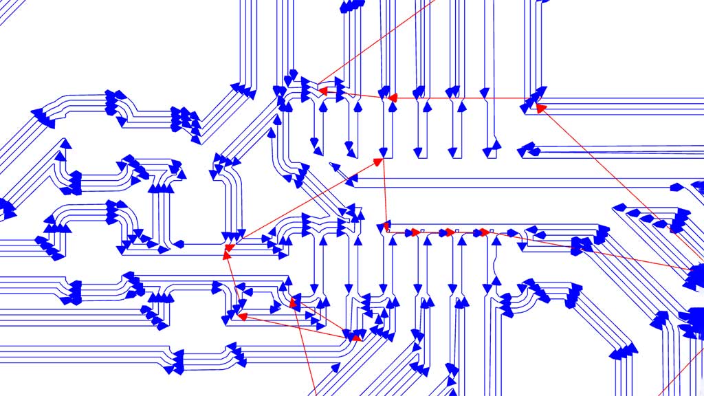
The next challenge I presented myself with was by not paying attention to details.
In Mods I need to always pay attention to the paths of the tools. That will help with avoiding a lot of grief.
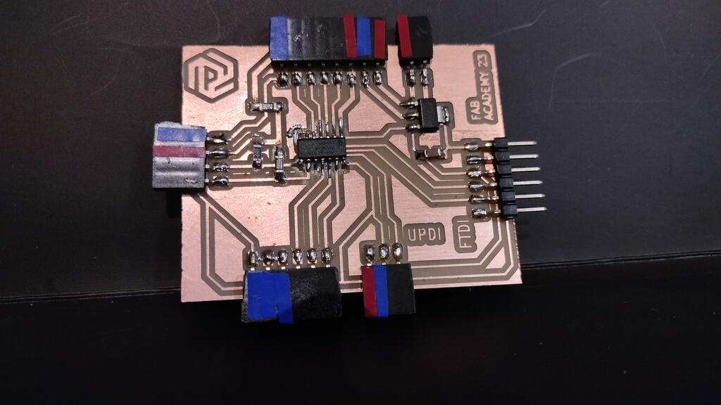
After milling the board, Adrián asked me to look at the board and quickly realized that the terminals were connected...
I am lucky to have this amazing team here in León always available to help and teach.
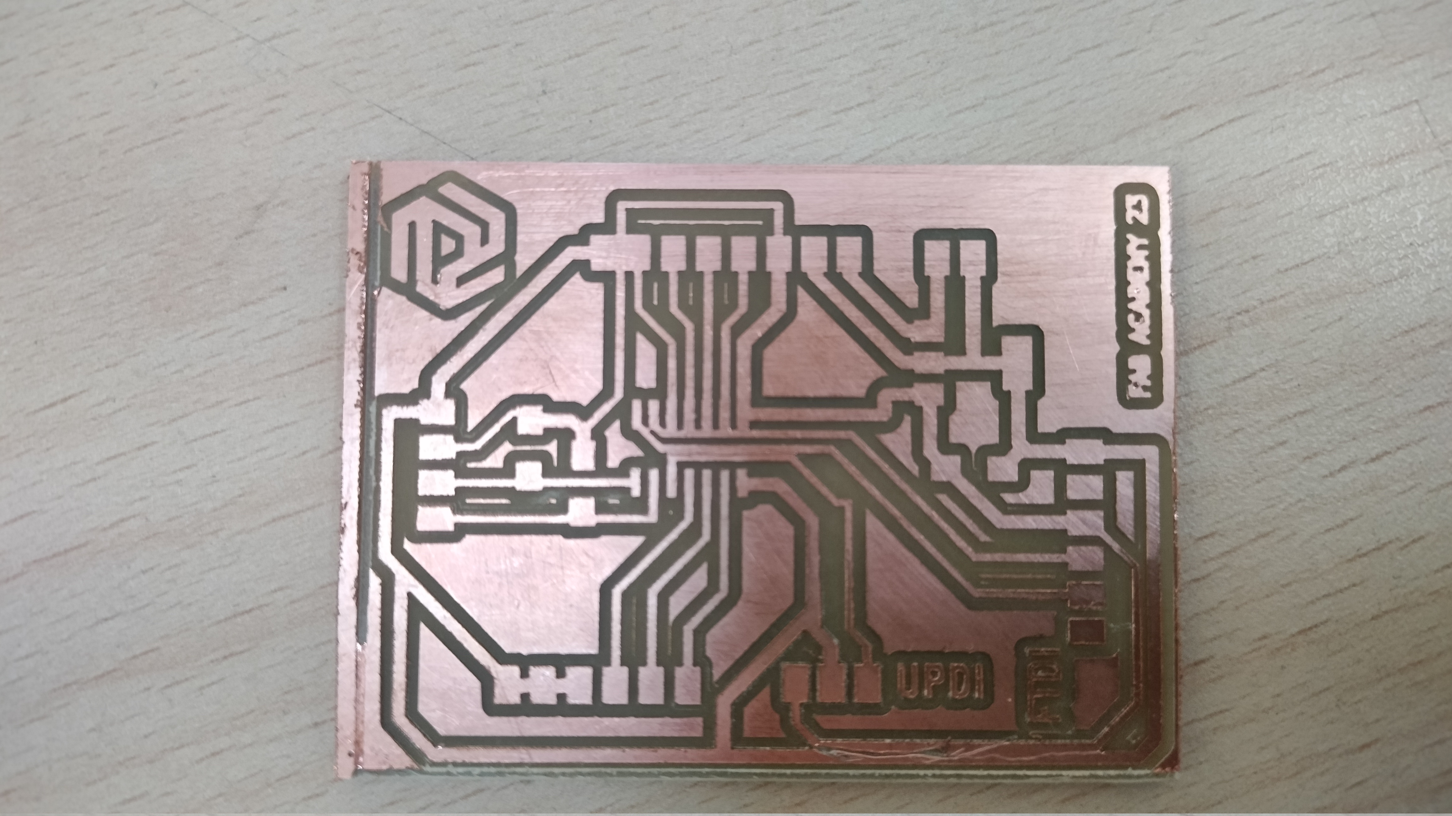
So I went back to Kicad and separate the tracks. That was only possible by turning off the option to snap the tracks to a grid.
Now because this is a new micrcontroler for me, I get to read the datasheet and here's a table with the important stuff:
| ATtiny 1614 | |
|---|---|
| Processor | 8-bit AVR processor |
| Flash | 16 KB |
| Max clock rate | Two internal clocks 16 and 20 MHz |
| GPIOs | 14 |
| EEPROM | 256 B |
| SRAM | 2 KB |
| Maximum voltage | 6V; |
| Digital pins: | PA0, PA1, PA2, PA3, PA4, PA5, PA6, PA7. Port B: PB0, PB1, PB2, PB3; |
| Analog pins: | PA1, PA2, PA3, PA4, PA5, PA6, PA7. Port B: PB0, PB1; |
| UPDI: | Programming pin: PA0 (physical pin number 10); |
| External Clock Pin: | PA3; |
| I/O | All I/O pins can be configured with internal pullup resistance; |
| USART | It has the RX (PB2 or PA2) and the TX (PB3 or PA1); |
| SPI | MOSI (PA1), MISO (PA2), SCK (PA3), SS (PA4); |
| TWI | (I2C): It has SDA (PB1 or PA1) and SCL (PB0 or PA2); |
| Site | ATtiny 1614 site |
| Datasheet | ATtiny 1614 |
Now, on with the assignment:
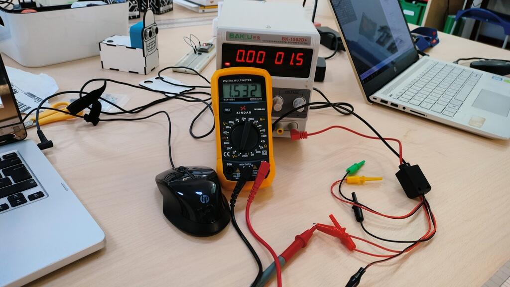
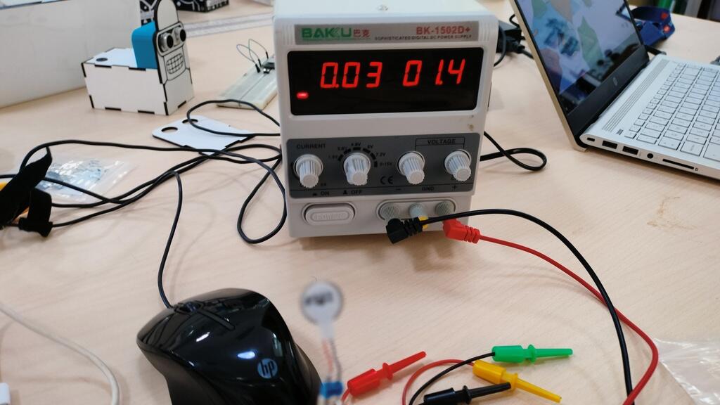
I tried to find out the voltage of the vibration motor.
I hooked up each leg to my bench power supply but no luck!
I tried everything that I could think of, and Adrián, as the Ninja that he is, gave me a lot of ideas to try, but none of them worked.... untill...
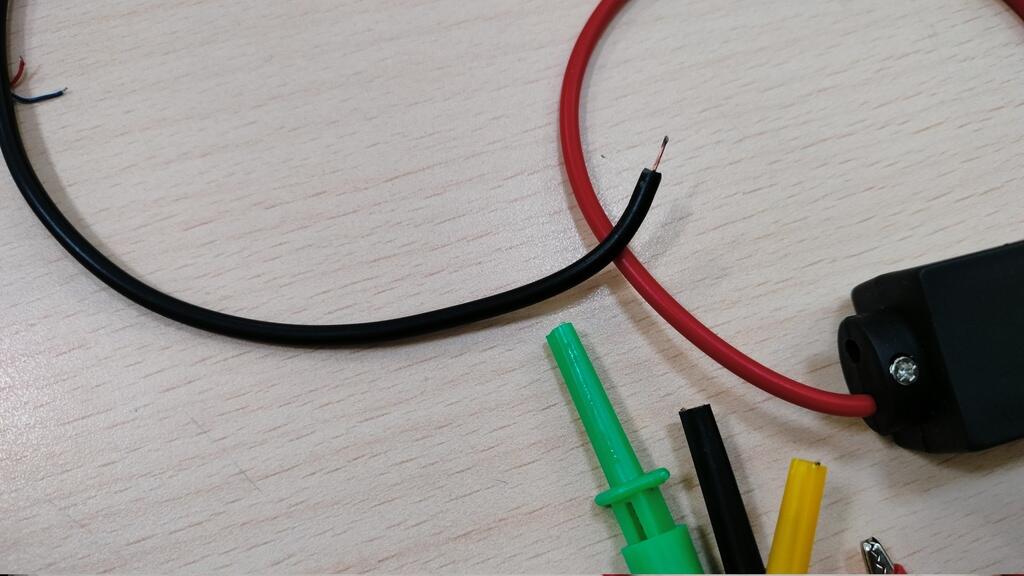
The cable popped off. It was not soldered correctly!
I disassembled the cable connector and soldered it again.
Success! Vibration at last!
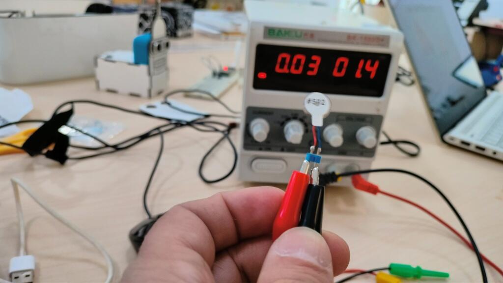
It's not out of focus, it's vibrating.
It vibrates with a 1.4V/1.5V input. I used the multimeter to check.
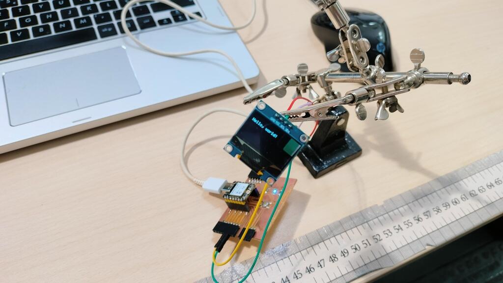
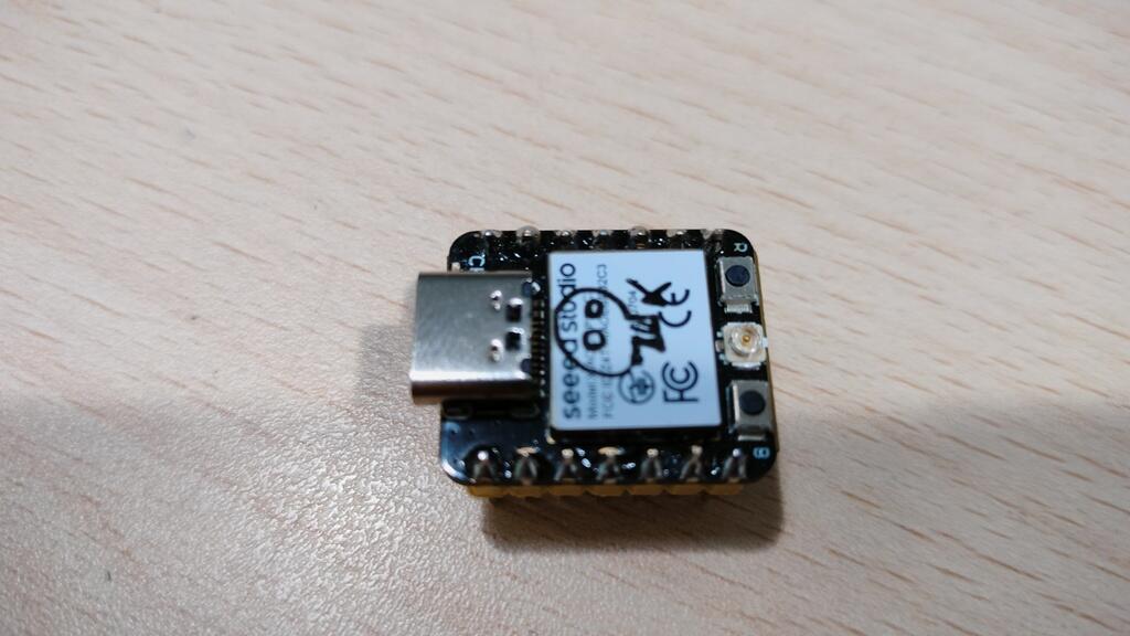
So now I will try to measure the power consumption of the board I design to swap XIAO's with a XIAO ESP32 and a 1.3" OLED display:
But...
The OLED was not turning on when connected to the bench power supply, so I started small and increased the voltage leading to me frying the ESP32!
It was a sad moment, but I learned a lot from it.
When connected the XIAO doesn't show up in any ports and starts to heat up a lot.
I tried to
Another setback, now I will have to solder pins to another board, this time the XIAO RP2040.
It only needs 3.7V to turn the display on.
It's really hard to take pictures while holding cables, banana connectors and a mobile phone. But here is another picture:
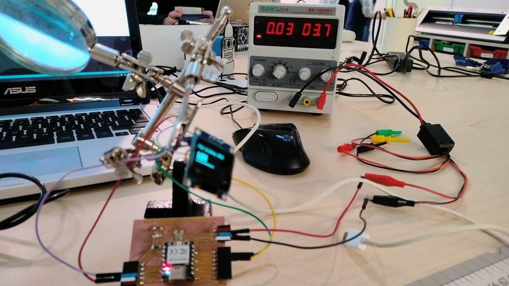
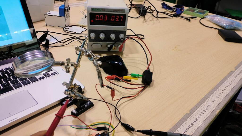
I tested it using the multimeter to get a more perfect reading of the milliamps:
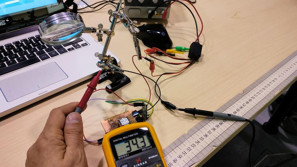
The formula for power consumption is the following: P = V x I.
We need to transform milliamps to amps: 34.3/1000 = 0.034 A
P = 3.7 x 0.034 = 0,1258 W.
But the power fluctuates as the OLED changes:
I stoled this code from the great Luis Díaz-Faes! The link is the description
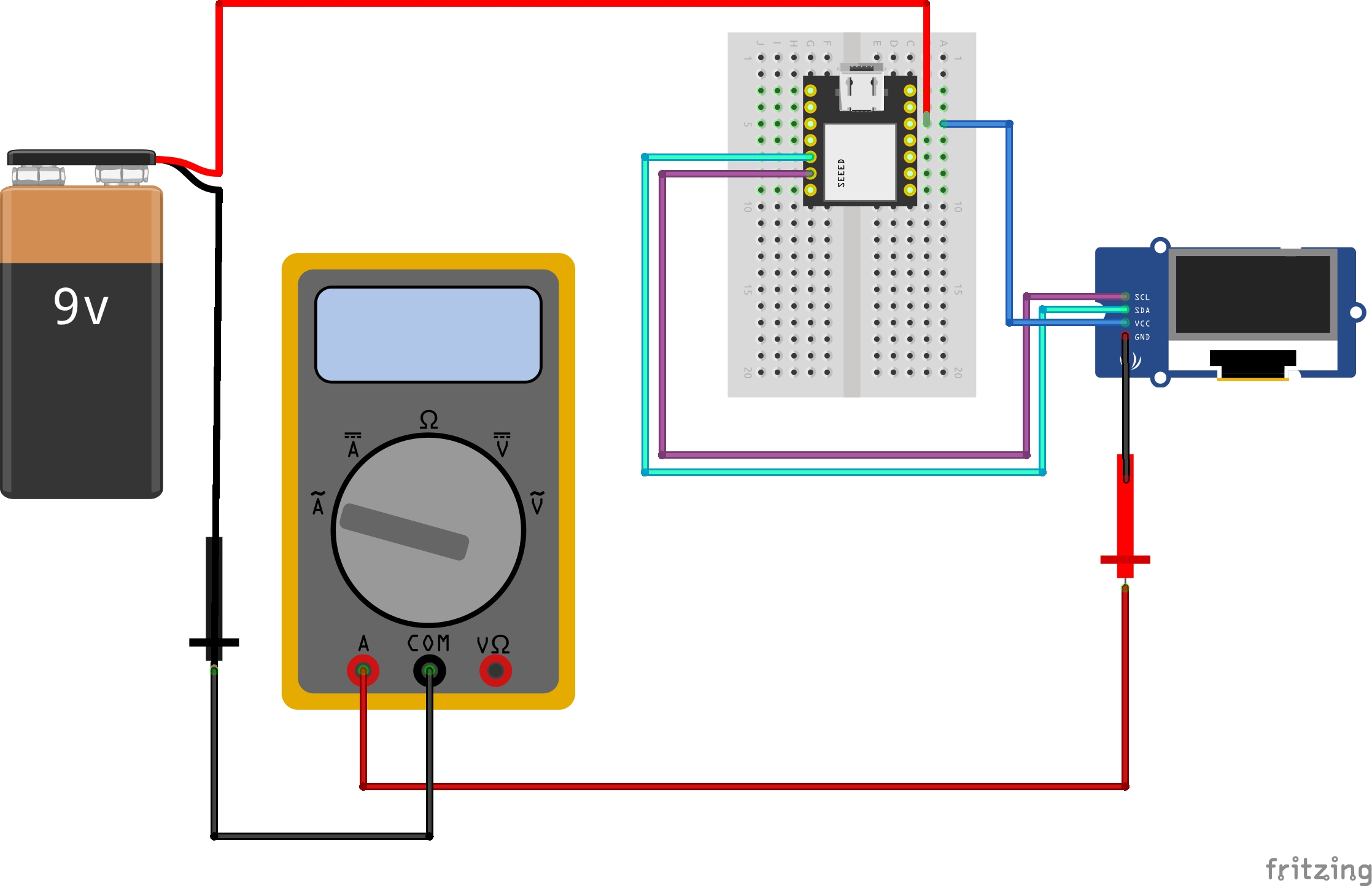
Here is the schematic of the connections for a better understanding.
(Please disregard the position of the handle on the multimeter. I just didn't find the correct image with the handle on the continuity setting):
I wanted to know how much does the board and the led use up, so I just remove the OLED display:
We need to transform milliamps to amps: 34.3/1000 = 0.034 A
P = 3.7 x 0.0275 = 0,10175 W.
If I wanted to know how much the OLED uses just by itself I would subtract the values.
The code:
    #include <Wire.h>
    #include <Adafruit_GFX.h>
    #include <Adafruit_SSD1306.h>

    #define SCREEN_WIDTH 128 // OLED display width, in pixels
    #define SCREEN_HEIGHT 64 // OLED display height, in pixels

    // Declaration for an SSD1306 display connected to I2C (SDA, SCL pins)
    Adafruit_SSD1306 display(SCREEN_WIDTH, SCREEN_HEIGHT, &Wire, -1);

    int ledR = 1;
    int numero = 0;
    int suma =  1;
    void setup() {
        Serial.begin(115200);

        if (!display.begin(SSD1306_SWITCHCAPVCC, 0x3C)) { // Address 0x3D for 128x64
        Serial.println(F("SSD1306 allocation failed"));
        for (;;);
        }

        display.clearDisplay();
        display.setTextSize(1);
        display.setTextColor(WHITE);
        display.setCursor(0, 10);
        // Display static text
        display.println("Hello, world!");
        display.println("Fab Academy 2023");
        display.display();
        delay(2000);
        pinMode(ledR, OUTPUT);
    }

    void loop() {
        numero = numero + suma;

        display.clearDisplay();
        display.setTextSize(1);
        display.setTextColor(WHITE);
        display.setCursor(0, 10);
        display.println("Fab Academy 2023");
        // Display static text

        display.setCursor(0, 30);
        display.setTextSize(2);
        display.println(numero);

        display.drawLine(0, 50, numero/2, 50, SSD1306_WHITE);
        display.display();
        analogWrite(ledR, numero);

        if (numero >= 255) {
        suma = -1;
        }
        if (numero <= 0) {
        suma = 1;
        }

    }
For the Final project
I measure the consumption of an ESP32 and OLED display. That will be useful in the future.
Files
- PCB Attiny 1614 -Kicad,Traces, DSN and PNG
- Arduino Sketch to measure power in OLED screen based on Luis Díaz-Faes code!
Learned this week (in no special order)
- How to destroy an ESP32.
- How to power a XIAO RP2040 and a XIAO ESP32 from a bench power supply.
- How to measure power consumption.
Notes and thoughts about this week's assignment.
Measuring power consumption is not a hard tasks, but what is hard is understanding what does that power consumption mean;
I will have to do a lot of math to understand the power needs of my project;
Always add a LED to the boards. It's an easy way to see if they work.
It's hard to take pictures while holding cables, banana connectors and a mobile phone. I will have to print a Phone support.
Links
- Luis Díaz-Faes Fab academy site
- Adrián Torres Fab academy site
- Espressif Tools
- Lorena Delgado Fab Academy page
Glossary:
Power: Power is the rate at which energy is used or transformed.
Energy: Energy is the capacity to do work.
Work: Work is the force exerted on an object that causes it to move.
Force: Force is a push or pull.
Efficiency: Efficiency is the percentage of the input energy that is converted to useful output energy.
Voltage: Voltage is the difference in electric potential between two points.
Current: Current is the rate of flow of electric charge.
Power: Power is the rate at which energy is used or transformed.
Resistance: Resistance is the opposition to the flow of electric current.
Power Supply: Power Supply is a device that supplies electrical energy to an electrical load.
Power Consumption: Power Consumption is the rate at which electrical energy is being used by an electrical device.
Power Efficiency: Power Efficiency is the percentage of the input power that is converted to useful output power.
Power Factor: Power Factor is a dimensionless number that indicates the relationship between the real and reactive components of the power.
Reactive Power: Reactive Power is the imaginary component of power that does not perform work.
Real Power: Real Power is the component of power that does perform work.
Energy Consumption: Energy Consumption is the amount of energy that is used by an electrical device.
Energy Efficiency: Energy Efficiency is the percentage of the input energy that is converted to useful output energy.
Energy Factor: Energy Factor is the ratio of useful output energy to input energy.
Energy Storage: Energy Storage is the process of storing energy.