This week's fun assignment was:
Group assignment:- Probe an input device(s)'s analog and digital signals
- Document your work on the group work page and reflect on your individual page what you learned
- Measure something: add a sensor to a microcontroller board that you have designed and read it.
Input devices
What I did this week
Group assignment
- Probe an input device(s)'s analog and digital signals
- Document your work on the group work page and reflect on your individual page what you learned
For the group assignment I documented the use of a Phototransistor sensor.
This sensor is a lender from Adrian Torres, code came from his site as well.
I will be using the Oscilloscope documented in the Electronics design week.
First the Sketch:
        //Fab Academy 2020 - Fab Lab León
        //Phototransistor
        //Adrianino
        //ATtiny1614 - ATtiny1624

        int sensorPin = 0;    // analog input pin to hook the sensor to
        int sensorValue = 0;  // variable to store the value coming from the sensor

        void setup() {
        Serial.begin(115200); // initialize serial communications
        }

        void loop() {
            sensorValue = analogRead(sensorPin); // read the value from the sensor
            sensorValue = map(sensorValue, 0, 1024, 1024, 0);
            Serial.println(sensorValue); // print value to Serial Monitor
            //mySerial.println("x"); // print value "x" to Serial Monitor
            delay(500); // short delay so we can actually see the numbers
        }
This is the output of the sensor when we cover it. The higher value means less light.
And in the video we can see the Oscilloscope and the wave.
This next video is just and explanation of what I'm doing with the "feet".
Please note that I didn't cover the sensor with a hand but with a special tool made in Fab Lab León to cover sensors.
Individual assignment
- Measure something: add a sensor to a microcontroller board that you have designed and read it.
For this individual assignment I will be using and testing various sensors that I hope I will use for the final project.
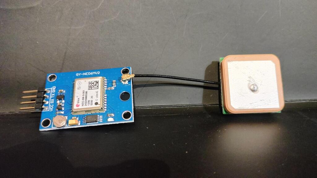
GPS Sensor
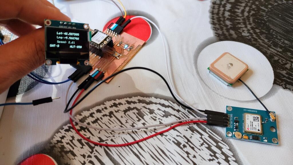
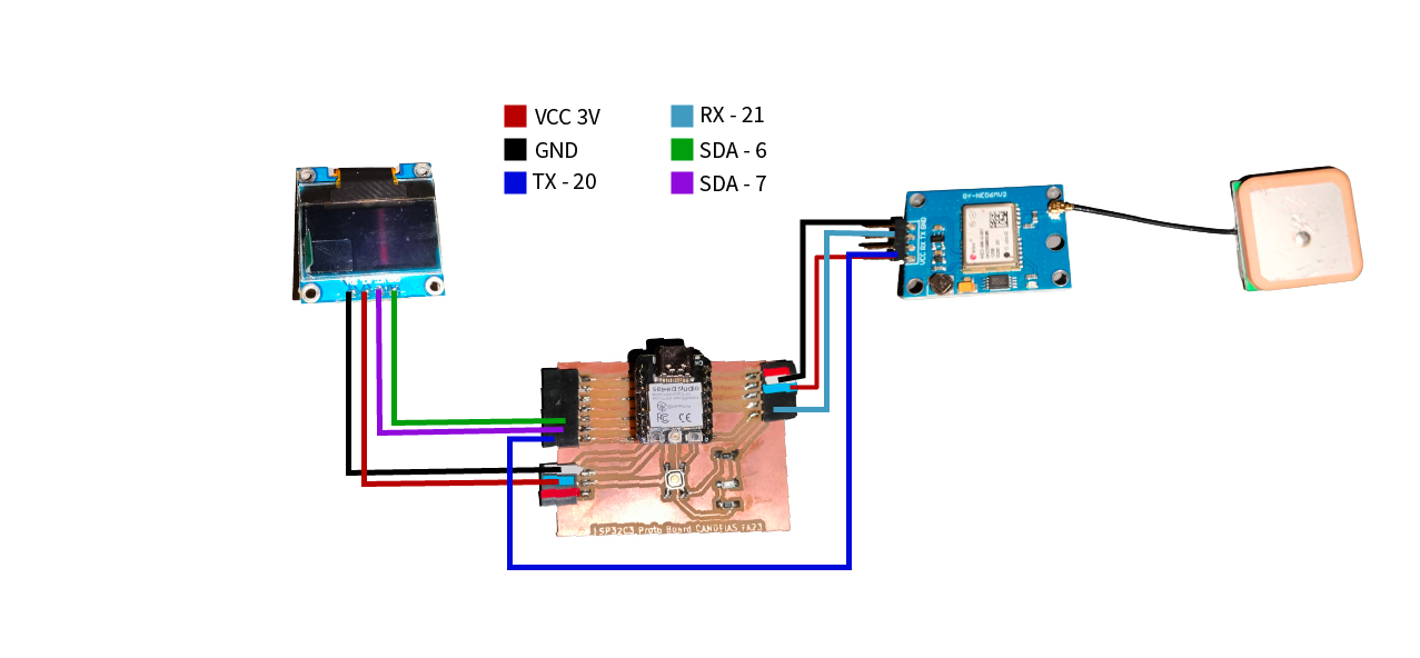
I'm going to use a XIAO ESP32 on the board I design a few weeks back, connected to a U-Blox GPS NEO-6M
Here is the connection schematic with the GPS sensor and OLED connected to the XIAO ESP32C3.
First I will try to get a fix on satelites.
For this and to decode the messages from the GPS I will be using the TinyGPS++ library.
I will run this Arduino Sketch. You can find it in the Files section:
This particular code also uses other libraries for the OLED display.
/*
* Based on a Sketch from Rui Santos from https://randomnerdtutorials.com
* Based on the example TinyGPS++ from arduiniana.org
*
*/

#include <TinyGPS++.h>
#include <SoftwareSerial.h>
#include <Wire.h>
#include <Adafruit_GFX.h>
#include <Adafruit_SSD1306.h 	>
#define SCREEN_WIDTH 128 // OLED display width, in pixels
#define SCREEN_HEIGHT 64 // OLED display height, in pixels
static const int RXPin = 20, TXPin = 21;
static const uint32_t GPSBaud = 9600;

// Declaration for an SSD1306 display connected to I2C (SDA, SCL pins)
Adafruit_SSD1306 display(SCREEN_WIDTH, SCREEN_HEIGHT, &Wire, -1);
// The TinyGPS++ object
TinyGPSPlus gps;

// The serial connection to the GPS device
SoftwareSerial ss(RXPin, TXPin);

void setup(){
  Serial.begin(9600);
  ss.begin(GPSBaud);
  if(!display.begin(SSD1306_SWITCHCAPVCC, 0x3C)) {
    Serial.println(F("SSD1306 allocation failed"));
    for(;;);
  }
  delay(2000);
  display.clearDisplay();
  display.setTextColor(WHITE);
}

void loop(){

  boolean newData = false;
  for (unsigned long start = millis(); millis() - start < 1000;)
  {<
    while (ss.available())
    {
      if (gps.encode(ss.read()))
      {
        newData = true;
      }
    }
  }

  //If newData is true
  if(newData == true)
  {
    newData = false;
    Serial.println(gps.satellites.value());

  }
}
It's true that it already has the OLED interface but that was just for testing purposes.
Here's a video:
Now I will try to get the coordinates.
/*
* Based on a Sketch from Rui Santos from https://randomnerdtutorials.com
* Based on the example TinyGPS++ from arduiniana.org
*
*/

#include <TinyGPS++.h>
#include <SoftwareSerial.h>
TinyGPSPlus gps;
SoftwareSerial ss(20, 21);

void setup(){
  Serial.begin(9600);
  ss.begin(9600);
}

void loop(){
  // This sketch displays information every time a new sentence is correctly encoded.
  while (ss.available() > 0){
    gps.encode(ss.read());
    if (gps.location.isUpdated()){
      // Latitude in degrees (double)
      Serial.print("Latitude= ");
      Serial.print(gps.location.lat(), 6);
      // Longitude in degrees (double)
      Serial.print(" Longitude= ");
      Serial.println(gps.location.lng(), 6);

      // Raw latitude in whole degrees
      Serial.print("Raw latitude = ");
      Serial.print(gps.location.rawLat().negative ? "-" : "+");
      Serial.println(gps.location.rawLat().deg);
      // ... and billionths (u16/u32)
      Serial.println(gps.location.rawLat().billionths);

      // Raw longitude in whole degrees
      Serial.print("Raw longitude = ");
      Serial.print(gps.location.rawLng().negative ? "-" : "+");
      Serial.println(gps.location.rawLng().deg);
      // ... and billionths (u16/u32)
      Serial.println(gps.location.rawLng().billionths);

      // Raw date in DDMMYY format (u32)
      Serial.print("Raw date DDMMYY = ");
      Serial.println(gps.date.value());

      // Year (2000+) (u16)
      Serial.print("Year = ");
      Serial.println(gps.date.year());
      // Month (1-12) (u8)
      Serial.print("Month = ");
      Serial.println(gps.date.month());
      // Day (1-31) (u8)
      Serial.print("Day = ");
      Serial.println(gps.date.day());

      // Raw time in HHMMSSCC format (u32)
      Serial.print("Raw time in HHMMSSCC = ");
      Serial.println(gps.time.value());

      // Hour (0-23) (u8)
      Serial.print("Hour = ");
      Serial.println(gps.time.hour());
      // Minute (0-59) (u8)
      Serial.print("Minute = ");
      Serial.println(gps.time.minute());
      // Second (0-59) (u8)
      Serial.print("Second = ");
      Serial.println(gps.time.second());
      // 100ths of a second (0-99) (u8)
      Serial.print("Centisecond = ");
      Serial.println(gps.time.centisecond());

      // Raw speed in 100ths of a knot (i32)
      Serial.print("Raw speed in 100ths/knot = ");
      Serial.println(gps.speed.value());
      // Speed in knots (double)
      Serial.print("Speed in knots/h = ");
      Serial.println(gps.speed.knots());
      // Speed in miles per hour (double)
      Serial.print("Speed in miles/h = ");
      Serial.println(gps.speed.mph());
      // Speed in meters per second (double)
      Serial.print("Speed in m/s = ");
      Serial.println(gps.speed.mps());
      // Speed in kilometers per hour (double)
      Serial.print("Speed in km/h = ");
      Serial.println(gps.speed.kmph());

      // Raw course in 100ths of a degree (i32)
      Serial.print("Raw course in degrees = ");
      Serial.println(gps.course.value());
      // Course in degrees (double)
      Serial.print("Course in degrees = ");
      Serial.println(gps.course.deg());

      // Raw altitude in centimeters (i32)
      Serial.print("Raw altitude in centimeters = ");
      Serial.println(gps.altitude.value());
      // Altitude in meters (double)
      Serial.print("Altitude in meters = ");
      Serial.println(gps.altitude.meters());
      // Altitude in miles (double)
      Serial.print("Altitude in miles = ");
      Serial.println(gps.altitude.miles());
      // Altitude in kilometers (double)
      Serial.print("Altitude in kilometers = ");
      Serial.println(gps.altitude.kilometers());
      // Altitude in feet (double)
      Serial.print("Altitude in feet = ");
      Serial.println(gps.altitude.feet());

      // Number of satellites in use (u32)
      Serial.print("Number of satellites in use = ");
      Serial.println(gps.satellites.value());

      // Horizontal Dim. of Precision (100ths-i32)
      Serial.print("HDOP = ");
      Serial.println(gps.hdop.value());
    }
  }
}
Here's the video:
We are just getting raw information, like:
15:59:28.937 -> Raw latitude = +42
15:59:28.937 -> 598234000
15:59:28.937 -> Raw longitude = -5
15:59:28.937 -> 566503500
15:59:28.937 -> Raw date DDMMYY = 170423
15:59:28.937 -> Year = 2023
15:59:28.937 -> Month = 4
15:59:28.937 -> Day = 17
15:59:28.937 -> Raw time in HHMMSSCC = 13592800
Now I will decode this information and present it out the OLED Display.
/*
* Based on a Sketch from Rui Santos from https://randomnerdtutorials.com
* Based on the example TinyGPS++ from arduiniana.org
*
*/

#include <TinyGPS++.h>
#include <SoftwareSerial.h>
#include <Wire.h>
#include <Adafruit_GFX.h>
#include <Adafruit_SSD1306.h>
#define SCREEN_WIDTH 128 // OLED display width, in pixels
#define SCREEN_HEIGHT 64 // OLED display height, in pixels
static const int RXPin = 20, TXPin = 21;
static const uint32_t GPSBaud = 9600;

// Declaration for an SSD1306 display connected to I2C (SDA, SCL pins)
Adafruit_SSD1306 display(SCREEN_WIDTH, SCREEN_HEIGHT, &Wire, -1);
// The TinyGPS++ object
TinyGPSPlus gps;

// The serial connection to the GPS device
SoftwareSerial ss(RXPin, TXPin);

void setup(){
  Serial.begin(9600);
  ss.begin(GPSBaud);
  if(!display.begin(SSD1306_SWITCHCAPVCC, 0x3C)) {
    Serial.println(F("SSD1306 allocation failed"));
    for(;;);
  }
  delay(2000);
  display.clearDisplay();
  display.setTextColor(WHITE);
}

void loop(){

  boolean newData = false;
  for (unsigned long start = millis(); millis() - start < 1000;)
  {
    while (ss.available())
    {
      if (gps.encode(ss.read()))
      {
        newData = true;
      }
    }
  }

  //If newData is true
  if(newData == true)
  {
    newData = false;
    Serial.println(gps.satellites.value());
    print_speed();
  }
  else
  {
    display.clearDisplay();
    display.setTextColor(SSD1306_WHITE);
    display.setCursor(0, 0);
    display.setTextSize(3);
    display.print("No Data");
    display.display();
  }
}

void print_speed()
{
  display.clearDisplay();
  display.setTextColor(SSD1306_WHITE);
  if (gps.location.isValid() == 1)
  {
  //String gps_speed = String(gps.speed.kmph());
    display.setTextSize(1);


    display.setCursor(25, 5);
    display.print("Lat: ");
    display.setCursor(50, 5);
    display.print(gps.location.lat(),6);

    display.setCursor(25, 20);
    display.print("Lng: ");
    display.setCursor(50, 20);
    display.print(gps.location.lng(),6);

    display.setCursor(25, 35);
    display.print("Speed: ");
    display.setCursor(65, 35);
    display.print(gps.speed.kmph());

    display.setTextSize(1);
    display.setCursor(0, 50);
    display.print("SAT:");
    display.setCursor(25, 50);


    display.setTextSize(1);
    display.setCursor(70, 50);
    display.print("ALT:");
    display.setCursor(95, 50);
    display.print(gps.altitude.meters(), 0);

    display.display();
  }
  else
  {
    display.clearDisplay();
    display.setTextColor(SSD1306_WHITE);
    display.setCursor(0, 0);
    display.setTextSize(3);
    display.print("No Data");
    display.display();
  }
}
So there we have it, Latitude, longitude, altitude and speed and how many satellites are connected:
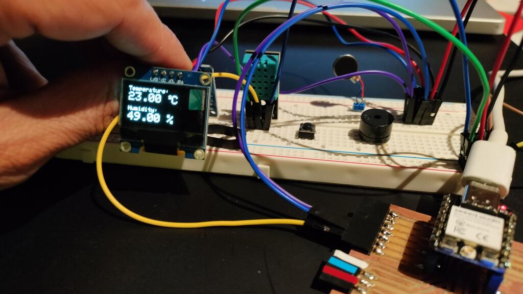
DHT11 Sensor and a OLED display
I will also be using a DHT11 sensor. I have used one before.
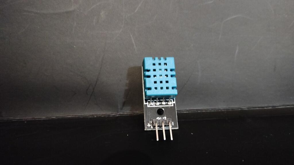
First, the connection schematic:
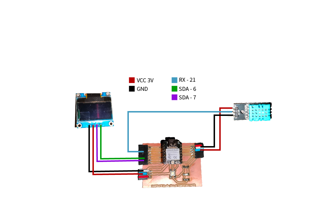
Here's the sketch:
/*
* Based on Rui Santos Sketch from https://randomnerdtutorials.com
*/

#include <Wire.h>
#include <Adafruit_GFX.h>
#include <Adafruit_SSD1306.h>
#include <Adafruit_Sensor.h>
#include <DHT.h>

#define SCREEN_WIDTH 128 // OLED display width, in pixels
#define SCREEN_HEIGHT 64 // OLED display height, in pixels

Adafruit_SSD1306 display(SCREEN_WIDTH, SCREEN_HEIGHT, &Wire, -1);

#define DHTPIN 21     // Digital pin connected to the DHT sensor
#define DHTTYPE    DHT11<
DHT dht(DHTPIN, DHTTYPE);

void setup() {
  Serial.begin(115200);

  dht.begin();

  if(!display.begin(SSD1306_SWITCHCAPVCC, 0x3C)) {
    Serial.println(F("SSD1306 allocation failed"));<
  display.setTextColor(WHITE);
}
}

void loop() {
  delay(5000);

  //read temperature and humidity
  float t = dht.readTemperature();
  float h = dht.readHumidity();
  if (isnan(h) || isnan(t)) {
    Serial.println("Failed to read from DHT sensor!");
  }
  // clear display
  display.clearDisplay();

  // display temperature
  display.setTextSize(1);
  display.setCursor(0,0);
  display.print("Temperature: ");
  display.setTextSize(2);
  display.setCursor(0,10);
  display.print(t);
  display.print(" ");
  display.setTextSize(1);
  display.cp437(true);
  display.write(167);
  display.setTextSize(2);
  display.print("C");

  // display humidity
  display.setTextSize(1);
  display.setCursor(0, 35);
  display.print("Humidity: ");
  display.setTextSize(2);
  display.setCursor(0, 45);
  display.print(h);
  display.print(" %");
  display.display();
}
Running the sketch we will get something like this:
And the end result:
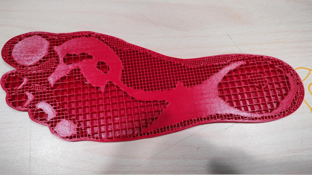
Velostat: Force Sensitive Resistor
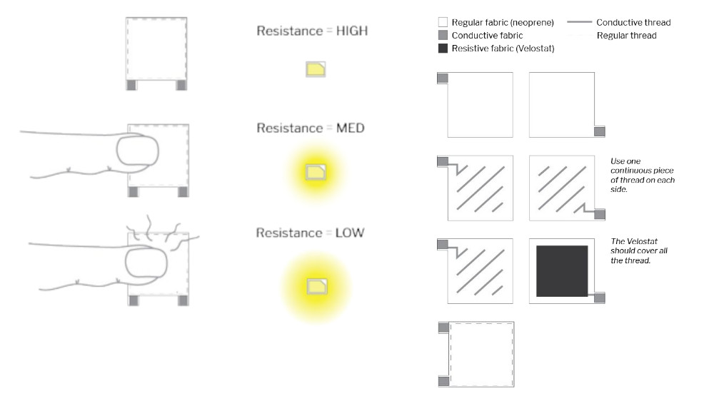
Velostat is a black plastic sheet which is pressure-sensitive and conductive. It can be used to detect force on its surface because the conductivity changes when the pressure on the material changes.
The sensor consists of a piece of velostat and a conductive material of smaller size, with a thin air gap between them. When pressure is applied to the sensor, the conductor comes in contact with the velostat. As more pressure is applied a greater surface area of the conductor makes contact with the velostat.
This contact improves as they are pressed together, resulting in a reduction in electrical resistance between the two. This behavior enables us to detect the amount of force exerted on the sensor.
Here is an explanation taken from Liza Start/FabriAcademy (link in the links section.
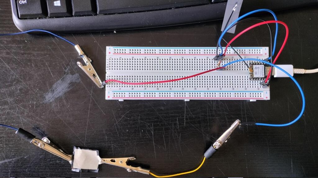
And here is the sensor I made.
This is the sketch to measure the resistance:
  int fsPin = 3;
  int fsReading;

  void setup() {
  Serial.begin(9600);
  }

  void loop() {
    fsReading = analogRead(fsPin);
    Serial.print("Analog reading=");
    Serial.println(fsReading);
    if (fsReading < 100)       // from 0 to 9
      Serial.println(" -> Very high pressure");
    else if (fsReading < 400) // from 10 to 199
      Serial.println(" -> High pressure");
    else if (fsReading < 500) // from 200 to 499
      Serial.println(" -> normal pressure");
    else if (fsReading < 800) // from 500 to 799
      Serial.println(" -> light pressure" );
    else // from 800 to 1023
      Serial.println(" -> no pressure");

    delay(1000);
  }
Running the sketch we will get the following results:
One thing that you can notice is that the values are not constant and fluctuate a lot. That is in part because this is Variable resistor but also because I should be using a 10k resistor instead of the 220ohm resistor.
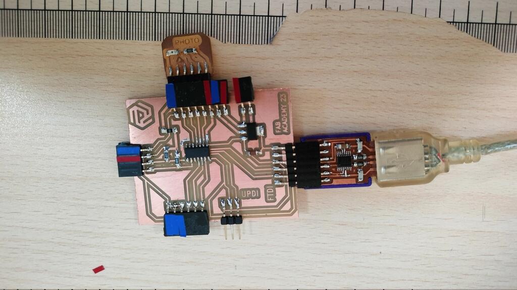
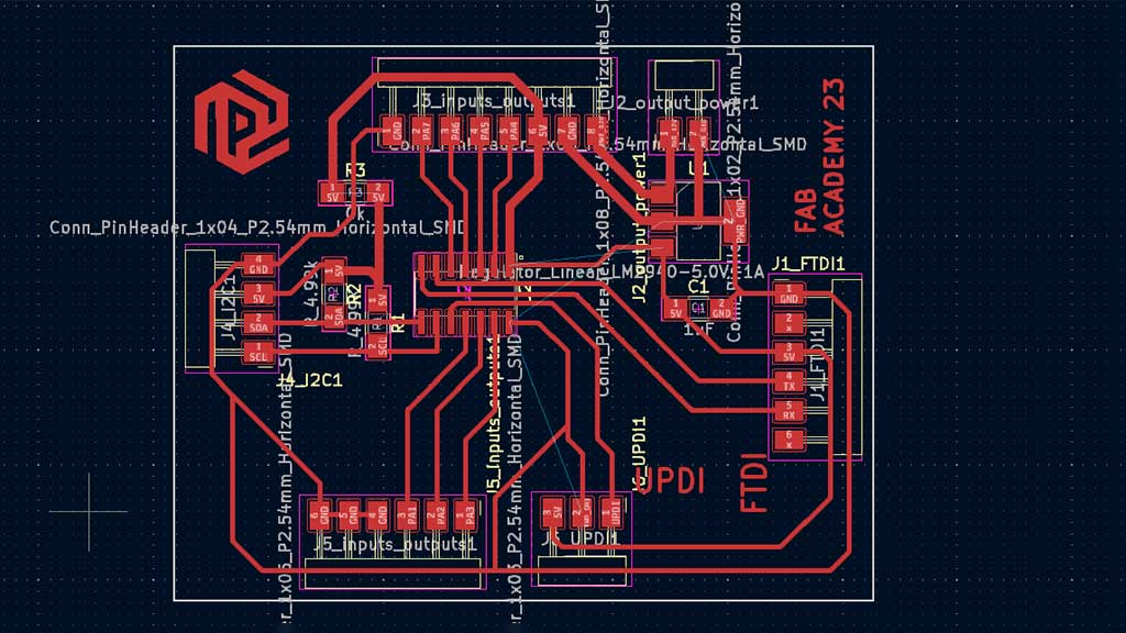
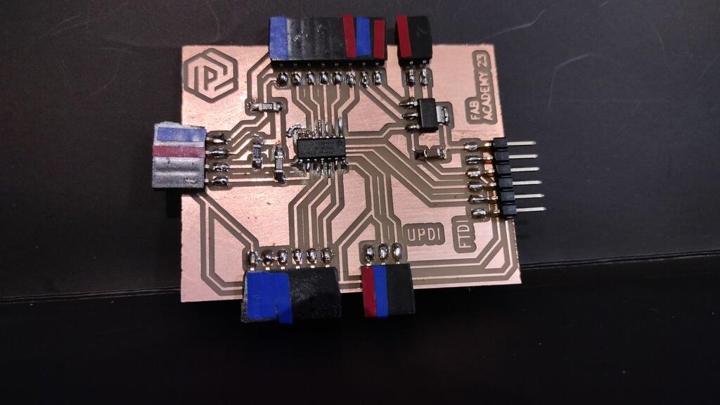
PCB with an Attiny 1614.
I want to try to use different microcontrollers. In Fab Academy I have already used the XIAO ESP32C3, a XIAO RP2040, a SAMD21 and an ATtiny412.
I designed a board based on the Adrianino for the Attiny 1614.
I will be using this board to test some more sensors:
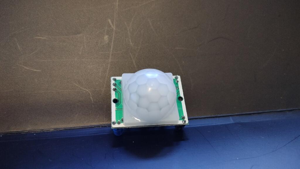
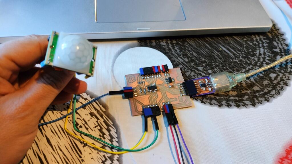
Trying the PIR sensor
The Sketch
/*
  Arduino with PIR motion sensor
  For complete project details, visit: http://RandomNerdTutorials.com/pirsensor
  Modified by Rui Santos based on PIR sensor by Limor Fried
*/

int sensor = 2;              // the pin that the sensor is attached to
int state = LOW;             // by default, no motion detected
int val = 0;                 // variable to store the sensor status (value)

void setup() {
  pinMode(sensor, INPUT);    // initialize sensor as an input
  Serial.begin(9600);        // initialize serial
}

void loop(){
  val = digitalRead(sensor);   // read sensor value
  if (val == HIGH) {           // check if the sensor is HIGH
    delay(100);                // delay 100 milliseconds

    if (state == LOW) {
      Serial.println("Motion detected!");
      state = HIGH;       // update variable state to HIGH
    }
  }
  else {
      delay(200);             // delay 200 milliseconds

      if (state == HIGH){
        Serial.println("Motion stopped!");
        state = LOW;       // update variable state to LOW
    }
  }
}
Running the sketch we will get something like this:
For the final project
The GPS with the OLED documented above.
Files
- Sketch: DHT11 Sensor with OLED
- Sketch: GPS with OLED
- PCB Attiny 1614 PCB: Kicad, Traces, SVG and PNG.
- Velostat measuring
Learned this week (in no special order)
- Don't update Arduino if everything is working!
- Verify the traces in MODS CE to make sure that they get engraved;
Notes and Thoughts
This week was riddle with simple but time consuming problems but being persistent in the pursuit of a solution did pay off at the end.
I have some loose ends on my documentation that I have to finish.
Bendy and stretchablesensors are very interesting!
Links
- Guide to NEO-6M GPS Module
- Adrianino by Adrian Torres
- Digitalwrite function
- kobakant
- FabriAcademy: Liza Stark Week 5
Glossary:
- Phototransistor: Is a device that operates by converting incoming photons to electrons in the base of a bipolar transistor.
- Photoresistor: a device that changes its resistance when exposed to light.
- LED: Light-emitting diode
- IR: Infrared
- PIR: Passive Infrared
- ADC: Analog to Digital Converter
- DAC: Digital to Analog Converter
- GPS: Global Positioning System
- LDR: Light Dependent Resistor
- RTC: Real Time Clock
- EEPROM: Electrically Erasable Programmable Read-Only Memory
Some of these definitions were generated by AI using ChatGTP.