This week's fun assignment was:
Group project:- Use the test equipment in your lab to observe the operation of a microcontroller circuit board
- Design a development board to interact and communicate with an embedded microcontroller
- Extra credit: make a case for it

Electronics design
Here is the documentation for this week's assignment.
Before I jumped into the group-me assignment I felt that I need to investigate and write down some concepts and definitions. So I started by the last section of the page, the Glossary
Electronics and it's concepts are very new to me. I know near nothing about this weeks assignments tasks, electricity and the flow of current.
It was a hard week for me has I had a lot to read and learn and as always, not that much time to do it.
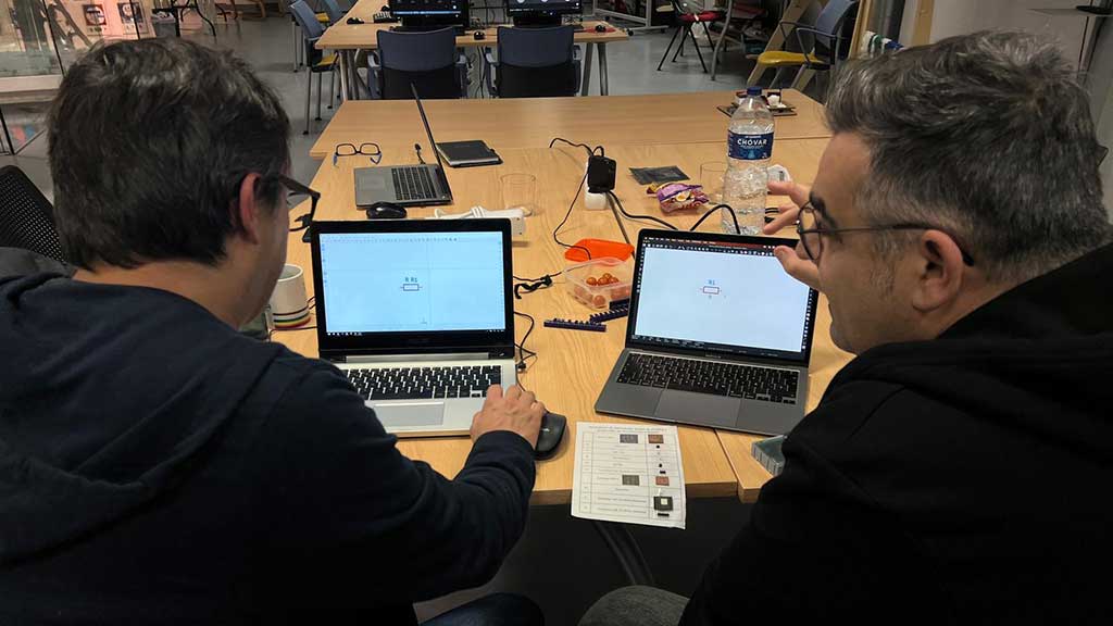
Thankfully, this week Luis Diaz-Faes came all to way from Vigo to give me a crash course on electronic design and it's components.
Luis is a former Fab Academy Student and is training to be an instructor. You can check out his Fab Academy Page here. He also runs the association A Industriosa a Citizen Technology Laboratory.
Group assignment
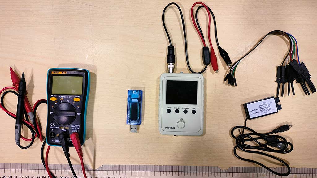
For the group assignment that will be performed by just me, I will be using the following equipment:
- Multimeter;
- Oscilloscope;
- Logic analyser;
- Voltmeter/Ampmeter
Before using the tools I listed, I watched this video from Fab Lab León about them. The link is on the links section.
It is in Spanish but I felt I should mention the video as it was quite useful in learning how to use the tools and why to use them.
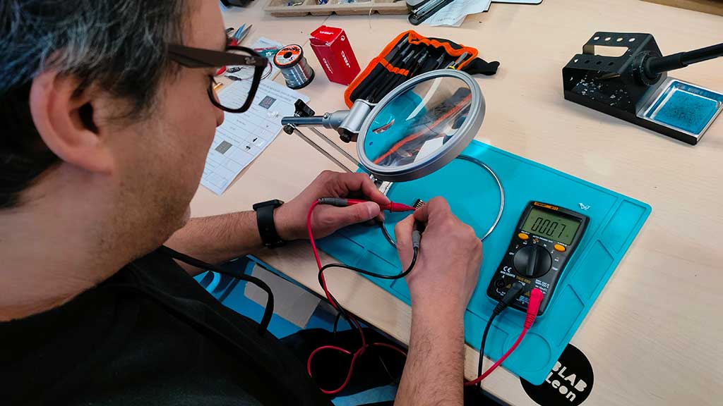
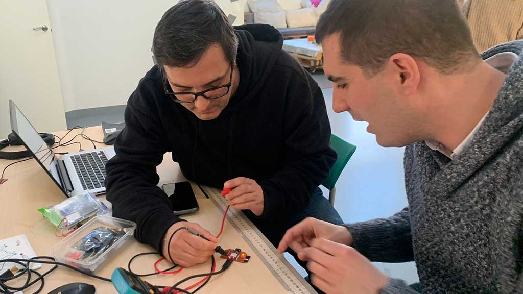
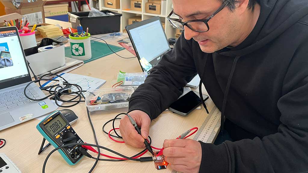
I started by trying out the Multimeter. I had the good fortune and pleasure of being accompanied by Adrian Torres and Luis as instructors.
A multimeter can measure multiple electrical values: voltage, current, resistance, as well as test for continuity.
Most multimeters have three ports: COM (or "-"), mAVΩ, and 10A. The COM stands for common and is where the black probe is plugged into. The mAVΩ port is where the red probe plugs into to measure volts, resistance, and current. The 10A port is used when measuring currents greater than 200 mA.
Important symbols
Voltage
- “V” with a wavy line over it = AC voltage.
- “V” with one dotted and one solid over it = DC voltage.
- “mV” with one wavy line or a pair of lines, one dotted and one solid, over it = AC or DC millivolts.
Current
- “A” with a wavy line over it = AC current.
- “A” with two lines, one dotted and one solid, over it = DC current.
- mA = Milliamps.
- µA (µ is the Greek letter mu) = Microamps (millionths of an amp).
Resistance
- Ω = Ohms.
- kΩ = Kilohms.
- MΩ = Mega ohms.
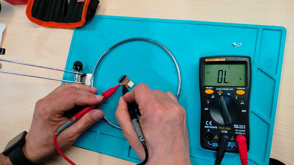
First I measured the continuity of circuits:
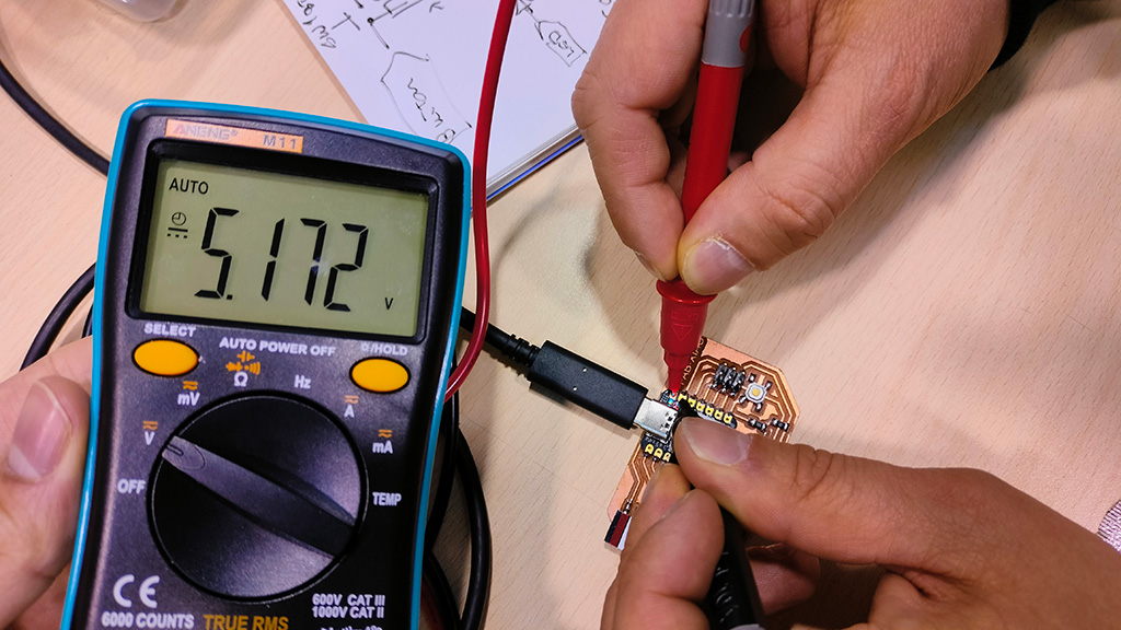
After that I measured the voltage of a microcontroller pin, in this case a XIAO RP2040 in the Fab XIAO.
Adrián teaching me how to use the Multimeter
Testing resistance
Testing with a Oscilloscope
The oscilloscope is a tool which allows to visualise an electrical signal in the form of a graph.
The x-axis represents time and the y-axis represents amplitude in volts.
Each component or system has a standard waveform.
With an Oscilloscope we can measure the following things:
- Frequency of the signal;
- Period of the signal;
- Amplitude of the signal;
- Positive and negative peaks of the signal;
Types os waves:
- Sine waves;
- Square and rectangular waves;
- Sawtooth and triangle waves;
- Step and pulse shapes;
- Periodic and non-periodic signals;
- Synchronous and asynchronous signals;
- Complex waves;
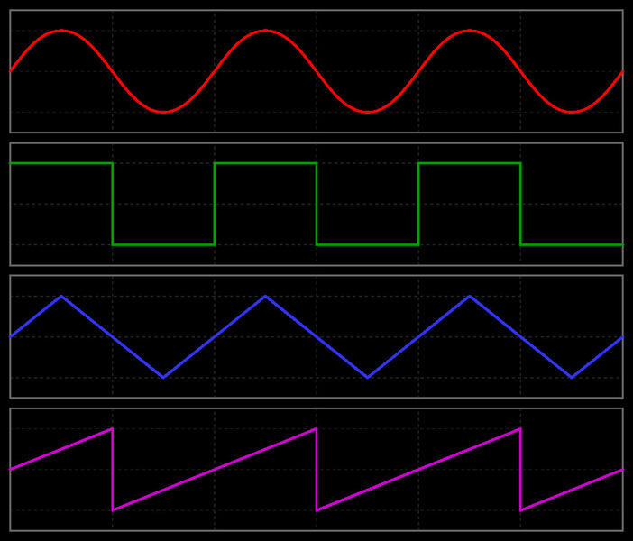
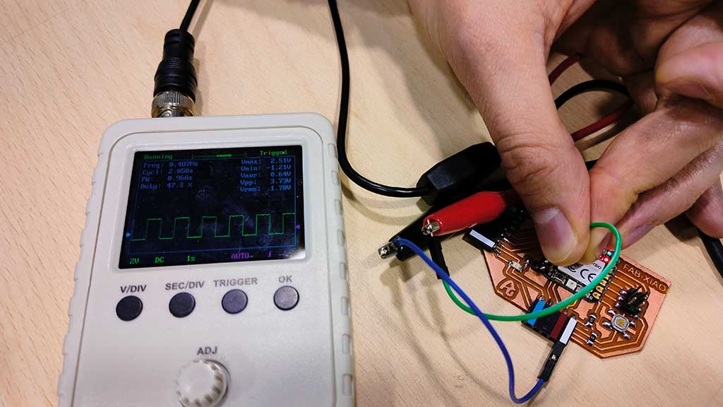
I got a square wave. A square wave is a voltage that turns on and off (or goes high and low) at regular intervals.
Television, radio, and computer circuitry often use square waves for timing signals. The rectangular wave is like the square wave except that the high and low time intervals are not of equal length.
In this case, it was related to the LED blinking on the board.
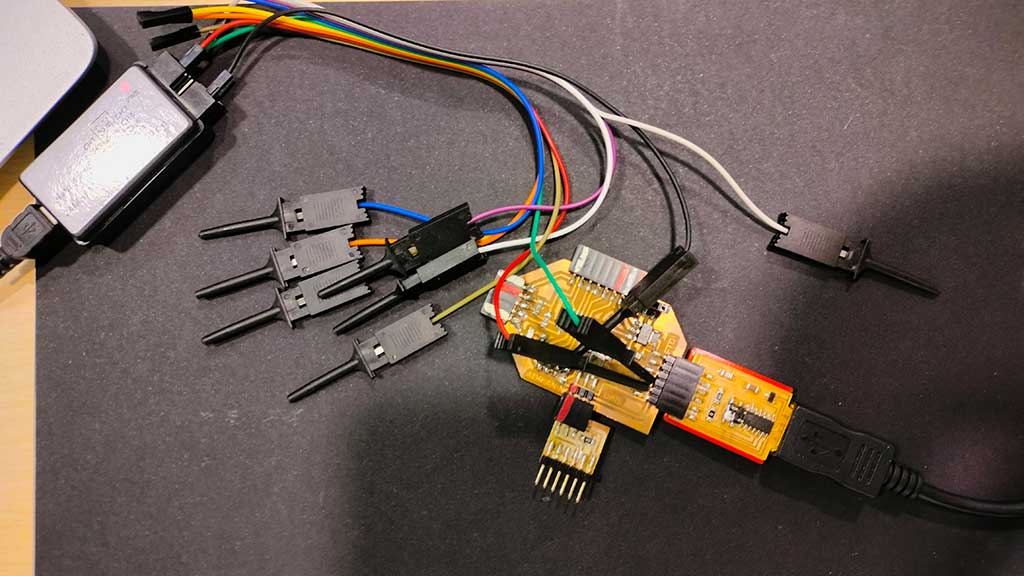
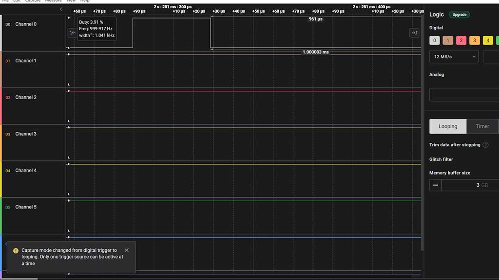
Testing with a Logic Analyser
Logic analyzers record, display, and analyze digital signals. They are used to troubleshoot and debug digital circuits.
Throught the device we can see the data that we send through FTDI, how an I2C works or simply measure the pulses of a blink and if they correspond to what we have programmed.
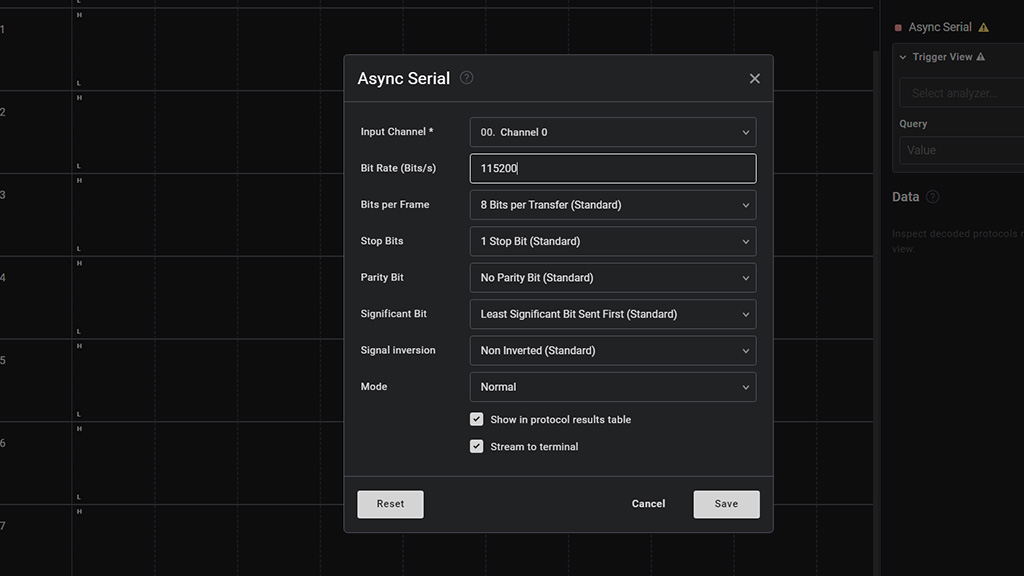
In order to test the Logic Analyzer I first installed Logic 2 software and configure it correctly.
It's open source software from Saleae.
The logic analyser is connected to 2 pins. GND and one pin as channel.
After that I tested the logic analyser with a simple circuit with the pulse of a led.
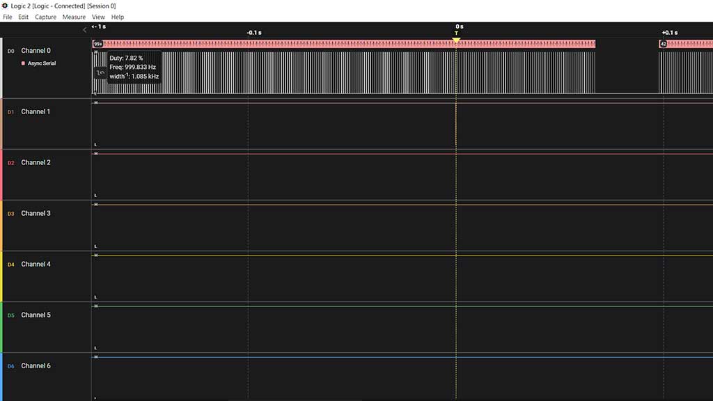
Zooming in:
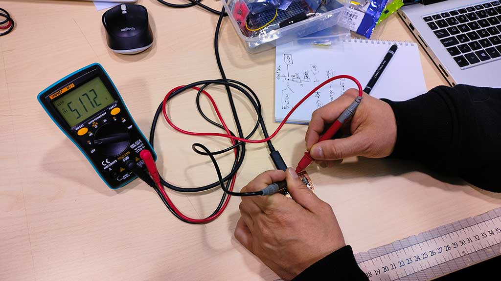
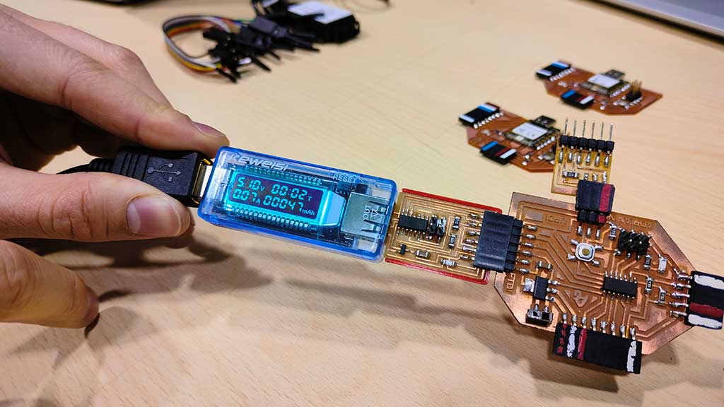
Testing with a Voltmeter/Ampmeter
A voltmeter is used to measure electrical potential difference between two points in an electrical circuit. An ammeter is used for measuring the electric current in a circuit.
On the next image you can see the voltage of the board
Here's a vídeo of LEDsblinking and how that interacts.
Lastly this analog but useful piece of equipment:
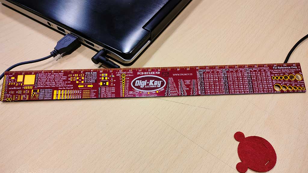
We can check the size of components with this ruler!
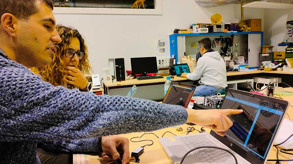
Adrián is always so very helpful. Here is a picture of him teaching Núria about his findings with the Logic Analyser.
Individual assignment
For this week's individual assignment I had to design a development board to interact and communicate with an embedded microcontroller.
Like I mentioned before, Luis came all the way from Vigo to give me a lesson on designing the development board.

The PCB uses the ATtiny412 microcontroller, a button, a led and resistors.
It's a very simple board but it's a good start.
I used Kicad for the design, but first I needed to import the Fab Library. The link for the Fab Library is on the links sections.
- Clone or download the repository. Rename the directory to
fab. - Store it in a safe place such as
~/kicad/libraries. - Run KiCad or open a KiCad
.profile. - Go to "Preferences / Manage Symbol Libraries" and add
fab.kicad_symas symbol library. - Go to "Preferences / Manage Footprint Libraries" and add
fab.prettyas footprint library. - Go to "Preferences / Configure Paths" and add a variable named FAB that points to the
installation directory of the fab library, such as
~/kicad/libraries/faborC:/kicad/libraries/fab. This will enable the custom 3D shapes to be found. The 3D shapes project has just started and most of them still have to be populated.
Before starting to design I searched for an image of the Pinout for the ATtiny412.
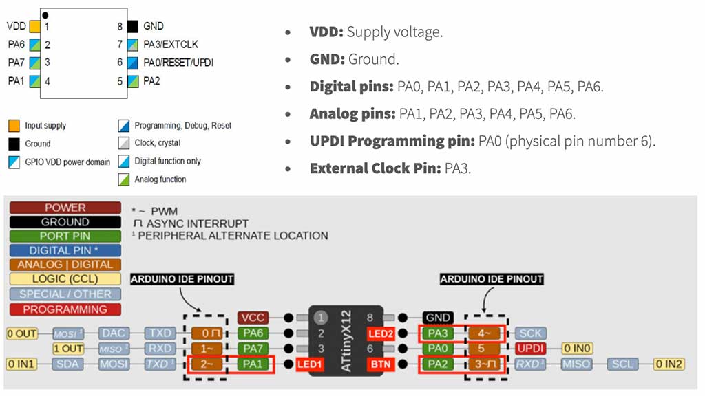
The components i'm going the use are the following:
- ATtiny412 Microcontroller
- Cap 10uF
- Button
- LED Red
- Resistor 499 Ohm
- Connector 1x03 2.54mm Horizontal
We will be using 1206 and 2.54mm size.
All the components are going to be SMD. SMD means Surface Mount Technology refers to components that are placed on the surface of the PCB.
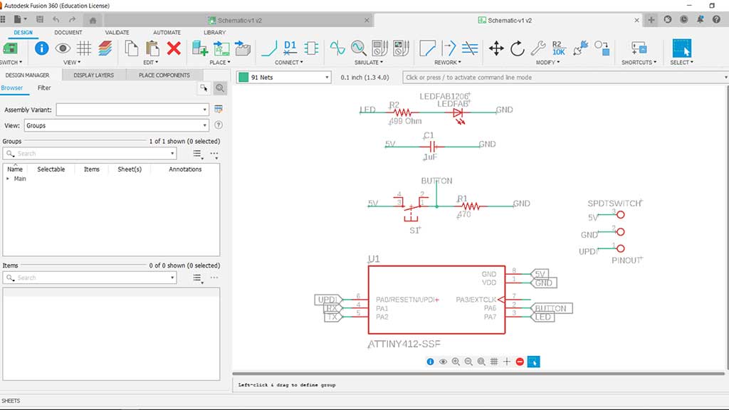
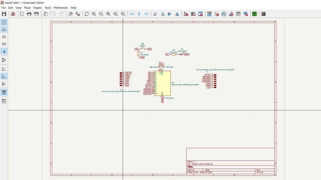
After listing the components and finding them in the library, I added them all to the schematic and after creating the connections.
How to know what the resistance value is without going to a site: The first two or three digits indicate the numerical resistance value of the resistor and the last digit gives a multiplier. The number of the last digit indicates the power of ten by which to multiply the given resistor value.
450 = 45 Ohms x 100 and that means 45 Ohms
273 = 27 Ohm x 103 is 27,000 Ohm (27 kΩ)
7992 = 799 Ohm x 102 is 79,900 Ohm (79.9 k Ohm)
1733 = 173 Ohm x 103 is 173,000 Ohm (173 k Ohm)
Thanks Nuria for explaining this to me!
I'm using labels to indicate the connections. I think it's easier this way.
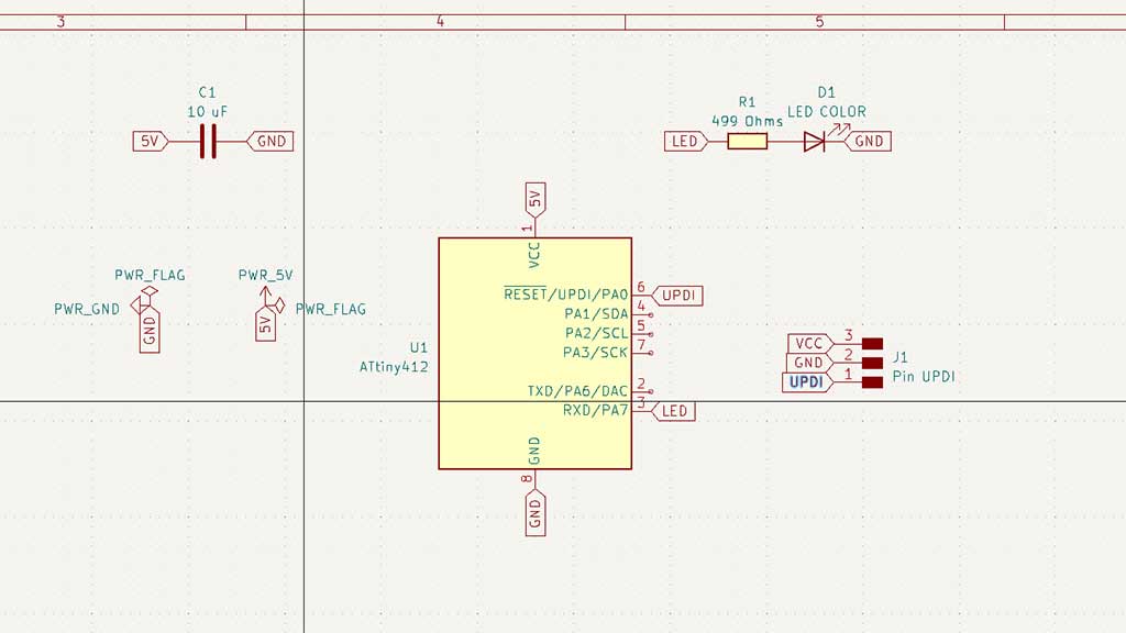
This first schematic does not have a button yet.
After adding the button I had to add a resistor to the button. I used the 499 Ohm resistor. This is called a pull-down resistor
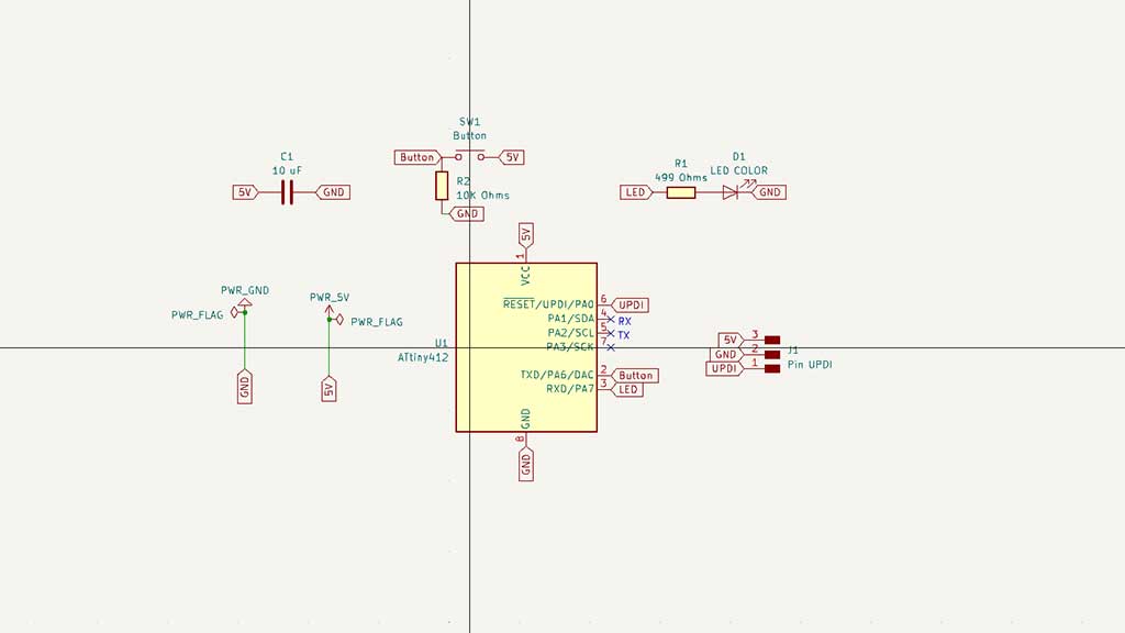
Pull up is to determine an uncertain signal to a high level with a resistor, and the resistor also acts as a current limiter.
Pull down means to clamp the uncertain signal to a low level through a resistor.
It's easier to implement the pull-down.
The reason to use a pull-down is that they can prevent the transistor from malfunctioning due to the influence of noise signals, making the circuit more reliable.
With the schematic ready I clicked the Inspect > Electrical Rules Checker. Everything was good except for some warnings.
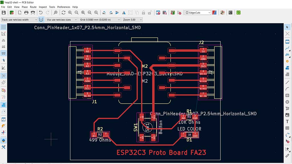
I clicked the "Open PCB in board editor" button to create the PCB.
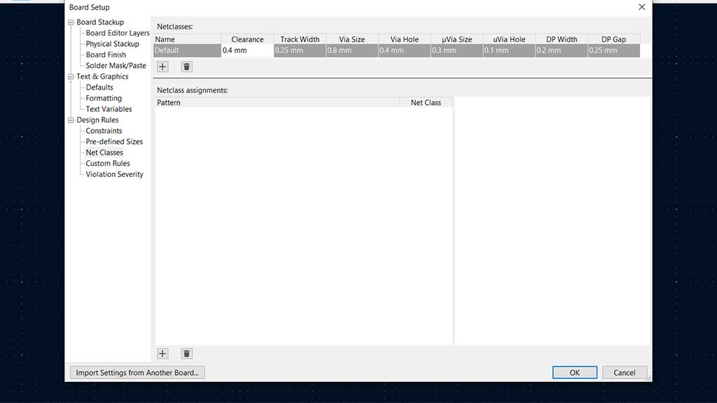
First we need to define the clearance of the traces.
I'm using two sizes: 0.8mm for VCC/5V and 0.4mm for everything else.
The 0.8mm trace should be used not just on the 5V/3V3 but also for motors on anything more "demanding".
I also defined the "predefined" sizes.
After that I placed the components and tried to find the best configuration, clicking on M on the keyboard to move a component and R to rotate it.
After placing the components I connected them.
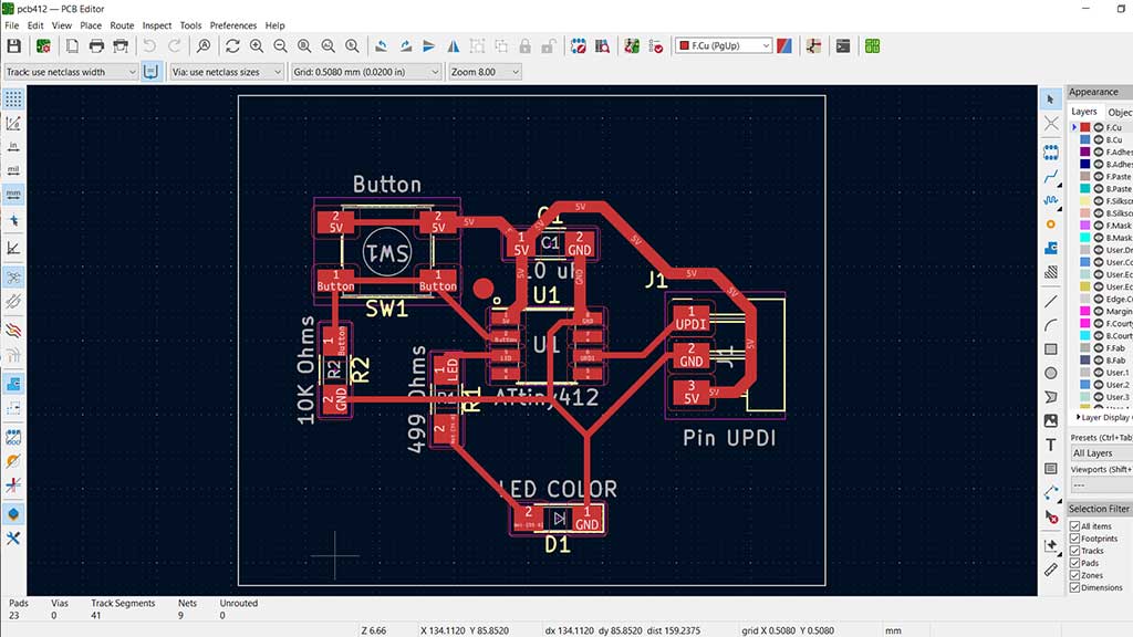
With every component and traces (bus) placed and connected it was time to export the file.
But first I
added a rectangle behind all the components and define its appearance to "edge cut".
At this point I ran the Design Rules Checker. Everything was good.
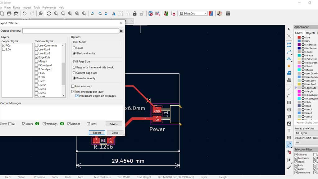
Lastly I finally exported the files using File > Export > SVG.
This action produced two files that I opened in Photoshop (could have been in GIMP) as the process is the same.
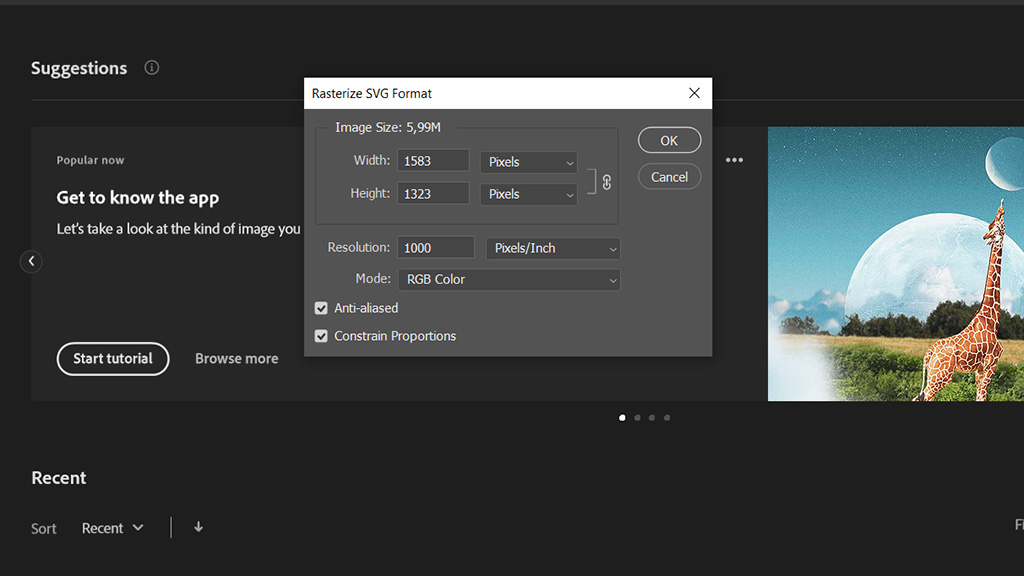
One thing to keep in mind in this process is that in Photoshop the resolution should be 1000 pixels/inch or pixels/mm
Here are the files that were exported:
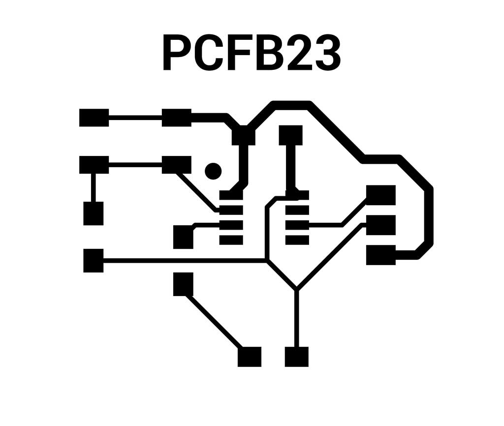

I added a padding of 100px around both images and painted the background white.
For the CNC router the colors need to be inverted.
I could just invert the colors in Photoshop or GIMP but decided to use MODS CE to try it out.
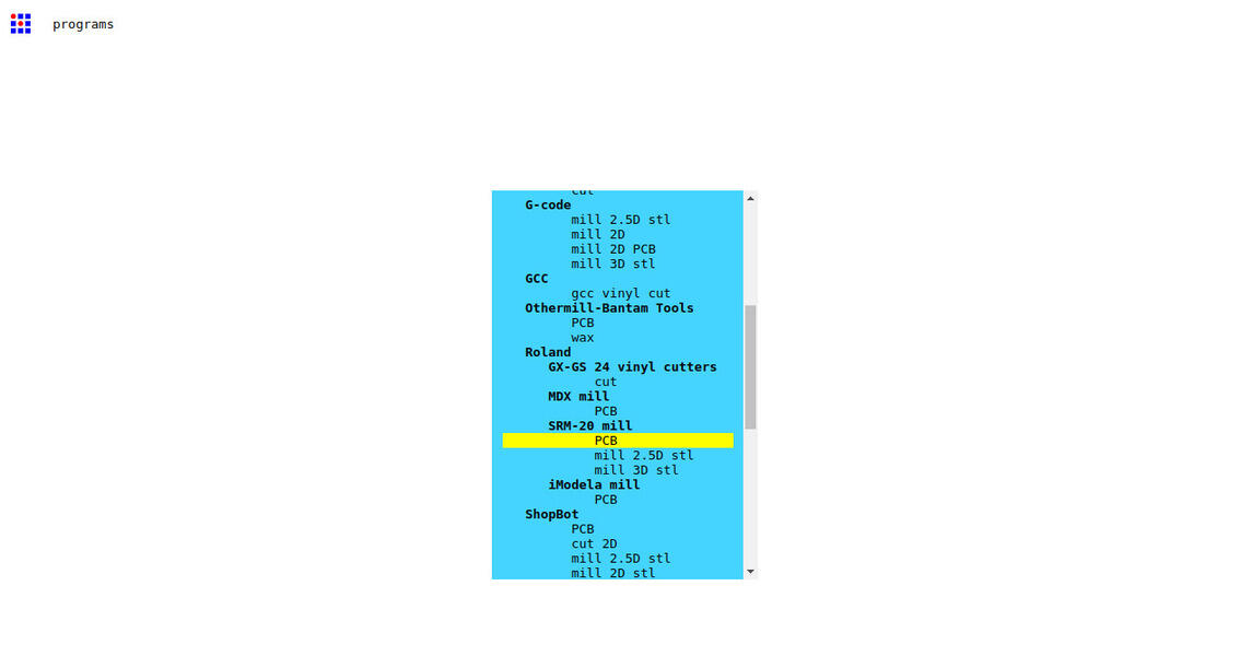
First I clicked with the right button and selected program and then CNC. After that I uploaded the file and followed the process.
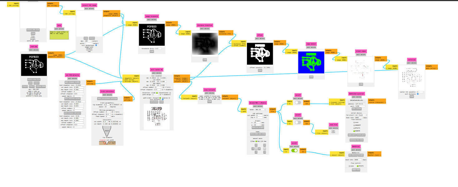
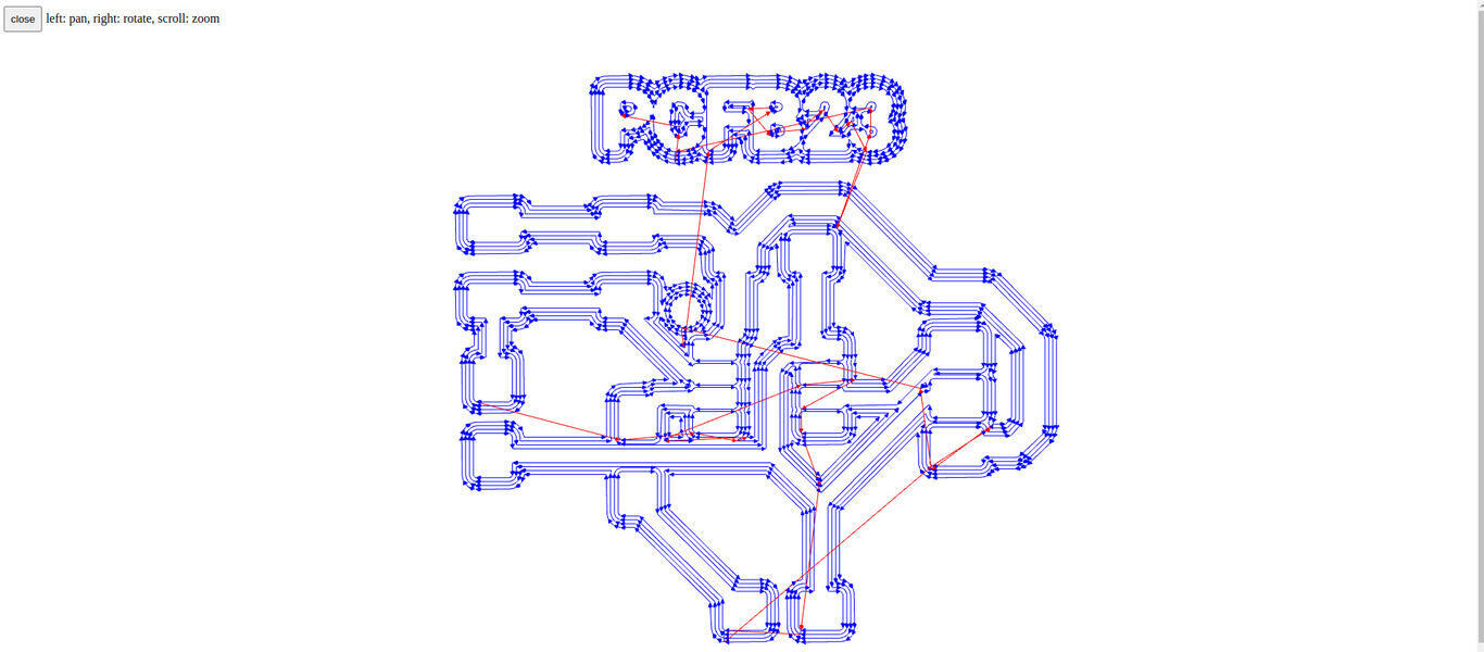
The end result is the CNC file paths.
After finishing I remembered that I should design a board that it's not just rectangular, so i design a
shell in Illustrator and exported it do SVG.
This SVG will be used for the cutting of the board.


This time I decided to invert in GIMP just because.

Now I did everything again...but in Eagle
I wanted to try Eagle as I have been using Fusion 360 for my final project and thought that it would be easier to keep it all in the same software.
First I created a new project and added the Fab library.
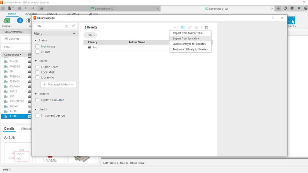
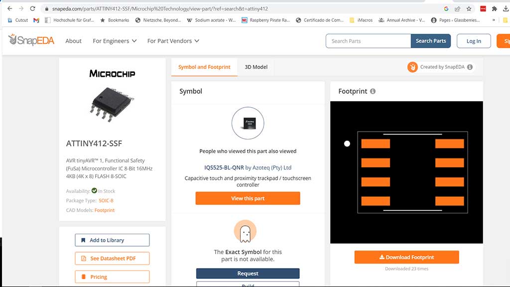
But I didn't find the ATtiny412, so I went to the SnapEDA website and got it from there and imported it.
The import process is the same for the Fusion 360 Fab library.
After having all the components, I went ahead and created the schematic.
After all this was done and the inspector for Electrical rules checker only came back with a few warnings I decided to try out the PCB sketch.
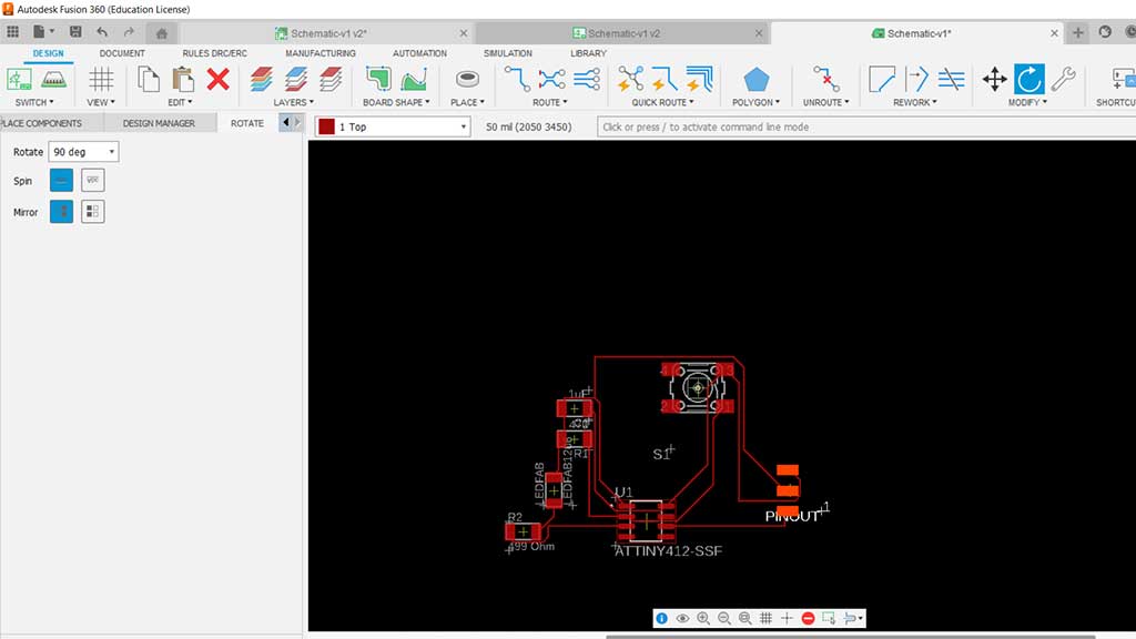
I haven't really figured out the best way to route. I think I just need practice.
It's pretty much the same board, but done in a different software.
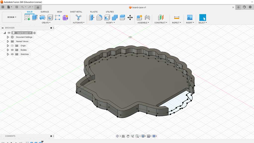
For extra credit I designed a simple case: It was done in Fusion
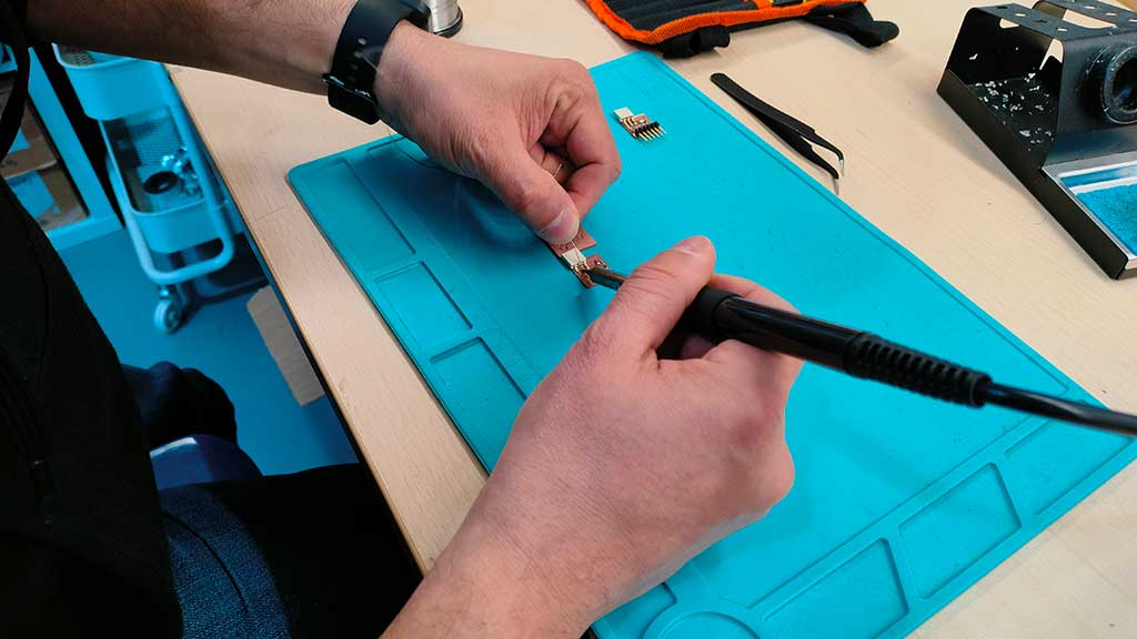
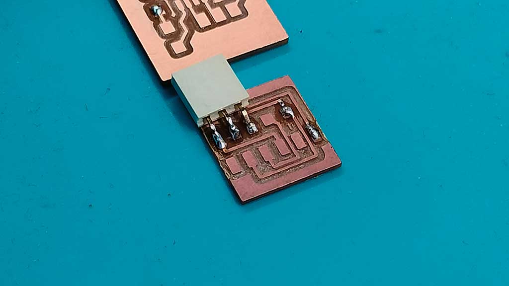
Lastly, Luis had a PCB that I could use to learn and practice soldering. The soldering didn't come out to bad.
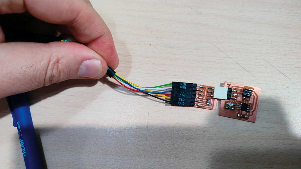
Then i used the programmer I had just soldered to program an ATtiny412 board and make the led blink
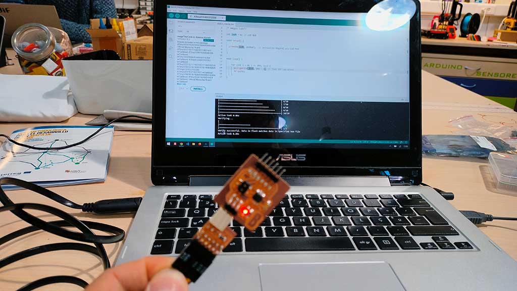

For the final project
As a step in my final project I designed a PCB that would allow me to change between the XIAO RP2040 and the XIAO ESP32C3 as well as allow me to prototype and test sensors.
What I'm trying to do is design a board very much like Fab XIAO, but because I'm not sure which XIAO i'm going to use, I want to be able to switch them.
The board design was made in KICAD.
Files
- ATtiny412 Footprint and schematic Library from Snapeda
- Board case for PCB412, version 1, STEP File
- Board Case V1, STL File
- Shell SVG used for contour cut of the board
- PCB412 Contour cut
- PCB412 Kicad PCB file
- PCB412 Kicad Project file
- PCB412 dsn file
- PCB412 traces
- PCB412 Kicad prl File
- PCB412 schematic file
Learned this week (in no special order)
- How to design a PCB board;
- A lot of technical terms and meanings in electronics;
- Started learning how to use Kicad and Eagle;
- About pull-up and pull-down resistors;
- How to solder small components;
- How to use a logic analyser;
- How to use an oscilloscope;
- How to use a voltmeter;
- How led's work;
- That the lead wire in a LED is the negative and the LED will usually display a flat part on the negative side.
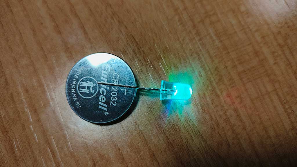
Luis also teached me that the LEDshave two different lead's a bigger one and a smaller one.
The small one if the negative one and the LED itself has a flat part on the negative side. Here is a
photo of an experiment we did with a small battery and adding a LED in the middle, with the positive LED
in the positive side of the battery and the short, negative LED in the negative side of the battery.
Notes and Thoughts
This week was the hardest until now. I had a bit of a problem conjugating my freelance work and assignments, so I got very little sleep.
I don't fully understand a lot of concepts of electronics so I navigating this as a programmer usually does in the start of a project: just look at whats important.
Eagle is not really working out for me, but I hope it will click really soon has I have the 3D model of the shell in Fusion360 and it would be cool to just do the design part of the project in one tool;
Links
- Adrián Torres Fab Academy site
- Voltage, current, resistance and Ohms law.
- What is Voltage?
- Fab Eagle library
- Fab Kicad Library
- Online Conversion Calculators
- Online Conversion Calculator Capacitance
- Conversion Calculator Surface Mount resistor code
- How to use and read a Multimeter and a Oscilloscope (in Spanish)
- Osciloscope Basics
- Saleae Logic 2 Software
Glossary:
- Ohm: The unit of electrical resistance, measured in ohms (Ω).
- Ohms Law definition:Ohm's law states that the current through a conductor between two points is directly proportional to the potential difference across the two points. Introducing the constant of proportionality, the resistance, one arrives at the usual mathematical expression for Ohm's law.
- Ohm's law formula: V = IR
- Ohm's law equation: V = I x R
- V = Voltage: The difference in electric potential (charge) between two points, measured in volts (V).
- I = Current: The rate of flow of charge, measured in amperes (A).
- R = Resistance: The opposition to the flow of electric current, measured in ohms (Ω).
- Power: The rate at which electric energy is converted into another form, measured in watts (W). It relates to Voltage and Current.
- Power = Voltage x I (current)
- Current: The rate of flow of charge, measured in amperes (A).
- Ampere, Volt and Watt: The unit of electric power, measured in Amperes, Volts of Watts (W).
- Resistor: A passive two-terminal electrical component that implements electrical resistance as a circuit element. It works as sunglasses. Light does come throught, just not all of it.
- Capacitor: A passive two-terminal electrical component that stores electrical energy in an electric field. It's like a "battery".
- LED/Diode: A two-terminal electronic component that conducts primarily in one direction (asymmetric
conductance).
A LED is a diode. Diode's have a positive and negative side. That's called a anode and a cathode. - Transistor: A semiconductor device used to amplify or switch electronic signals and electrical power. For example for multiple LEDsa microcontroller may not be able to power them all so insted it controls transitors that add the allow a bigger current to flow to the led directly from the power source.
- Microcontroller: A small computer on a single integrated circuit containing a processor core, memory, and programmable input/output peripherals.
- Integrated circuit: A set of electronic circuits on one small plate (chip) of semiconductor material. It's not a microprocessor. That calculates, a microcontroller can calculate but also communicate.
- Logic gate: An electronic circuit having two or more input lines and one or more output lines. It
- Oscilloscope: An electronic test instrument that allows observation of constantly varying signal voltages, usually as a two-dimensional graph of one or more signals as a function of time.
- Multimeter: An electronic test instrument that measures voltage, current and resistance. It can also test continuity.
- Logic analyser: An electronic test instrument that allows observation of constantly varying signal voltages, usually as a two-dimensional graph of one or more signals as a function of time.
- Voltmeter: An electronic test instrument that measures voltage.
- Amperemeter: An electronic test instrument that measures current.
- Ohmmeter: An electronic test instrument that measures resistance.
- Logic level: A logic level is the voltage level at which a digital circuit, or digital signal, either works or does not work. For example, the voltage level of a digital signal may be either high or low. In a digital circuit, the logic levels are typically represented by two different voltage levels, such as 0 V or 5 V. The logic level of a digital signal is the voltage level at which the signal is considered to be either high or low.
- Logic level high: The logic level high is the voltage at which a digital circuit, or digital signal, works. For example, the logic level high of a digital signal may be 5 V. In a digital circuit, the logic levels are typically represented by two different voltage levels, such as 0 V or 5 V. The logic level of a digital signal is the voltage level at which the signal is considered to be either high or low.
- Logic level low: The logic level low is the voltage at which a digital circuit, or digital signal, does not work. For example, the logic level low of a digital signal may be 0 V. In a digital circuit, the logic levels are typically represented by two different voltage levels, such as 0 V or 5 V. The logic level of a digital signal is the voltage level at which the signal is considered to be either high or low.
- Logic level shifter: A logic level shifter is a circuit that is used to change the voltage levels of a digital signal. For example, a logic level shifter can be used to change the voltage levels of a digital signal from 5 V to 3.3 V. Logic level shifters are often used in digital circuits that have different voltage levels. For example, a digital circuit may be designed to use 3.3 V logic levels
Some of these definitions were generated by AI using ChatGTP.