This week's fun assignment was:
Group assignment:- Complete your lab's safety training
- Test runout, alignment, fixturing, speeds, feeds, materials and toolpaths for your machine
- Document your work to the group work page and reflect on your individual page what you learned
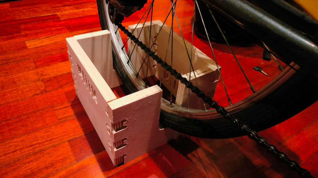
- Make (design+mill+assemble) something big

Computer controlled machining
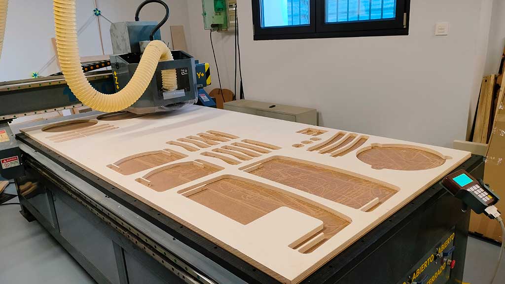
The cutted project
Here is the documentation for this week's assignment.
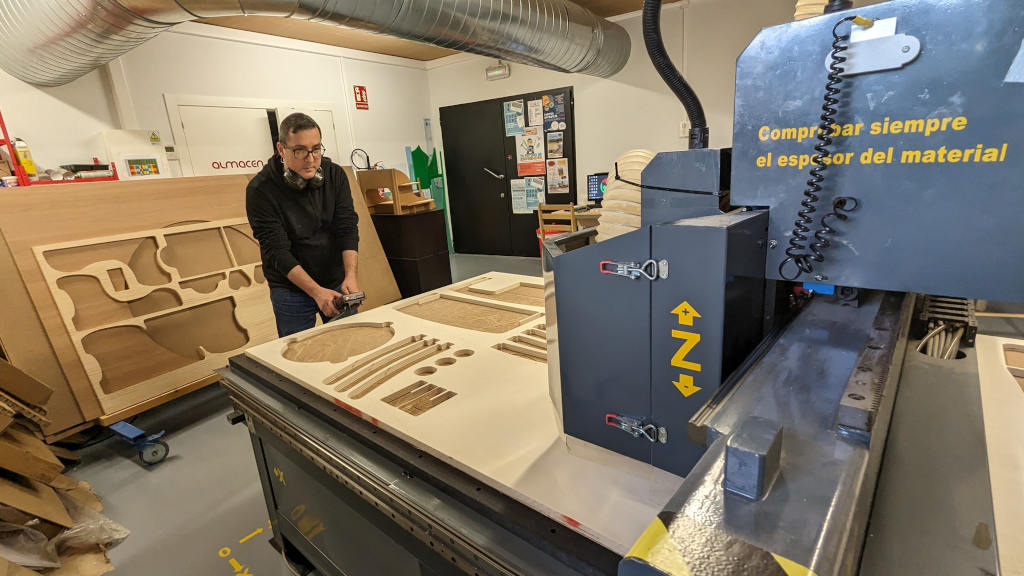
The CNC Machine I will be using for this assignment in Fab Lab León is the following:
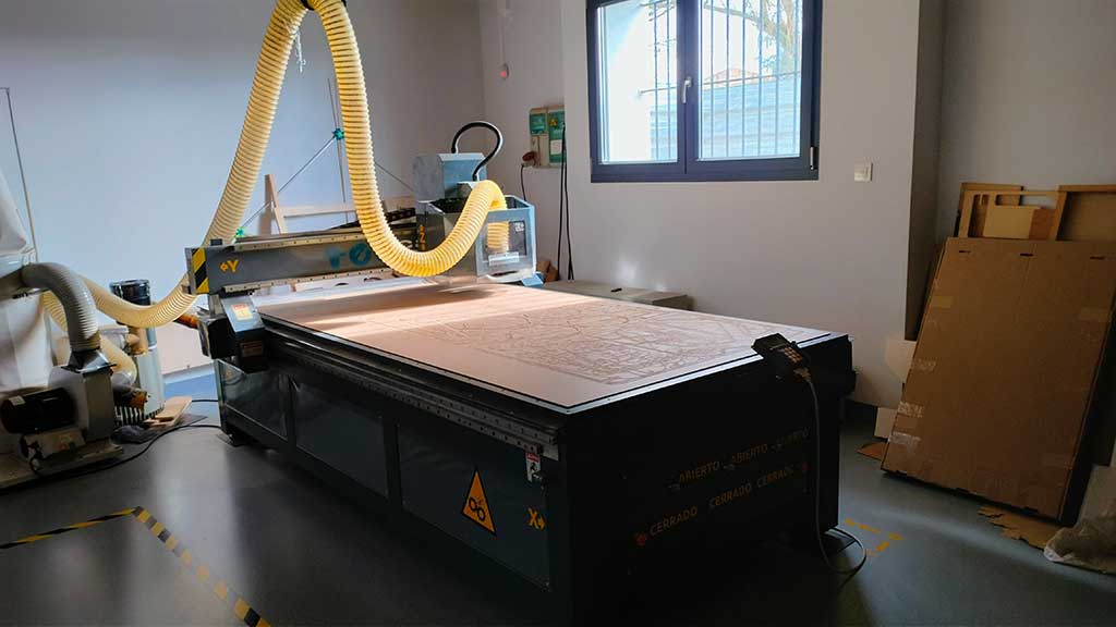
- Milling Machine CNC TEC-CAM 500.
- Software used: Aspire VCarve- https://www.vectric.com/products/aspire
- Dimensions: 1800x3000mm;
- Work area: 1220x2440mm;
- Bridge height: 120mm;
- Maximum thickness of the material: ~ 40 mm (depends on the mill);
- Supported file types: STL, DXF, and others;
- Materials: Methacrylate, MDF, Bakelite, PP, Solid wood, PVC, Brass, Foams;
- Uses a vacuum table.
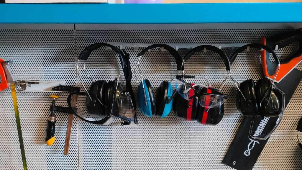
But first, safety:
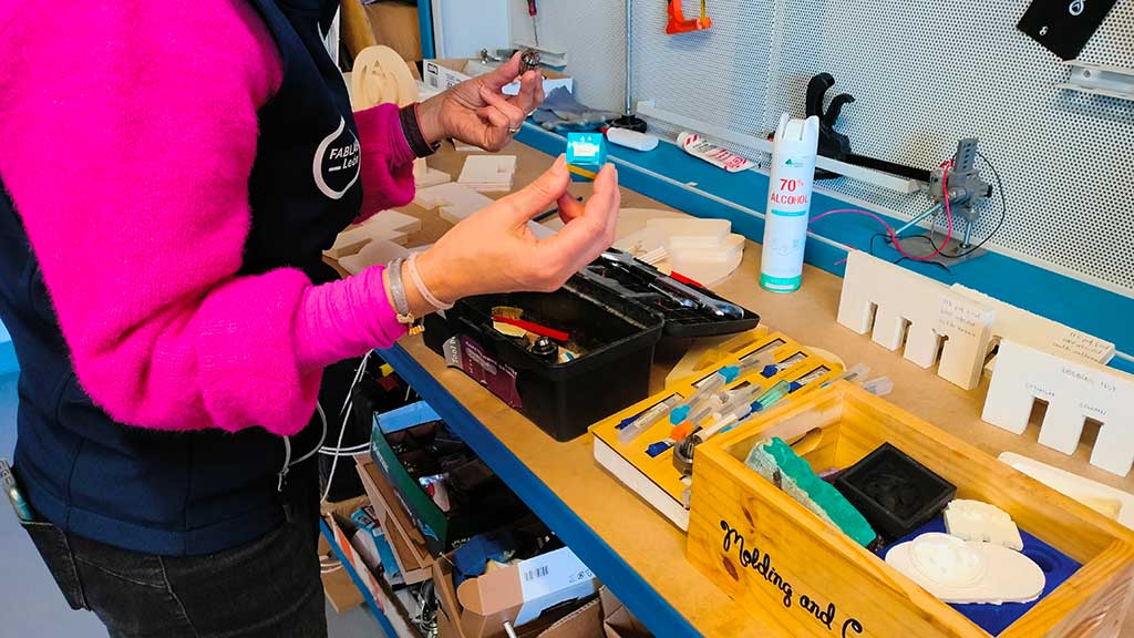
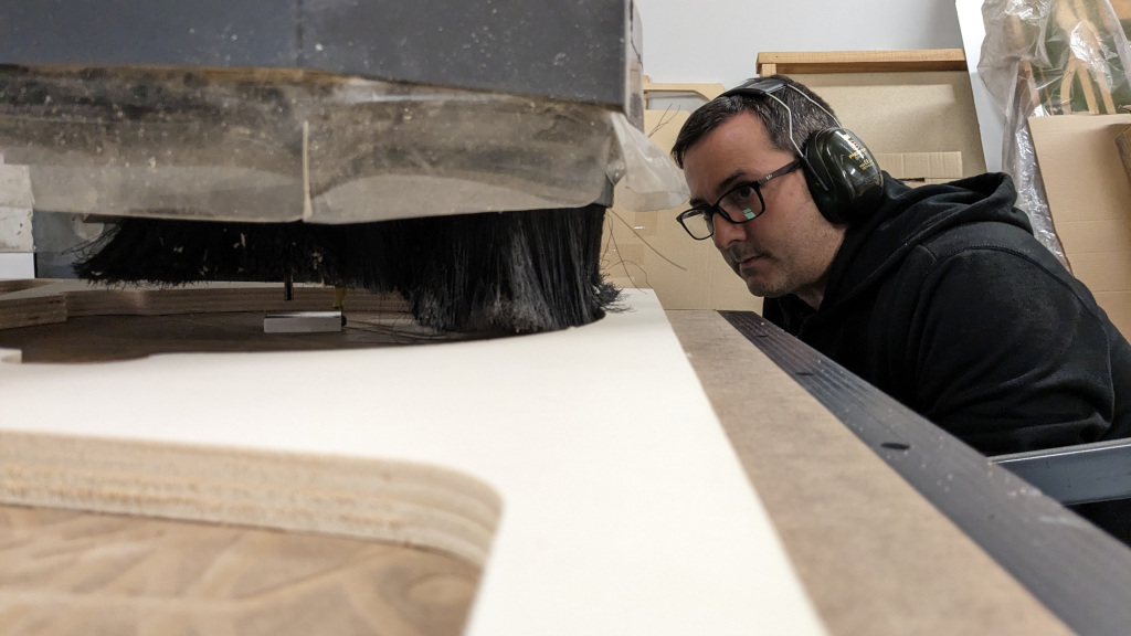
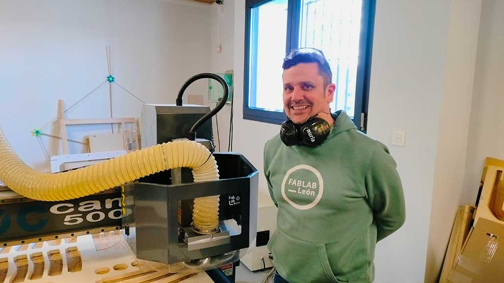
When operating the CNC always use Personal Protective Equipment PPE:
- Earmufs;
- Safety goggles
PRECAUTIONS:
- Remove dangling items: Loose hair and beards, laces, etc;
- Keep a safe distance;
- Machine remote control always in hand ready to stop the machine;
- Make sure to know where the emergency stop button(s) is/are located;
- Only use gloves to handle the material (wood or other) but never when operating the machine.
- Make sure to know where the fire extinguisher is located;
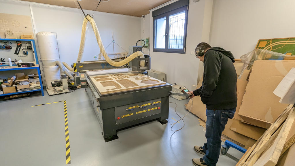
Altought the person operating the machine is closer to the machine itself, the rest of the persons in the room should be behind the line that can be seen in the first image.
Tools
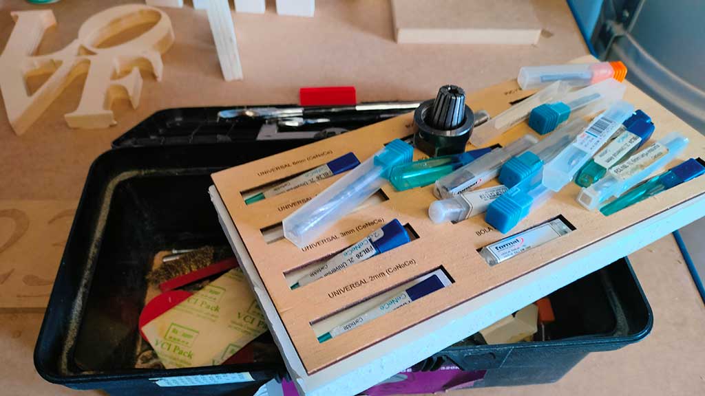
After the safety training we moved on the milling cutters.
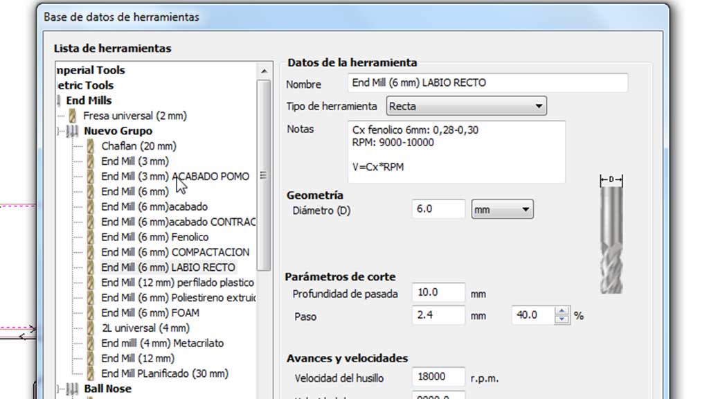
Fab Lab León has a great variety of milling tools:
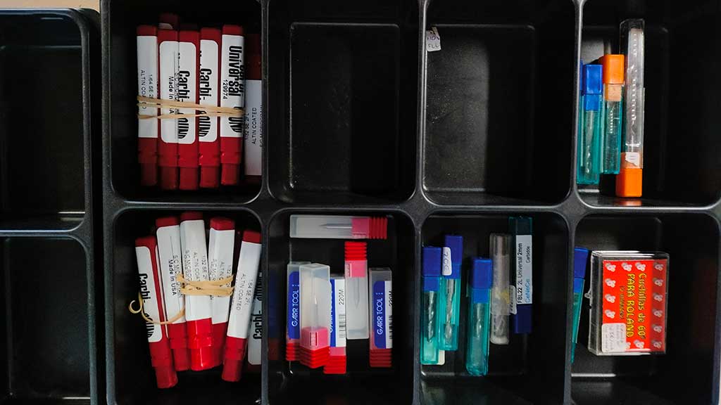
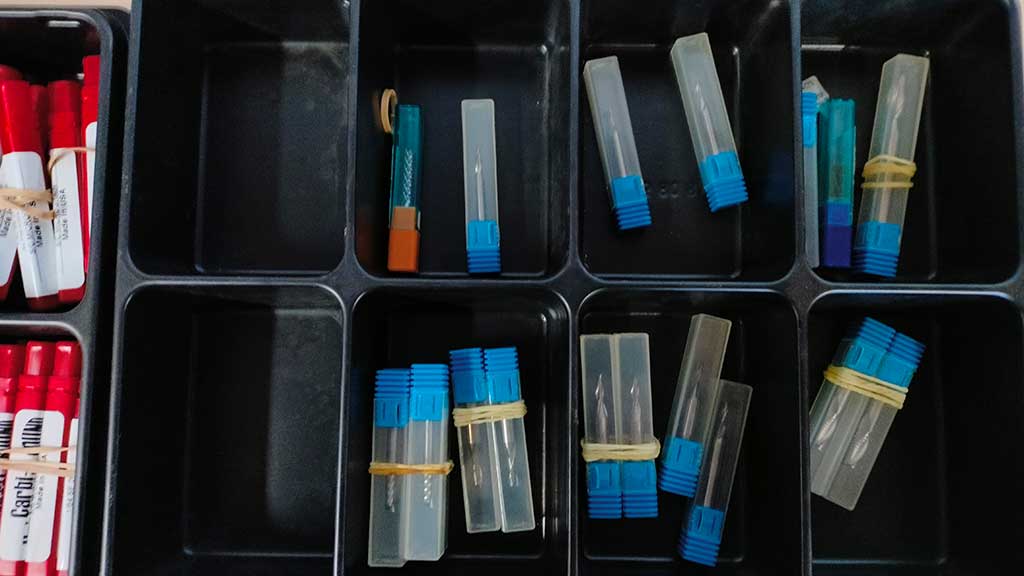
Nuria taught me about the end mills and what they do and where they should be used.
I calculated the Feed rate, but did it just for the exercise as the software used in Fab Lab León has a library of tools with that information:
The formula for the calculations are the following:
Feed rate (mm / min) = Chip load x flute number x RPM
For this calculations I will use a table from Perez Camps, the Machine distribuitor in Spain.
| Diameter | Hard wood | Plywood | MDF |
| 3 | 0,08 - 0,13 | 0,10 - 0,15 | 0,10 - 0,18 |
| 6 | 0,23 - 0,28 | 0,28 - 0,33 | 0,33 - 0,41 |
| 10 | 0,38 - 0,46 | 0,43 - 0,51 | 0,51 - 0,58 |
| 12 | 0,48 - 0,53 | 0,53 - 0,58 | 0,64 - 0,69 |
And has the image above indicates, I will be using the 6mm Flat two flute mill.
So the values will be:
0.28 x 2 x 18.000 = 10.080 mm/min
0.33 x 2 x 18.000 = 11.880 mm/min
I will have to check this values with my instructors to make sure that i'm using the correct settings.
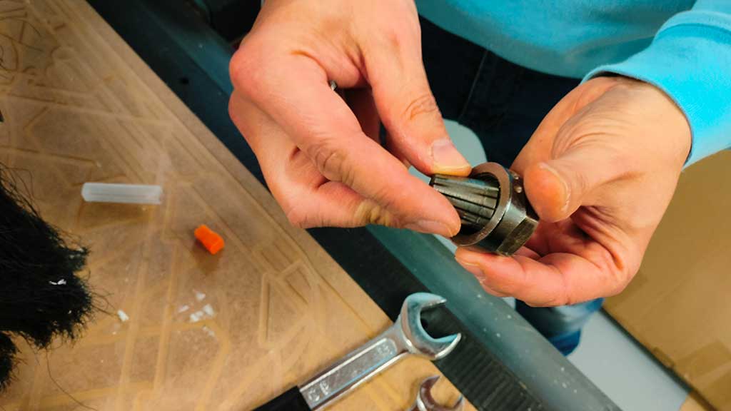
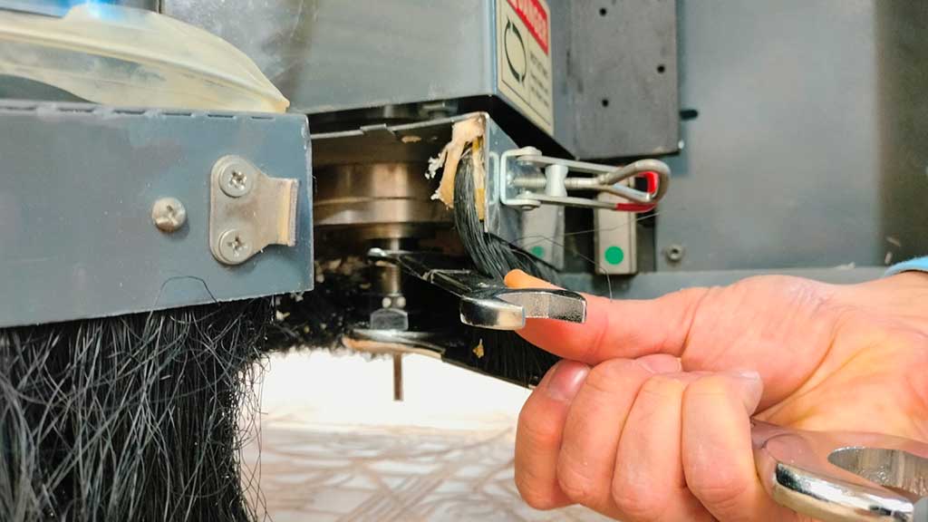
One of the most important parts of all this milling process is to know how to correctly set up a end mill inside the collet.
First Nuria explained how to clean the interior of the collet. This is important has different materials can leave dust of residue.
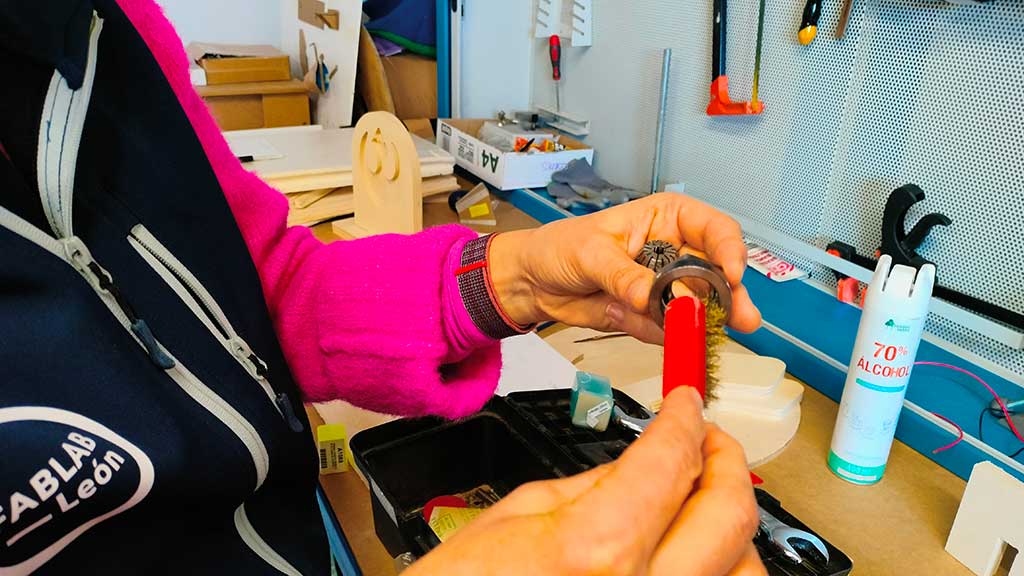
This maintenance is done with a small copper brush
Nuria also showed me a Spindle motor with the collet and the refrigeration system.
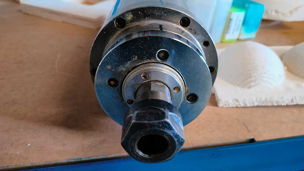
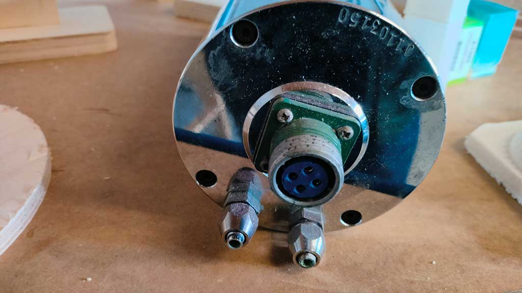
This model is water cooled and the water used must be distiled water as tap water will produced the algae.
First the collect must be screwed by hand but not too tighly. Spining the spindle is a faster way to screw the part.
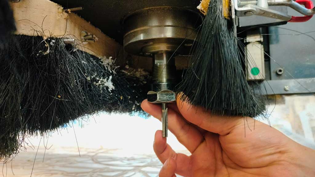
After that the collet must be tighly tighen and there is a special way to it.
The tools needed are two flat wrenches, 21 and 30 mm.
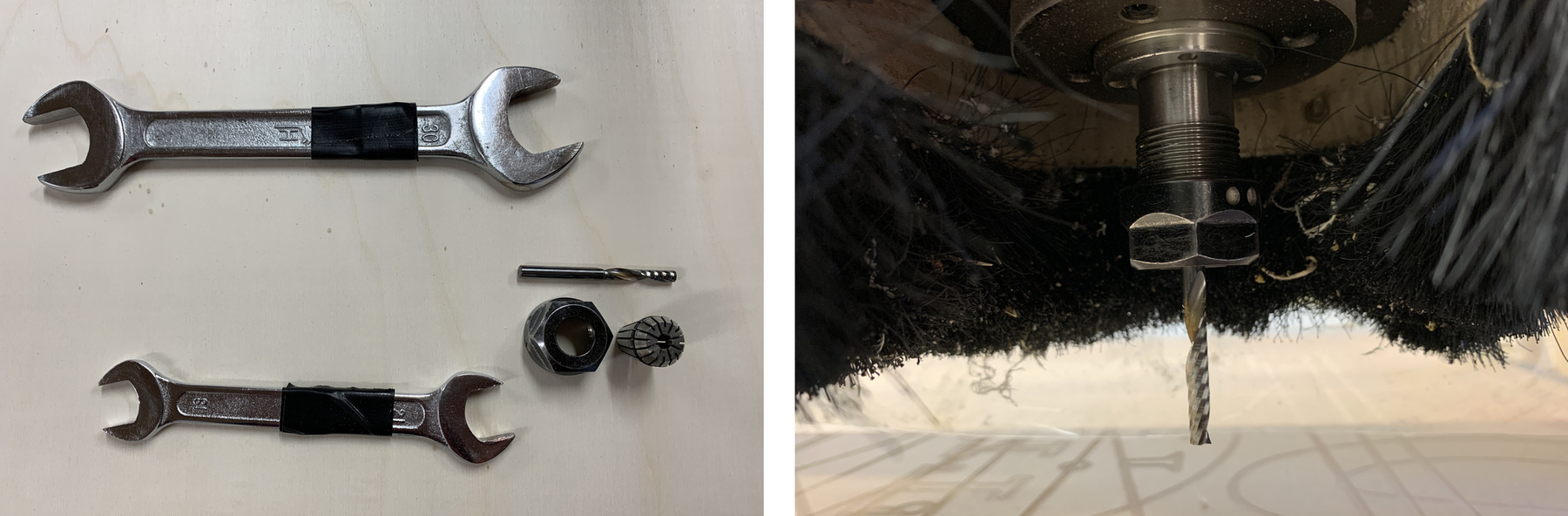
The black tape indicates the side of the wrench to use.
First the two wrenches are used one in each hand and in each part, the spindle and the collet.
Around 5 mm of stem of the end mill must be visible before the flutes.
When it's tight without forcing the parts, we need to change the way we handle the tools. We will be using both
tools in just one hand.
This method will prevent the end mill on the sleeve from being too tight.
Now that the end mill is inserted we can measure the material.
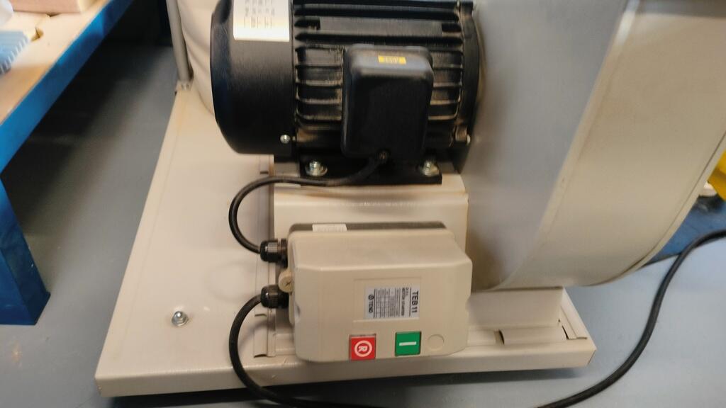
But we have to turn on the machine first!
This is where we turn the CNC ON, also it's where we turn the vacuum system on.
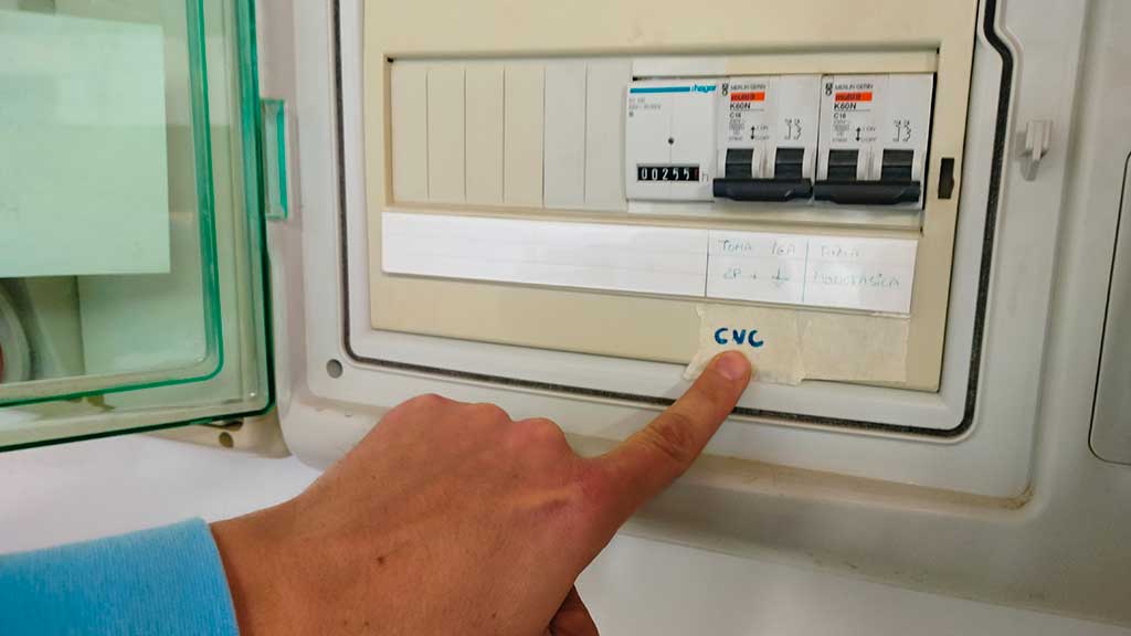
But more importantly...This is where we turn off everything.
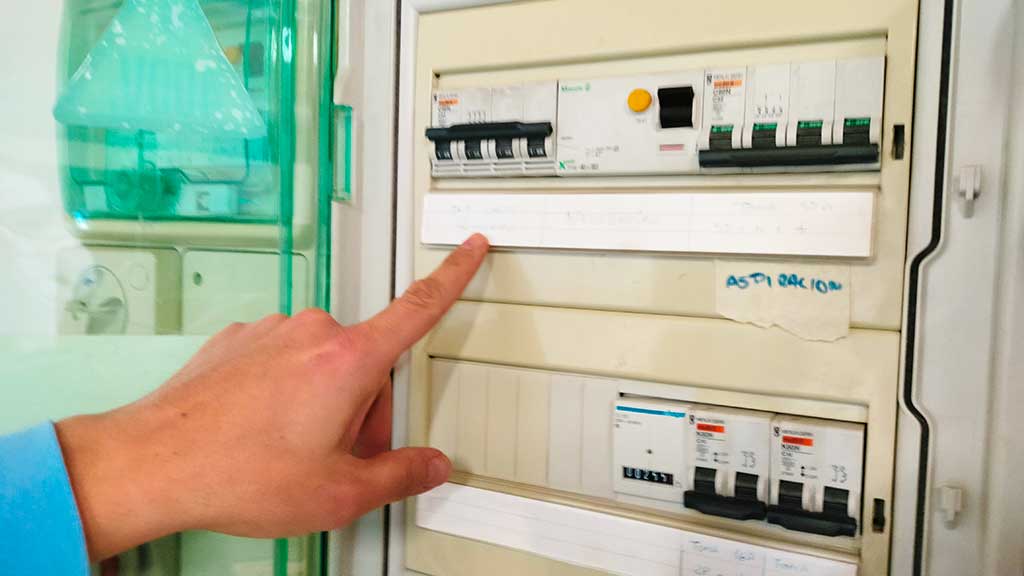
Also, keep in the mind that there are emergency stop buttons on the "front" of the machine.
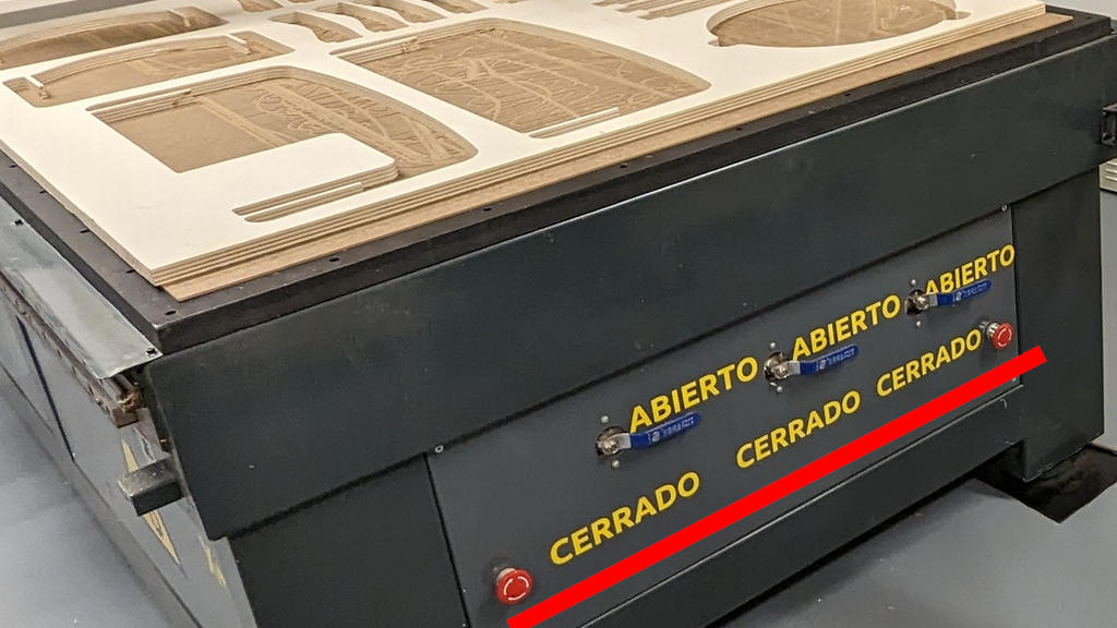
The table vacuum is what keeps the material in place. It's a very powerful and noisy part of the machine that sucks the air with such force that the material doesn't move from the table even if pushed.
It's a great system because not only can it be configured in specific zones of the work area but also because we don't need other fixtures to use it.
Individual assignment
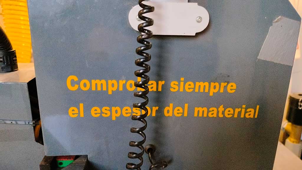
Measuring the material
I need to measure the material 4 times.
Without the vacuum system
1. From the sacrificial board;
I also set XY = 0. with the button XY->0.
2. From the Material;
With the vacuum system on
1. From the sacrificial board;
2. From the Material;
With these values we can just subtract one value from the other and get the material height with and without the vacuum system.
This is important because the vacuum system is so powerful that the material has less height when subject to the vacuum.
To measure we use the Z-Probe.
It's a piece of metal that's connected to the machine and when the end mill touch it, it closes the circuit and calculates the height from the defined zero.
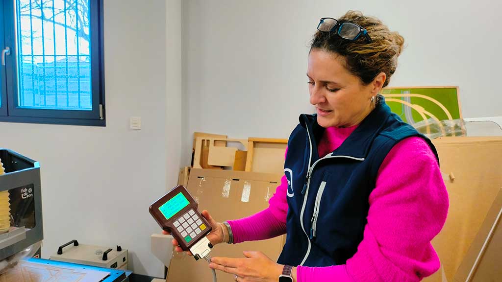
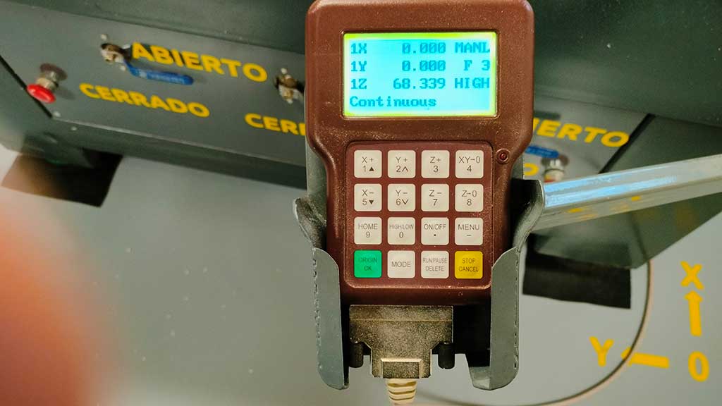
Using the remote we place the spindle over the z-probe.
Then we press the button to measure the height.
We press the button MENU on the remote control first, and without releasing the MENU, we press the ON / OFF button and then release both simultaneously. The spindle will start slowly descending until it touches the probe. After that it will rise again.
You can hear it without the vacuum but with the vacuum you can't and the spindle is so fast that's it's hard to see if it's spinning.
BE EXTRA CAREFULL DOING THIS!
Take note of the value as it will be needed later on.
We will now repeat this operation again but over the material and do it two more times with the vacuum system ON.
I forgot to mention that the material should be placed and align as best as possible to the rubber where it lays.
After this is done we "zero" the machine. This sets the XY axis to 0. That means we place the spindle where the machine will start running and press the XY->0 on the remote.
The material height was:
Without vacuum system: 83.778-64.991=18.787mm;
With vacuum system: 84.004-65.944=18.060mm;
So the material height is 18.060mm with the vacuum system, but Pablo who has a lot of experience with
this tells me to add some margin to the value.
I considered 18.887 and 18.160. It's a really small difference.
Now we can start preparing the files to cut.
Some consideration.
- The design can be done in any vector design software, but as I will learn, just keep to something that allows parametric design.
- The file format to export should be DXF.
- Make sure that your design takes into account the diameter of the end mill. If you have a line, that will be the diameter of the end mill.
- Make sure that the vectors are joined!
- The part zero is different from the zero of the machine;
- XY origin position: bottom left;
- X and Y zero is from the surface of the material;
I design my project in Adobe Illustrator.
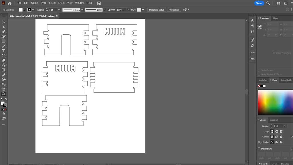
This was my first mistake, designing in Illustrator.
It's not parametric software, so I had to do a lot of manual work to make it work.
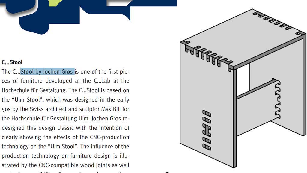
I wanted to use a press fit and had looked up the 50 Digital Joints book.
I found the Stool by Jochen Gros interesting and decided that I could try to design something
similar integrating the bike parking part.
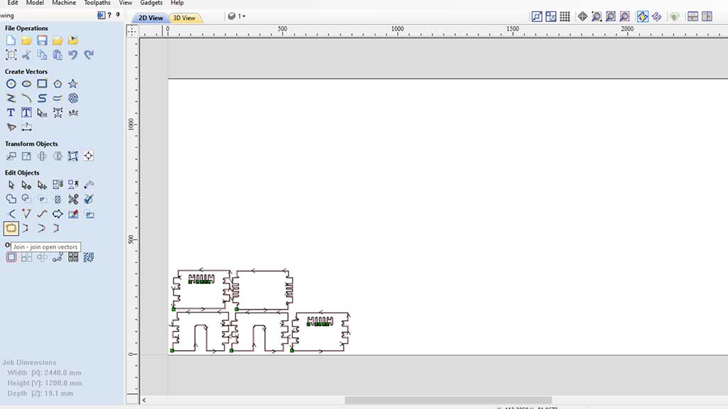
The first problem with my illustrator file started with the export part.
The best way to open a file in Aspire is to import it, as that way it does not bring the "background" with it.
The background is the settings for the machine size.
Another reason is that by importing we don't need to reset the machine to Zero. We can just keep adding parts knowing what the last cutted part was and where.
To import a file to Aspire we need it to be in DXF format, but because the CNC machine and the software, although they work really well, are nowhere new, the export in illustrator must be done using the DXF 2009 version.
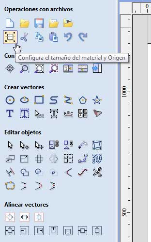
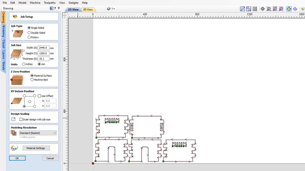
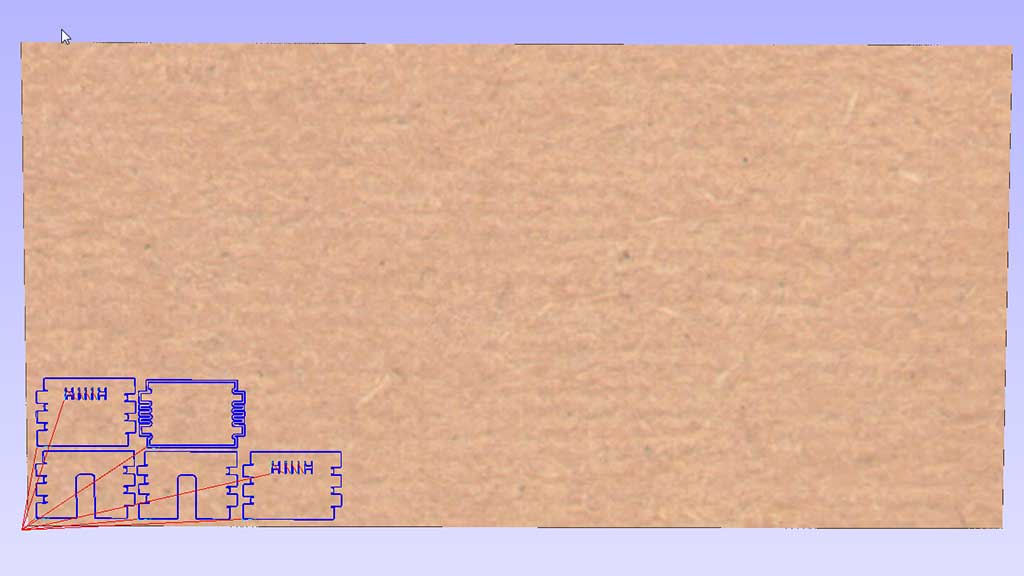
So first we open Aspire and define the size of the material by clicking the define size of origin material:
After that we must import the DXF file and close all the vectors that may open.
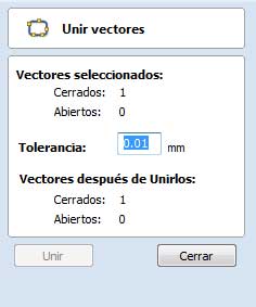
There's a trick here. First we select all the items and click the close buttons, but after that we must repeat one item at a time.
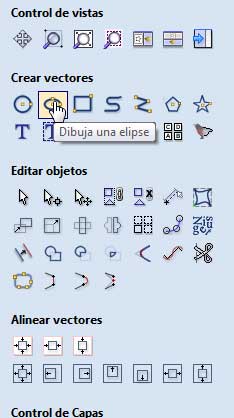
Aspire does come with some simple vector drawing tools that can come in handy.
After this we must configure where the zero of the material is and how everything is going to work.
Next we must create the toolpaths:
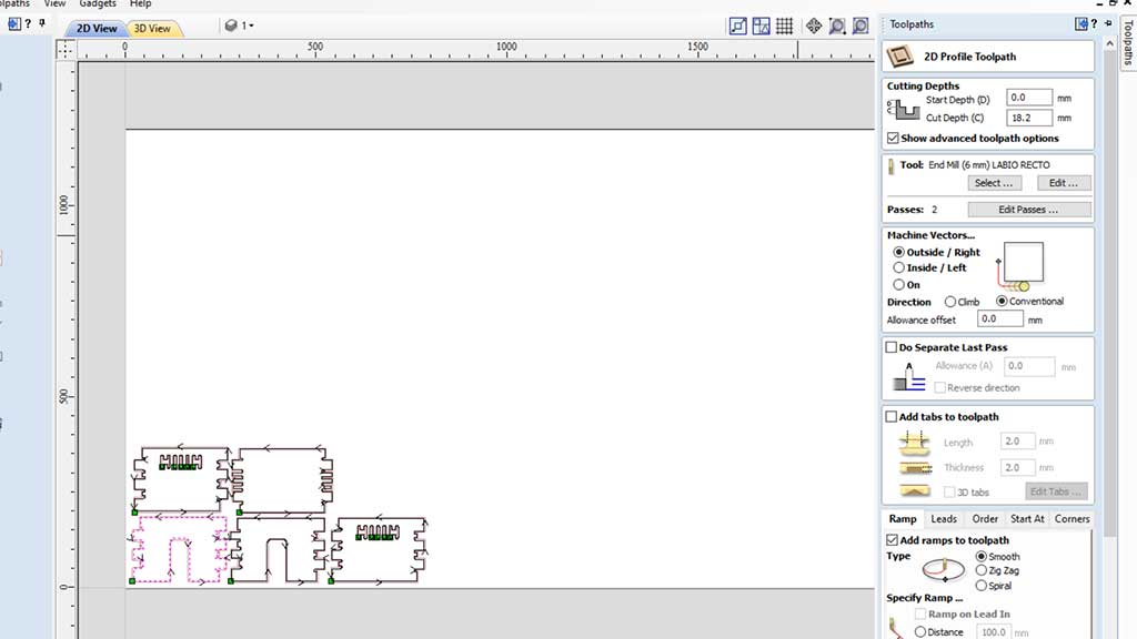
In the cut depth we use the value of the height of the material we calculated earlier.
We must also define if it's an exterior cut or an interior cut depending on what we are cutting.
We must also configure the "ramp" and its settings.
After all this is done we must save the toolpaths.
Now we must add a name to each Toolpath. The name should be something like 3 Letters, INT (for interior) or EXT (for exterior) and the version.
After this we must click on calculate and if everything goes right, just click done/close.
This will calculate the paths.
After all the toolpaths are configured we can save them on our computer before copying them to the USB drive we are going to use.
The file format to save is the Gcode (mm) Tap and we should not erase from the USB, just add files with different names.
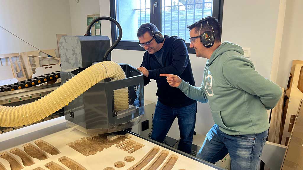
Let's start cutting
We insert the USB pen drive into the remote control and put our earmuffs and our safety glasses on and turn the table vacuum system.
Before starting we must make sure that the machine is ready and that the spindle enclosure is closed.
Starting:
To start cutting we must press the RUN/DELETE button, choose U DISK and then the file that we want to cut and then press OK two times.
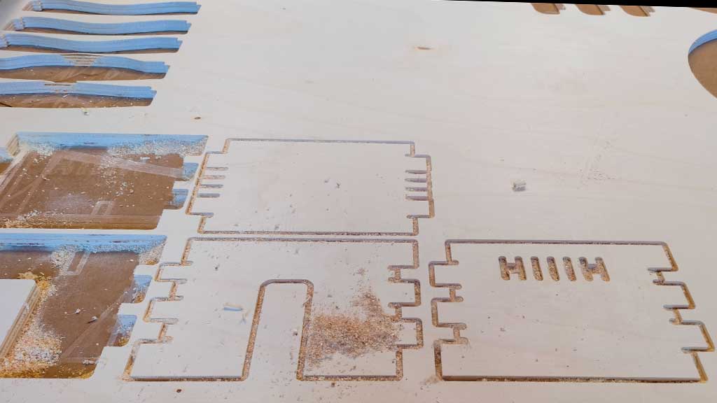
We first cutted only the first two parts to test the joints.
We also have to turn on the chip vacuum ON
The CNC is much faster machine than what I initially thought.
The joints work well, it has a tight fit.
I didn't take into account that there is a difference of height in boards in Europe from elsewhere.
I used the examples from the book 50 Digital joints, but they use boards with 16mm and not 18mm.
Because I decided to do this in illustrator, all changes now are going to be pretty hard.
>I decided to switch to Fusion 360 and do a parametric design.
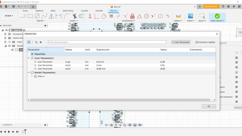
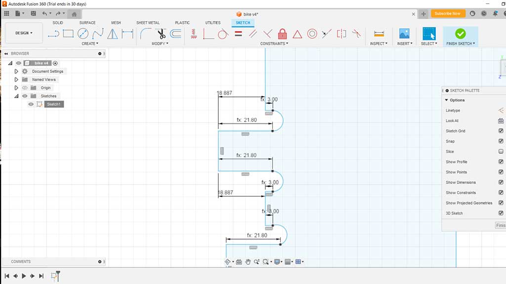
Now I can change the parameters and the design will change accordingly.
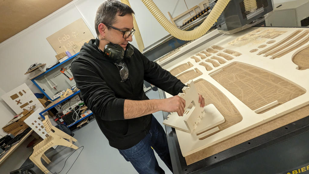
Time to cut the project
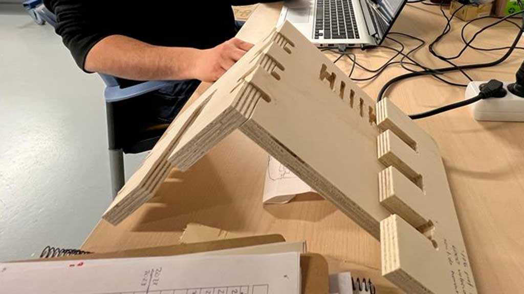
The joints worked pretty well although. Very tight and strong fit.
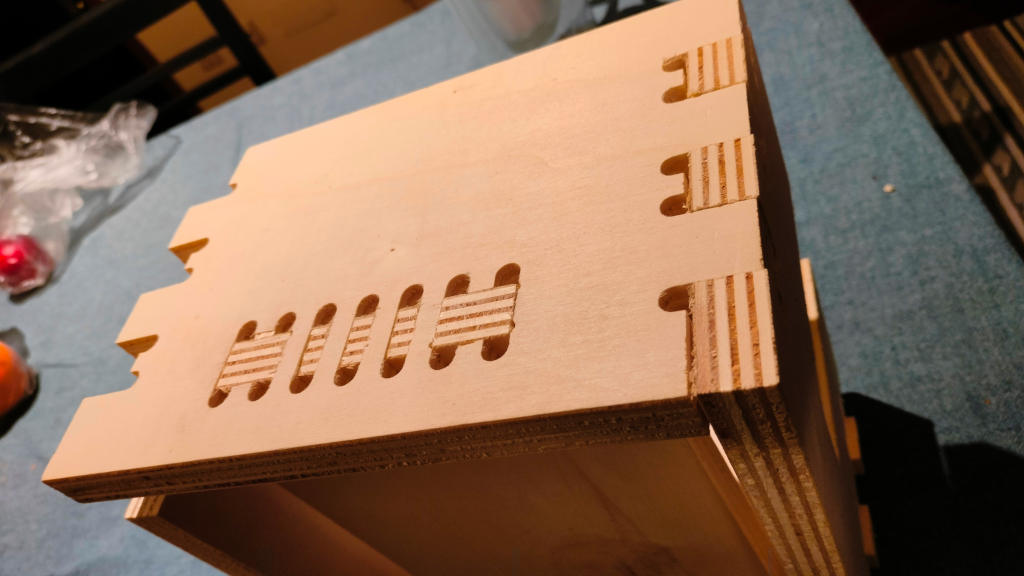
I had to use a hammer to ease the building.
But not everything worked alright. I did a mistake while measuring the support board and it came out too big.
Complete workflow after adding the tool to the spindle and zeroing the machine:
Step 1: Prepare the file:
- 1. Import file;
- 2. Make sure that every vector is closed;
- 3. Select the vector and in the toolpath add a temporary height;
- 4. Select the cutting tool (this must be done every time);
- 5. Select if the cut is inside or outside;
- 6. Select Ramps, add ramps to toolpath, smooth with an angle of 30.0;
- 7. Add a name with 3 digits, if it's a outside or inside cut and the version: 100INTV1;
- 8. Click calculate;
- 9. Click close;
Step 2: Measure the material height with and without the vacuum system:
- 1. First measure just with the sacrificial board;
- 2. Add the Z-Probe under the tool and lower the tool slightly to make sure it will touch the probe;
- 3. In the remote press the MENU button and without letting go press the ON/OFF button letting go of the two simultaneously.
- 4. After measuring, take out the z-probe and put it back in its place;
- 5. Repeat the process with the material;
- 6. Calculate the difference of height to get the material height
Step 3: Finishing the file preparation:
- 1. Go back to the toolpaths and add the correct height;
- 2. To this value add 0.1mm if the material is soft and 0.3mm if it's a hard material;
- 3. Add the tool again!
- 4. Save;
- 5. Select Gcode (mm) Tap;
- 6. Save each toolpath separate;
- 7. Don't delete anything, just add with different file names;
- 8. Eject the USB drive
Step 4: Cutting:
- 1. Add the USB dongle to the remote control;
- 2. Turn on the vacuum systems;
- 3. Press the RUN button:
- 4. Select U DISK;
- 5. Select the file;
- 6. Press OK;
- 7. Press OK again;
- 8. Keep remote in hand;
For the final project
Nothing this week
Files
Learned this week (in no special order)
- How to safely operate a CNC;
- Don't design in Illustrator except for graphic stuff;
- Measure twice and cut once;
Notes and Thoughts
This week didn't go that easily. I had a lot of problems with the files and the way to build the project.
I was a bit afraid to use the machine. I think it would have been easier if we started with the small CNC for electronic boards before using this big one.
Links
Glossary:
- Runout:: The amount of runout in a machine spindle. Runout is the amount of variation in the diameter of the spindle.
- Spindle:: The spindle is the rotating part of a CNC machine that holds the cutting tool. The spindle is powered by a motor and is usually driven by belts or gears.
- Clearance:: The distance between the cutting tool and the workpiece.
- Feedrate:: The speed at which the cutting tool moves across the workpiece.
- Free:: The distance between the cutting tool and the workpiece when the spindle is not cutting.
- Plunge:: The distance the cutting tool moves into the workpiece per revolution of the spindle.
- Toolpath:: The path followed by the cutting tool.
- Workpiece: The material that is being cut.
- Fixture/Fixturing: A fixture is a device used to hold a workpiece in a fixed position while it is being machined.
Some of these definitions were generated by AI using ChatGTP.