This week's fun assignment was:
Group assignment:
- Compare as many tool options as possible.
- Document your work on the group work page and reflect on your individual page what you learned.
Individual assignment

Interface and application programming
What I did this week
There are a lot of tools to digest data and output it in various forms.
Some of these tools are very complex while others can be really simple with a no-code approach.
As this is one of the last weeks of the course, I will try to focus the tests for in the Final project.
So for this week's assignment I will be using the ESP32 board to interface with the MPU6050 sensor and output the data to a webpage.
I will also try to build a step counter app and hopefully play a little with Processing.
Group assignment
- Compare as many tool options as possible.
- Document your work on the group work page and reflect on your individual page what you learned.
As i'm the only student in my lab there is no point in separating this assignments in group and individual, so I will be grouping them into one as I need parts of my individual assignment to test my group assignment and vice versa.
Individual assignment
- Write an application that interfaces a user with input and/or output device(s) on a board that you made.
For the individual part of the assignment I will be creating an pedometer App that will interface the MPU6050 sensor with the ESP32 Board. Simultaneously it will be outputting to a webpage the Axis rotation, speed and temperature.
Research on sensor operation
What does the MPU-6050 sensor do?
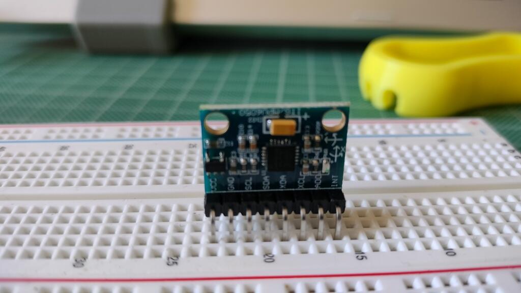
It's a motion sensor that comes packed with a 3-axis gyroscope, a 3-axis accelerometer and a Digital Motion Processor™ (DMP™) that enables it to process a complex 9-axis MotionFusion algorithm.
The gyroscope measures the rate of change of the angular position, which is the rotational velocity, while the accelerometer measures the rate of change of the velocity of an object, which is acceleration. By combining the data from both sensors, it's possible to determine the orientation of an object in three-dimensional space.
In a static object, the accelerometer should measure the acceleration due to gravity along the Z-axis, which is vertical. This value is usually around 9.8 m/s^2, assuming the sensor is at rest and located at sea level.
In addition, the accelerometer should measure zero acceleration along the X and Y axes since the object is not moving. However, in reality, there may be small variations due to factors such as sensor noise, temperature changes, and other environmental factors.
By combining the values from the accelerometer, it is possible to get an accurate sensor orientation.
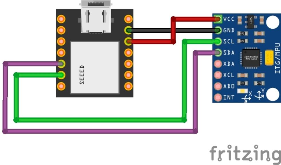
| VCC | Power the sensor (3.3V or 5V) |
| GND | Common GND |
| SCL | SCL pin for I2C communication (GPIO 22) |
| SDA | SDA pin for I2C communication (GPIO 21) |
| XDA | Used to interface other I2C sensors with the MPU-6050 |
| XCL | Used to interface other I2C sensors with the MPU-6050 |
| AD0 | Use this pin to change the I2C address |
| INT | Interrupt pin - can be used to indicate that new measurement data is available |
Battle plan!
1. I will start by wiring up the sensor and the ESP32;
2. After that I will run some code to Serial.print data and make sure It's working;
3. Start the Web server and using Three.js output to a webpage the rotation as well as other data;
4. Create an App that displays the step counter and other info.
5. Send data to another ESP32 That will not only display the data but also record it to an SD Card.
1. Connections:
It's always useful to remember the ESP32 Pinout:

And our simple connection schematic:
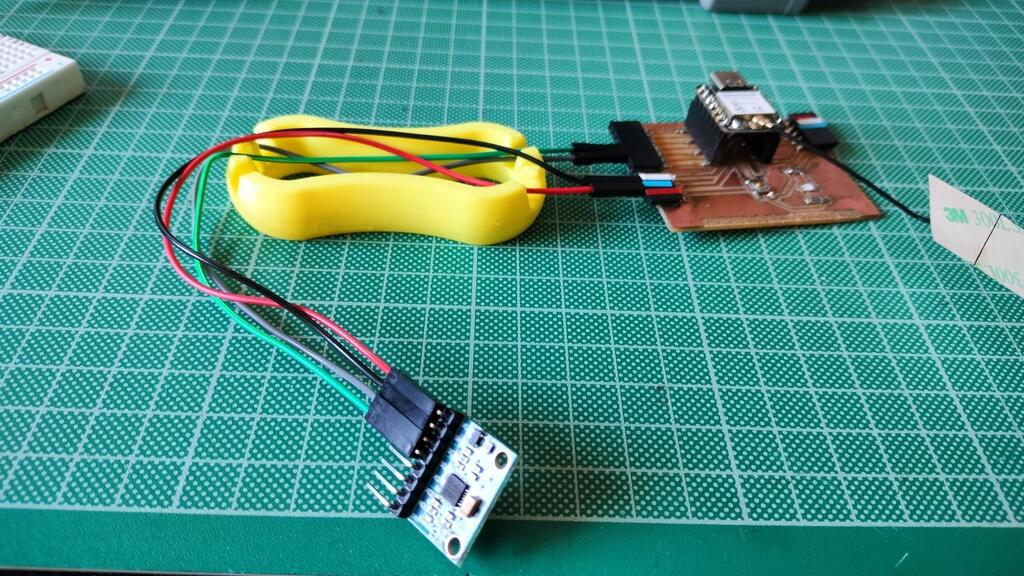
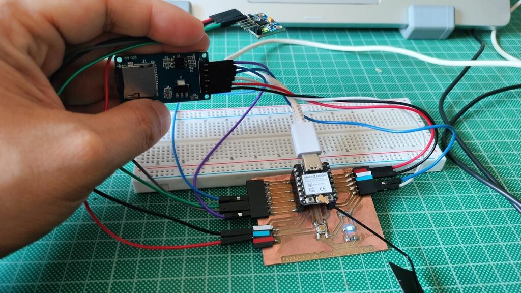
And this is what our real wiring looks like:
Now I get to the initial software part:
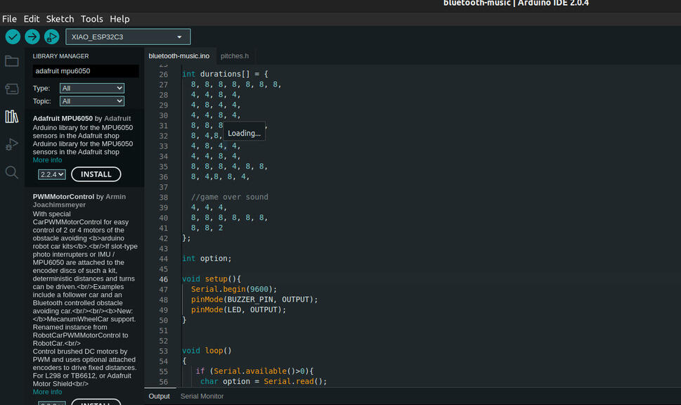
First things, first. Get the libraries:
Open Arduino IDE and add the library "Adafruit mpu6050","Adafruit Unified Sensor","Adafruit Bus IO".
This sketch will allow us to get the data from the readings of the MPU-6050 The source is in the links sections.
// Basic demo for accelerometer readings from Adafruit MPU6050

#include <Adafruit_MPU6050.h>
#include <Adafruit_Sensor.h>
#include <Wire.h>

Adafruit_MPU6050 mpu;

  void setup(void) {
   Serial.begin(115200);
  while (!Serial)
  delay(10); // will pause Zero, Leonardo, etc until serial console opens

  Serial.println("Adafruit MPU6050 test!");

  // Try to initialize!
  if (!mpu.begin()) {
   Serial.println("Failed to find MPU6050 chip");
   while (1) {
    delay(10);
   }
  }
 Serial.println("MPU6050 Found!");

 mpu.setAccelerometerRange(MPU6050_RANGE_8_G);
 Serial.print("Accelerometer range set to: ");
 switch (mpu.getAc celerometerRange()) {
  case MPU6050_RANGE_2_G:
   Serial.println("+-2G");
  break;
  case MPU6050_RANGE_4_G:
   Serial.println("+-4G");
  break;
  case MPU6050_RANGE_8_G:
   Serial.println("+-8G");
  break;
  case MPU6050_RANGE_16_G:
   Serial.println("+-16G");
  break;
 }
  mpu.setGyroRange(MPU6050_RANGE_500_DEG);
  Serial.print("Gyro range set to: ");
  switch (mpu.getGyroRange()) {
  case MPU6050_RANGE_250_DEG:
 Serial.println("+- 250 deg/s");
  break;
  case MPU6050_RANGE_500_DEG:
 Serial.println("+- 500 deg/s");
  break;
  case MPU6050_RANGE_1000_DEG:
 Serial.println("+- 1000 deg/s");
  break;
  case MPU6050_RANGE_2000_DEG:
 Serial.println("+- 2000 deg/s");
  break;
  }

  mpu.setFilterBandwidth(MPU6050_BAND_5_HZ);
  Serial.print("Filter bandwidth set to: ");
  switch (mpu.getFilterBandwidth()) {
   case MPU6050_BAND_260_HZ:
    Serial.println("260 Hz");
   break;
   case MPU6050_BAND_184_HZ:
    Serial.println("184 Hz");
   break;
   case MPU6050_BAND_94_HZ:
    Serial.println("94 Hz");
   break;
   case MPU6050_BAND_44_HZ:
    Serial.println("44 Hz");
   break;
   case MPU6050_BAND_21_HZ:
    Serial.println("21 Hz");
   break;
   case MPU6050_BAND_10_HZ:
    Serial.println("10 Hz");
   break;
    Serial.println("5 Hz");
   break;
 }

 Serial.println("");
  delay(100);
}

  void loop() {
  /* Get new sensor events with the readings */
  sensors_event_t a, g, temp;
  mpu.getEvent(&a, &g, &temp);

  /* Print out the values */
  Serial.print("Acceleration X: ");
  Serial.print(a.acceleration.x);
  Serial.print(", Y: ");
  Serial.print(a.acceleration.y);
  Serial.print(", Z: ");
  Serial.print(a.acceleration.z);
  Serial.println(" m/s^2");

    Serial.print("Rotation X: ");
  Serial.print(g.gyro.x);
  Serial.print(", Y: ");
  Serial.print(g.gyro.y);
  Serial.print(", Z: ");
  Serial.print(g.gyro.z);
  Serial.println(" rad/s");

  Serial.print("Temperature: ");
  Serial.print(temp.temperature);
  Serial.println(" degC");

  Serial.println("");
  delay(500);
}
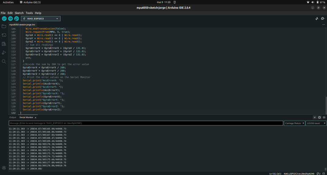
I get these values when the sensor is static:
01:21:37.968 -> Acceleration X: -0.23, Y: -0.11, Z: 9.66 m/s^2
01:21:37.968 -> Rotation X: 0.01, Y: -0.03, Z: 0.00 rad/s
01:21:37.968 -> Temperature: 27.57 degC
A correction will be done in the Sketch code so that the values will be 0 or near 0.
Programming a web server
Creating the web server and displaying data
I have done something similar to this for another week. At the time I used a DHT-11 Sensor.
This time I will add more libraries to the project.
Libraries:
- ESPAsyncWebServer:Provides an easy way to build an asynchronous web server;
- AsyncTCP: The base of ESPAsyncWebServer - A fully asynchronous TCP library, aimed at enabling trouble-free, multi-connection network environments for Espressif's ESP32 MCUs.
- Arduino_JSON: Helper library to abstract away I2C & SPI transactions and registers;
Why use ESPAsyncWebServer instead of the Web server we created the last time?
- Handle more than one connection at the same time;
- When you send the response, you are immediately ready to handle other connections while the server is taking care of sending the response in the background;
- Simple template processing engine to handle templates;
This is the part we will diverge from most of the tutorials around.
I won't... well the Xiao ESP32 won't be serving the html files from SPIFFs but from a Micro SD Card.
Why? Because I want to be able to change the html files without having to recompile the code and upload it to the board.
Before getting the values from the MPU-6050 sensor, I want to try out the MicroSD card.
I will be using a HW-125 MicroSD card module and the wiring schematic for the SD card reader is the following.
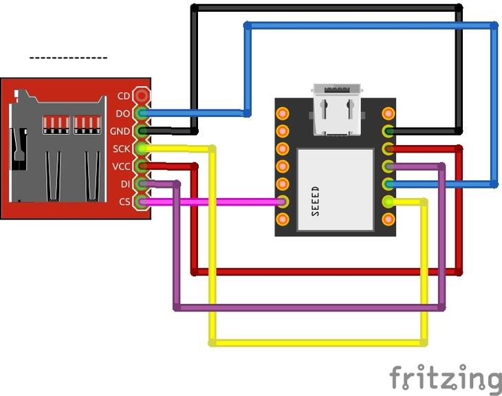
Programming the Web server from the SD CARD
To test the module I will be using the test example from Arduino IDE. It can be found in
File
> Examples > SD > SD test
I need to add the pin number of the CS to the Sketch example for the module to work, It can be done by adding the number of the pin in the "SD.begin" line:
 void setup(){

  Serial.begin(115200);

  if(!SD.begin(7)){

   Serial.println("Card Mount Failed");

  return;

  }

...
After uploading the code to the board, I can see the following in the Serial Monitor:
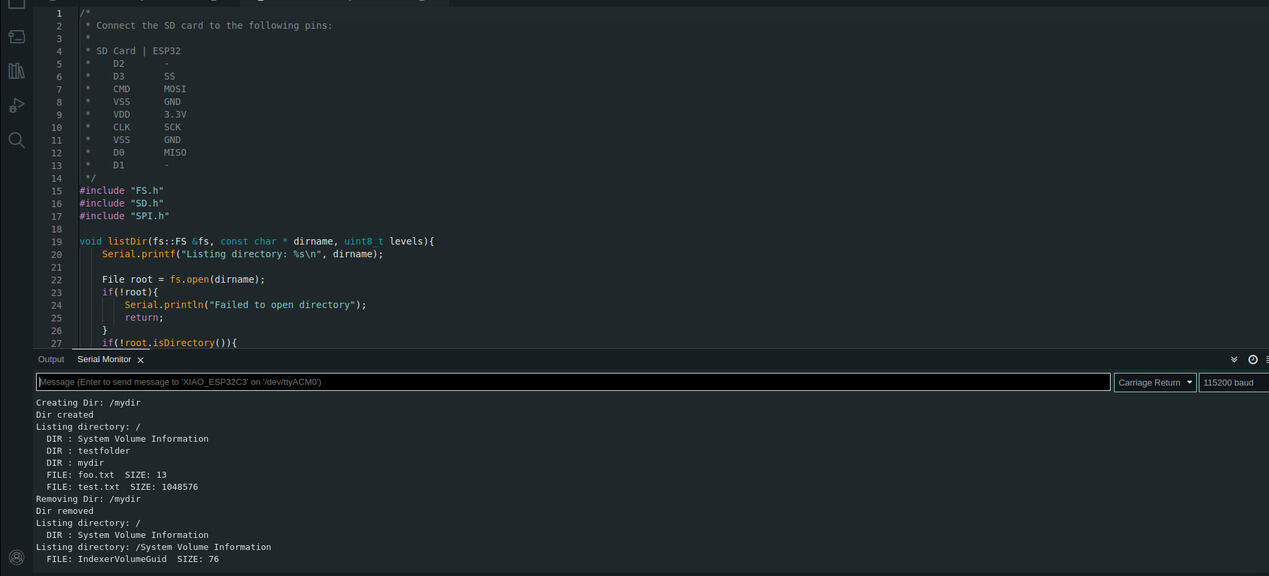
Everything is working.
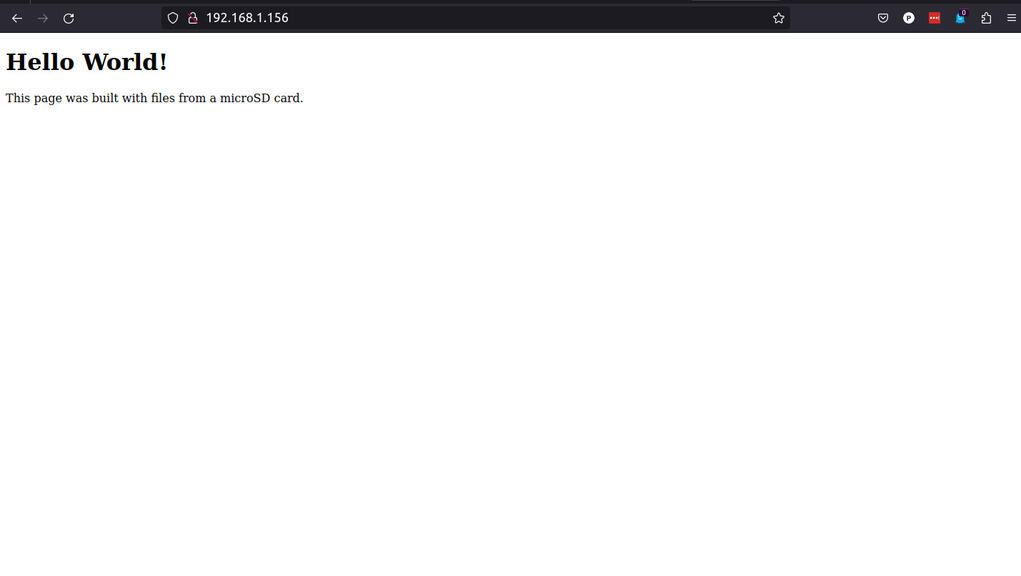
I created an HTML file in the Micro SD card. An hello world of sorts: index.html
<!DOCTYPE HTML>
<html>
<head>
  <title>XIAO ESP32 Web Server
  </title>
</head>
<body>
  <h1>Hello World!</h1>
  <p>This page was built with files from a microSD card.</p>
</body>
</html>
And here is the Sketch for the Async Webserver:
Notice that the pin for CS is defined.
/*
 Based on Rui Santos Sketch that can be found in https://RandomNerdTutorials.com/esp32-web-server-microsd-card/
*/
#include <Arduino.h>
#include <WiFi.h>
#include <AsyncTCP.h>
#include <ESPAsyncWebServer.h>
#include "FS.h"
#include "SD.h"
#include "SPI.h"

// Replace with your network credentials
const char* ssid = "REPLACE_WITH_YOUR_SSID";
const char* password = "REPLACE_WITH_YOUR_PASSWORD";

// Create AsyncWebServer object on port 80
AsyncWebServer server(80);

void initSDCard(){
 if(!SD.begin(7)){
  Serial.println("Card Mount Failed");
  return;
 }
 uint8_t cardType = SD.cardType();

 if(cardType == CARD_NONE){
  Serial.println("No SD card attached");
  return;
 }

 Serial.print("SD Card Type: ");
 if(cardType == CARD_MMC){
  Serial.println("MMC");
 } else if(cardType == CARD_SD){
  Serial.println("SDSC");
 } else if(cardType == CARD_SDHC){
  Serial.println("SDHC");
 } else {
  Serial.println("UNKNOWN");
 }
 uint64_t cardSize = SD.cardSize() / (1024 * 1024);
 Serial.printf("SD Card Size: %lluMB\n", cardSize);
}

void initWiFi() {
 WiFi.mode(WIFI_STA);
 WiFi.begin(ssid, password);
 Serial.print("Connecting to WiFi ..");
 while (WiFi.status() != WL_CONNECTED) {
  Serial.print('.');
  delay(1000);
 }
 Serial.println(WiFi.localIP());
}

void setup() {
  Serial.begin(115200);
  initWiFi();
  initSDCard();

  server.on("/", HTTP_GET, [](AsyncWebServerRequest *request){
  request->send(SD, "/index.html", "text/html");
  });

  server.serveStatic("/", SD, "/");

  server.begin();
}

void loop() {

}
Compiling gave me an error, but after googling it a bit I found a solution here: ESPAsyncWebserver github issues.
line: 832
change from: return IPAddress(0U);
change to: return IPAddress((uint32_t)0);
And it worked!
Next step: Sensor readings to the HTML page.
The first problem I'm going to face is to connect both the MPU6050 and the HW-125. The HW-125 takes a lot of pins and in my board I used a couple of them for the button and the LED.
The solution is to define new pins for the MISO,MOSI, SCK and CS connection. Yes, the ESP32 allows that.
In our sketch we must define this pins and create a new SPI class
First I added this on the top of my sketch:
#define SCK  5

#define MISO  20

#define MOSI  10

#define CS  21


SPIClass spi = SPIClass(SPI);
After that, in the void setup function I need to register the different pins:
    spi.begin(SCK, MISO, MOSI, CS);


    if (!SD.begin(CS,spi,80000000)) {
Tempe
      Serial.println("Card Mount Failed");

      return;

    }
Here is the schematic:
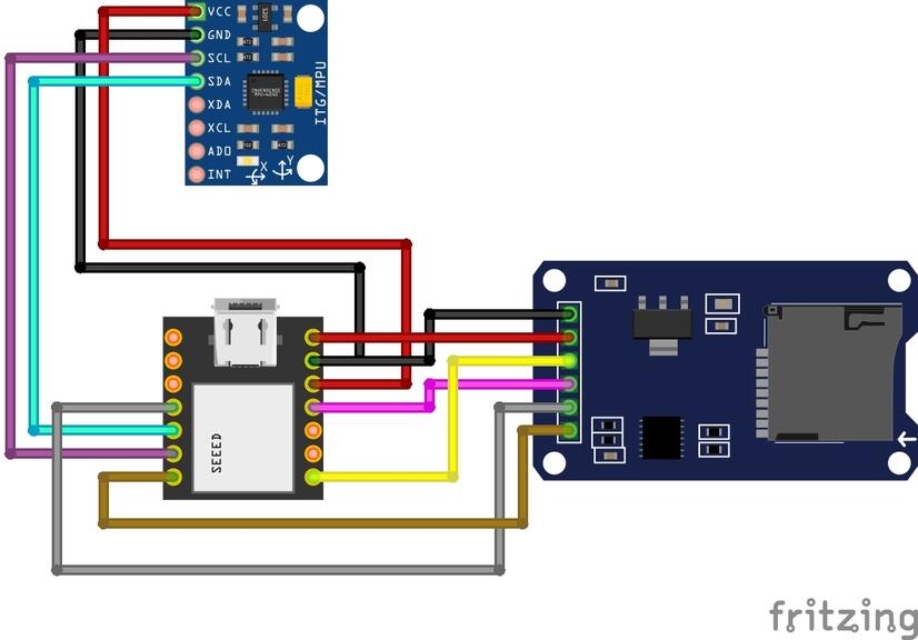
And here is what it looks like:
On with the show. We are almost done:
I'm going to be using the Three.js library that Professor Neil mentioned in class.
I found a cool tutorial that pointed me in the right direction (It's linked in the links section).
I will be using a different HTML, CSS and Javascript from that of the tutorial and I also need to write a new Sketch as the one in the tutorial is a bit outdated.
You can find the HTML file here.
A brief explanation of how it all works:
The Three.js file is included in the header from the cloudflare CDN.
In HTML we have references with ID's, like in the accelerometer part: id="accX", the Javascript file targets this ID's and passes the data from the sensor to this "container".
I also have an ID called 3Dcube.
In the sketch we store the values in JSON format and those values will be where the javascript gets its values from and "updates" the page.
/*
  Pedro Candeias
  Based on a Sketch by Rui Santos from  https://RandomNerdTutorials.com/esp32-web-server-microsd-card/

  Permission is hereby granted, free of charge, to any person obtaining a copy
  of this software and associated documentation files.

  The above copyright notice and this permission notice shall be included in all
  copies or substantial portions of the Software.
*/

#include <Arduino.h>
#include <WiFi.h>
#include <AsyncTCP.h>
#include <ESPAsyncWebServer.h>
#include <Adafruit_MPU6050.h>
#include <Adafruit_Sensor.h>
#include <Arduino_JSON.h>
#include "FS.h"
#include "SD.h"
#include "SPI.h"


#define SCK 5
#define MISO 20
#define MOSI 10
#define CS 21
SPIClass spi = SPIClass(SPI);

// Replace with your network credentials
const char* ssid = "REPLACE_WITH_YOUR_SSID";
const char* password = "REPLACE_WITH_YOUR_PASSWORD";

// Create AsyncWebServer object on port 80
AsyncWebServer server(80);


// init SD card
void initSDCard() {
 if (!SD.begin(CS, spi, 80000000)) {
  Serial.println("Card Mount Failed");
  return;
 }
 uint8_t cardType = SD.cardType();

 if (cardType == CARD_NONE) {
  Serial.println("No SD card attached");
  return;
 }
 uint64_t cardSize = SD.cardSize() / (1024 * 1024);
 Serial.printf("SD Card Size: %lluMB\n", cardSize);
}

// Create an Event Source on /events
AsyncEventSource events("/events");

// Json Variable to Hold Sensor Readings
JSONVar readings;

// Timer variables:

// Create a sensor object
Adafruit_MPU6050 mpu;

sensors_event_t a, g, temp;

float gyroX, gyroY, gyroZ;
float accX, accY, accZ;


//Gyroscope sensor deviation
float gyroXerror = 0.07;
float gyroYerror = 0.03;
float gyroZerror = 0.01;

// Init MPU6050
void initMPU(){
 if (!mpu.begin()) {
  Serial.println("Failed to find MPU6050 chip");
  while (1) {
    delay(10);
   }
  }
  Serial.println("MPU6050 Found!");
}

void initWiFi() {
 WiFi.mode(WIFI_STA);
 WiFi.begin(ssid, password);
 Serial.print("Connecting to WiFi ..");
 while (WiFi.status() != WL_CONNECTED) {
  Serial.print('.');
  delay(1000);
 }
 Serial.println(WiFi.localIP());
}JSONbr>
 if(abs(gyroX_temp) > gyroXerror)  {
  gyroX += gyroX_temp/50.00;
 }

 float gyroY_temp = g.gyro.y;
 if(abs(gyroY_temp) > gyroYerror) {
  gyroY += gyroY_temp/70.00;
 }

 float gyroZ_temp = g.gyro.z;
 if(abs(gyroZ_temp) > gyroZerror) {
  gyroZ += gyroZ_temp/90.00;
 }

 readings["gyroX"] = String(gyroX);
 readings["gyroY"] = String(gyroY);
 readings["gyroZ"] = String(gyroZ);

 String jsonString = JSON.st                ringify(readings);
 return jsonString;
}

String getAccReadings() {
 mpu.getEvent(&a, &g, &temp);
 // Get current acceleration values
 accX = a.acceleration.x;
 accY = a.acceleration.y;
 accZ = a.acceleration.z;
 readings["accX"] = String(accX);
 readings["accY"] = String(accY);
 readings["accZ"] = String(accZ);
 String accString = JSON.stringify (readings);
 return accString;
}

void setup() {
 Serial.begin(115200);
 spi.begin(SCK, MISO, MOSI, CS);

 initWiFi();
 initMPU();
 initSDCard();

 server.on("/", HTTP_GET, [](AsyncWebServerRequest* request) {
    r  equest->send(SD, "/index.html", "text/html");
 });

 server.serveStatic("/", SD, "/");


 server.on("/reset", HTTP_GET, [](AsyncWebServerRequest *request){
  gyroX=0;
  gyroY=0;
  gyroZ=0;
  request->send(200, "text/plain", "OK");
 });

 server.on("/resetX", HTTP_GET, [](AsyncWebServerRequest *request){
  gyroX=0;
  request->send(200, "text/plain", "OK");
 });

 server.on("/resetY", HTTP_GET, [](AsyncWebServerRequest *request){
  gyroY=0;
  request->send(200, "text/plain", "OK");
 });

 server.on("/resetZ", HTTP_GET, [](AsyncWebServerRequest *request){
  gyroZ=0;
  request->send(200, "text/plain", "OK");
 });

 // Handle Web Server Events
 events.onConnect([](AsyncEventSourceClient *client){
 if(client->lastId()){
  Serial.printf("Client reconnected! Last message ID that it got is: %u\n", client->lastId());
 }
 // send event with message "hello!", id current millis
 // and set reconnect delay to 1 second
 client->send("hello!", NULL, millis(), 10000);
 });
 server.addHandler(&events);

 server.begin();
}


void loop() {
 if ((millis() - lastTime) > gyroDelay) {
  // Send Events to the Web Server with the Sensor Readings
  events.send(getGyroReadings().c_str(),"gyro_readings",millis());
  lastTime = millis();
 }
 if ((millis() - lastTimeAcc) > accelerometerDelay) {
  // Send Events to the Web Server with the Sensor Readings
  events.send(getAccReadings().c_str(),"accelerometer_readings",millis());
  lastTimeAcc = millis();
  }
}
Here is the Javascript file.
The shape was generated using the Torus Knot Geometry from the ThreeJS library site: TorusKnot Geometry
The ThreeJS site allows the manipulation of variables in the generated shapes.
The Torus Knot Geometry shape I'm using in the following example was generated using the variables tested on the ThreeJS library site.
/*
Based on Rui Santos code for the ESP32 MPU-6050 Web Server
Complete project details at https://RandomNerdTutorials.com/esp32-mpu-6050-web-server/
*/

let scene, camera, rendered, cube;

function parentWidth(elem) {
    return elem.parentElement.clientWidth;
}

function parentHeight(elem) {
    return elem.parentElement.clientHeight;
}

function init3D(){
    scene = new THREE.Scene();
    scene.background = new THREE.Color(0x000000);

    camera = new THREE.PerspectiveCamera(75, parentWidth(document.getElementById("3Dcube")) / parentHeight(document.getElementById("3Dcube")), 0.1, 1000);

    renderer = new THREE.WebGLRenderer({ antialias: true });
    renderer.setSize(parentWidth(document.getElementById("3Dcube")), parentHeight(document.getElementById("3Dcube")));

    document.getElementById('3Dcube').appendChild(renderer.domElement);

    // Create a geometry
    const geometry = new THREE.TorusKnotGeometry( 11.362, 0.6336, 125, 12,4,3 );
    // Materials of each face
    var cubeMaterials = [
    new THREE.MeshBasicMaterial({color:0xee7752,wireframe: true }),
    new THREE.MeshBasicMaterial({color:0x73c7e,wireframe: true }),
    new THREE.MeshBasicMaterial({color:0x23a6d5,wireframe: true }),
    new THREE.MeshBasicMaterial({color:0x23d5ab,wireframe: true }),
    new THREE.MeshBasicMaterial({color:0xee7752,wireframe: true }),
    new THREE.MeshBasicMaterial({color:0x0077b6,wireframe: true }),
    ];

    const material = new THREE.MeshFaceMaterial(cubeMaterials);

    cube = new THREE.Mesh(geometry, material);
    scene.add(cube);
    camera.position.z = 30;
    renderer.render(scene, camera);
}

// Resize the 3D object when the browser window changes size
function onWindowResize(){
    camera.aspect = parentWidth(document.getElementById("3Dcube")) / parentHeight(document.getElementById("3Dcube"));
    //camera.aspect = window.innerWidth /  window.innerHeight;
    camera.updateProjectionMatrix();
    //renderer.setSize(window.innerWidth, window.innerHeight);
    renderer.setSize(parentWidth(document.getElementById("3Dcube")), parentHeight(document.getElementById("3Dcube")));

}

window.addEventListener('resize', onWindowResize, false);

// Create the 3D representation
init3D();

// Create events for the sensor readings
if (!!window.EventSource) {
    var source = new EventSource('/events');

    source.addEventListener('open', function(e) {
    console.log("Events Connected");
    }, false);

    source.addEventListener('error', function(e) {
    if (e.target.readyState != EventSource.OPEN) {
        console.log("Events Disconnected");
    }
    }, false);

    source.addEventListener('gyro_readings', function(e) {
    //console.log("gyro_readings", e.data);
    var obj = JSON.parse(e.data);
    document.getElementById("gyroX").innerHTML = obj.gyroX;
    document.getElementById("gyroY").innerHTML = obj.gyroY;
    document.getElementById("gyroZ").innerHTML = obj.gyroZ;

    // Change cube rotation after receiving the readings
    cube.rotation.x = obj.gyroY;
    cube.rotation.z = obj.gyroX;
    cube.rotation.y = obj.gyroZ;
    renderer.render(scene, camera);
    }, false);

    source.addEventListener('accelerometer_readings', function(e) {
    console.log("accelerometer_readings", e.data);
    var obj = JSON.parse(e.data);
    document.getElementById("accX").innerHTML = obj.accX;
    document.getElementById("accY").innerHTML = obj.accY;
    document.getElementById("accZ").innerHTML = obj.accZ;
    }, false);
}

function resetPosition(element){
    var xhr = new XMLHttpRequest();
    xhr.open("GET", "/"+element.id, true);
    console.log(element.id);
    xhr.send();
}
Creating the sketch in Processing and interfacing with the MPU6050 sensor.
I haven't played with Processing or P5.js in a long time. Long as in more than a decade.
I assume Processing radically change in that time.
So I made a little sketch to show the data from the gyroscope and send it over serial to Processing for visualization.
It's a very simple sketch, but it's a start.
            #include <Wire.h>
            #include <Adafruit_Sensor.h>
            #include <Adafruit_MPU6050.h>

             Adafruit_MPU6050 mpu;

            void setup() {
             Serial.begin(9600);
             while (!Serial) {
               delay(10);
             }

             Wire.begin();
             mpu.begin();
             mpu.setAccelerometerRange(MPU6050_RANGE_8_G);
             mpu.setGyroRange(MPU6050_RANGE_500_DEG);
            }

            void loop() {
             sensors_event_t a, g, temp;
             mpu.getEvent(&a, &g, &temp);

             float ax = a.acceleration.x;
             float ay = a.acceleration.y;
             float az = a.acceleration.z;
             float gx = g.gyro.x;
             float gy = g.gyro.y;
             float gz = g.gyro.z;

             Serial.print(ax); Serial.print(",");
             Serial.print(ay); Serial.print(",");
             Serial.print(az); Serial.print(",");
             Serial.print(gx); Serial.print(",");
             Serial.print(gy); Serial.print(",");
             Serial.println(gz);
            }
Now I need to install processing in my Linux Distro:
- Go to https://processing.org/download and download "Processing x.x for Linux" (x.x = 4.2 at the time of I'm writing this)
- Extract the archive;
- In a terminal prompt, move into the folder and type "install.sh" and press enter.
- That is it!
Here is the processing code:
import processing.serial.*;

Serial port;

float ax, ay, az, gx, gy, gz;

void setup() {
 size(400, 400);
 port = new Serial(this, "COM3", 9600);
}

void draw() {
 background(255);

 if (port.available() > 0) {
  String data = port.readStringUntil('\n');
  if (data != null) {
   String[] values = data.split(",");
   ax = float(values[0]);
   ay = float(values[1]);
   az = float(values[2]);
   gx = float(values[3]);
   gy = float(values[4]);
   gz = float(values[5]);
  }
 }

 translate(width/2, height/2);
 rotateX(-ay * PI/180.0);
 rotateY(-ax * PI/180.0);
 rotateZ(-gz * PI/180.0);
 box(100);
}
It works... just not very well. So I search a bit and found the documentation of a former Fab Academy Student, Jorge Roig, and he got his code from the following site: https://howtomechatronics.com
He has some code in his documentation that I will modify and explain and see if his code works better:
The arduino Sketch:
/*
Arduino and MPU6050 Accelerometer and Gyroscope Sensor Tutorial
by Dejan, https://howtomechatronics.com
*/
#include <Wire.h>
const int MPU = 0x68; // MPU6050 I2C address
float AccX, AccY, AccZ;
float GyroX, GyroY, GyroZ;
float accAngleX, accAngleY, gyroAngleX, gyroAngleY, gyroAngleZ;
float roll, pitch, yaw;
float AccErrorX, AccErrorY, GyroErrorX, GyroErrorY, GyroErrorZ;
float elapsedTime, currentTime, previousTime;
int c = 0;
void setup() {
 Serial.begin(19200);
 Wire.begin();                      // Initialize comunication
 Wire.beginTransmission(MPU);       // Start communication with MPU6050 // MPU=0x68
 Wire.write(0x6B);                  // Talk to the register 6B
 Wire.write(0x00);                  // Make reset - place a 0 into the 6B register
 Wire.endTransmission(true);        //end the transmission
 /*
 // Configure Accelerometer Sensitivity - Full Scale Range (default +/- 2g)
 Wire.beginTransmission(MPU);
 Wire.write(0x1C);                  //Talk to the ACCEL_CONFIG register (1C hex)
 Wire.write(0x10);                  //Set the register bits as 00010000 (+/- 8g full scale range)
 Wire.endTransmission(true);
 // Configure Gyro Sensitivity - Full Scale Range (default +/- 250deg/s)
 Wire.beginTransmission(MPU);
 Wire.write(0x1B);                   // Talk to the GYRO_CONFIG register (1B hex)
 Wire.write(0x10);                   // Set the register bits as 00010000 (1000deg/s full scale)
 Wire.endTransmission(true);
 delay(20);
 */
 // Call this function if you need to get the IMU error values for your module
 calculate_IMU_error();
 delay(20);
}
void loop() {
     // === Read acceleromter data === //
     Wire.beginTransmission(MPU);
     Wire.write(0x3B); // Start with register 0x3B (ACCEL_XOUT_H)
     Wire.endTransmission(false);
     Wire.requestFrom(MPU, 6, true); // Read 6 registers total, each axis value is stored in 2 registers
     //For a range of +-2g, we need to divide the raw values by 16384, according to the datasheet
     AccX = (Wire.read() << 8 | Wire.read()) / 16384.0; // X-axis value
     AccY = (Wire.read() << 8 | Wire.read()) / 16384.0; // Y-axis value
     AccZ = (Wire.read() << 8 | Wire.read()) / 16384.0; // Z-axis value
     // Calculating Roll and Pitch from the accelerometer data
     accAngleX = (atan(AccY / sqrt(pow(AccX, 2) + pow(AccZ, 2))) * 180 / PI) - 0.58; // AccErrorX ~(0.58) See the calculate_IMU_error()custom function for more details
     accAngleY = (atan(-1 * AccX / sqrt(pow(AccY, 2) + pow(AccZ, 2))) * 180 / PI) + 1.58; // AccErrorY ~(-1.58)
     // === Read gyroscope data === //
     previousTime = currentTime;        // Previous time is stored before the actual time read
     currentTime = millis();            // Current time actual time read
     elapsedTime = (currentTime - previousTime) / 1000; // Divide by 1000 to get seconds
     Wire.beginTransmission(MPU);
     Wire.write(0x43); // Gyro data first register address 0x43
     Wire.endTransmission(false);
     Wire.requestFrom(MPU, 6, true); // Read 4 registers total, each axis value is stored in 2 registers
     GyroX = (Wire.read() << 8 | Wire.read()) / 131.0; // For a 250deg/s range we have to divide first the raw value by 131.0, according to the datasheet
     GyroY = (Wire.read() << 8 | Wire.read()) / 131.0;
     GyroZ = (Wire.read() << 8 | Wire.read()) / 131.0;
     // Correct the outputs with the calculated error values
     GyroX = GyroX + 0.56; // GyroErrorX ~(-0.56)
     GyroY = GyroY - 2; // GyroErrorY ~(2)
     GyroZ = GyroZ + 0.79; // GyroErrorZ ~ (-0.8)
     // Currently the raw values are in degrees per seconds, deg/s, so we need to multiply by sendonds (s) to get the angle in degrees
     gyroAngleX = gyroAngleX + GyroX * elapsedTime; // deg/s * s = deg
     gyroAngleY = gyroAngleY + GyroY * elapsedTime;
     yaw =  yaw + GyroZ * elapsedTime;
     // Complementary filter - combine acceleromter and gyro angle values
     roll = 0.96 * gyroAngleX + 0.04 * accAngleX;
     pitch = 0.96 * gyroAngleY + 0.04 * accAngleY;

     // Print the values on the serial monitor
     Serial.print(roll);
     Serial.print("/");
     Serial.print(pitch);
     Serial.print("/");
     Serial.println(yaw);
}
void calculate_IMU_error() {
     // We can call this funtion in the setup section to calculate the accelerometer and gyro data error. From here we will get the error values used in the above equations printed on the Serial Monitor.
     // Note that we should place the IMU flat in order to get the proper values, so that we then can the correct values
     // Read accelerometer values 200 times
     while (c < 200) {
          Wire.beginTransmission(MPU);
          Wire.write(0x3B);
          Wire.endTransmission(false);
          Wire.requestFrom(MPU, 6, true);
          AccX = (Wire.read() << 8 | Wire.read()) / 16384.0 ;
          AccY = (Wire.read() << 8 | Wire.read()) / 16384.0 ;
          AccZ = (Wire.read() << 8 | Wire.read()) / 16384.0 ;
          // Sum all readings
          AccErrorX = AccErrorX + ((atan((AccY) / sqrt(pow((AccX), 2) + pow((AccZ), 2))) * 180 / PI));
          AccErrorY = AccErrorY + ((atan(-1 * (AccX) / sqrt(pow((AccY), 2) + pow((AccZ), 2))) * 180 / PI));
          c++;
     }
     //Divide the sum by 200 to get the error value
     AccErrorX = AccErrorX / 200;
     AccErrorY = AccErrorY / 200;
     c = 0;
     // Read gyro values 200 times
     while (c < 200) {
          Wire.beginTransmission(MPU);
          Wire.write(0x43);
          Wire.endTransmission(false);
          Wire.requestFrom(MPU, 6, true);
          GyroX = Wire.read() << 8 | Wire.read();
          GyroY = Wire.read() << 8 | Wire.read();
          GyroZ = Wire.read() << 8 | Wire.read();
          // Sum all readings
          GyroErrorX = GyroErrorX + (GyroX / 131.0);
          GyroErrorY = GyroErrorY + (GyroY / 131.0);
          GyroErrorZ = GyroErrorZ + (GyroZ / 131.0);
          c++;
     }
     //Divide the sum by 200 to get the error value
     GyroErrorX = GyroErrorX / 200;
     GyroErrorY = GyroErrorY / 200;
     GyroErrorZ = GyroErrorZ / 200;
     // Print the error values on the Serial Monitor
     Serial.print("AccErrorX: ");
     Serial.println(AccErrorX);
     Serial.print("AccErrorY: ");
     Serial.println(AccErrorY);
     Serial.print("GyroErrorX: ");
     Serial.println(GyroErrorX);
     Serial.print("GyroErrorY: ");
     Serial.println(GyroErrorY);
     Serial.print("GyroErrorZ: ");
     Serial.println(GyroErrorZ);
}
This code is for interfacing an MPU6050 accelerometer and gyroscope sensor with an Arduino board. The sensor measures acceleration and angular velocity along three axes, which are used to calculate the orientation of the sensor in space.
The code starts by including the Wire library for I2C communication. Then, several global variables are declared, including the sensor address (0x68), variables for storing the accelerometer and gyroscope data, and variables for calculating the orientation angles (roll, pitch, and yaw).
The setup() function initializes the serial communication for printing output to the serial monitor, starts the Wire communication with the sensor, and resets the sensor by writing a 0 to the MPU6050 register 6B. Additionally, the function calls calculate_IMU_error() to calibrate the sensor.
The loop() function reads the accelerometer and gyroscope data from the sensor, calculates the orientation angles using a complementary filter that combines the accelerometer and gyroscope values, and prints the results to the serial monitor.
The accelerometer data is read by sending an I2C request to the sensor for six registers starting at address 0x3B. The data is then converted from raw values to acceleration values in g units using a scaling factor of 16384.
The gyroscope data is read by sending an I2C request to the sensor for six registers starting at address 0x43. The data is then converted from raw values to angular velocity values in degrees per second using a scaling factor of 131.
To improve the accuracy of the data, the gyroscope values are corrected for bias by adding previously calculated error values. The complementary filter is used to combine the accelerometer and gyroscope values and obtain a more accurate estimate of the orientation angles.
Finally, the orientation angles are printed to the serial monitor in degrees. The loop function then repeats, updating the orientation angles based on the most recent sensor data.
Now the processing code:
/*
Arduino and MPU6050 IMU - 3D Visualization Example
    by Dejan, https://howtomechatronics.com
*/
import processing.serial.*;
import java.awt.event.KeyEvent;
import java.io.IOException;
Serial myPort;
String data="";
float roll, pitch,yaw;
void setup() {
     size (2560, 1440, P3D);
     myPort = new Serial(this, "COM7", 19200); // starts the serial communication
     myPort.bufferUntil('\n');
}
void draw() {
     translate(width/2, height/2, 0);
      background(233);
   textSize(22);
   text("Roll: " + int(roll) + "     Pitch: " + int(pitch), -100, 265);
   // Rotate the object
   rotateX(radians(-pitch));
   rotateZ(radians(roll));
   rotateY(radians(yaw));

   // 3D 0bject
   textSize(30);
   fill(0, 76, 153);
   box (386, 40, 200); // Draw box
   textSize(25);
   fill(255, 255, 255);
   text("www.HowToMechatronics.com", -183, 10, 101);
   //delay(10);
   //println("ypr:\t" + angleX + "\t" + angleY); // Print the values to check whether we are getting proper values
}
// Read data from the Serial Port
void serialEvent (Serial myPort) {
   // reads the data from the Serial Port up to the character '.' and puts it into the String variable "data".
   data = myPort.readStringUntil('\n');
   // if you got any bytes other than the linefeed:
   if (data != null) {
      data = trim(data);
      // split the string at "/"
      String items[] = split(data, '/');
      if (items.length > 1) {
         //--- Roll,Pitch in degrees
         roll = float(items[0]);
         pitch = float(items[1]);
         yaw = float(items[2]);
     }
   }
}
Did it work better? Kind of...
Application: Creating a Step Counter
Making a step counter:
I will be using Blynk to create a simple app that connects to an ESP32 with a MPU-6050 to display the steps, distance traveled, speed and lastly the current temperature.
Here is the Sketch for the step counter, before sending the data to Blynk.
#include <Adafruit_Sensor.h>
#include <Adafruit_MPU6050.h>
#include <Wire.h>

Adafruit_MPU6050 mpu;
int16_t ax, ay, az;
int16_t gx, gy, gz;

int stepCount = 0;
int lastStepCount = 0;
bool stepDetected = false;

unsigned long lastStepTime = 0;
unsigned long currentTime = 0;
float elapsedTime = 0.0;
float distance = 0.0;
float strideLength = 0.7; // Set your stride length in meters
float speed = 0.0;
float temperature = 0.0;
float weight = 80.0; // Set your weight in kilograms
float calories = 0.0;

const float MET_WALKING = 3.5; // MET value for walking

void setup() {
 Wire.begin();
 Serial.begin(9600);
 while (!Serial) {}

 if (!mpu.begin()) {
  Serial.println("Failed to find MPU6050 chip");
  while (1) {
   delay(10);
   }
 }
 Serial.println("MPU6050 Found!");
 mpu.setAccelerometerRange(MPU6050_RANGE_2_G);
 mpu.setGyroRange(MPU6050_RANGE_250_DEG);

 Serial.println("");
 delay(100);
 Serial.println("Ready!");
}

void loop() {
 sensors_event_t a, g, temp;
 mpu.getEvent(&a, &g, &temp);
 ax=a.acceleration.x;
 ay=a.acceleration.y;
 az=a.acceleration.z;
 gx=g.gyro.x;
 gy=g.gyro.y;
 gz=g.gyro.z;

 float accelerationMagnitude = sqrt(ax * ax + ay * ay + az * az);

 if (accelerationMagnitude > 10 && !stepDetected) {
 stepCount++;
 stepDetected = true;

 // Calculate distance, speed, and calories burned
 currentTime = millis();
 elapsedTime = (currentTime - lastStepTime) / 1000.0;
 distance += strideLength;
 speed = distance / elapsedTime;
 calories += MET_WALKING * weight * elapsedTime / 3600.0; // Calories burned = MET * weight (kg) * time (hours)

 lastStepTime = currentTime;
 } else if (accelerationMagnitude < 8) {
 stepDetected = false;
 }

 if (stepCount != lastStepCount) {
 // Print step count, temperature, distance, speed, and calories burned
 temperature = temp.temperature;
 Serial.print("Step count: ");
 Serial.print(stepCount);
 Serial.print("  Temperature: ");
 Serial.print(temperature);
 Serial.print("  Distance: ");
 Serial.print(distance);
 Serial.print(" meters  Speed: ");
 Serial.print(speed);
 Serial.print(" m/s  Calories: ");
 Serial.print(calories);
 Serial.println(" kcal");

 lastStepCount = stepCount;
 }

 delay(50);
}
The sketch uses the Adafruit MPU6050 library to read the acceleration data from the sensor and calculates the acceleration magnitude.
If the magnitude exceeds a certain threshold (10), it increments a step counter.
To avoid double-counting steps, a flag is set to indicate when a step has been detected.
The step counter is printed to the serial monitor every time it changes.
It also uses the millis() function to calculate the time elapsed since the last step and the strideLength variable to calculate the distance traveled.
The speed is calculated by dividing the distance by the elapsed time.
The temperature is obtained using the getTemperature() method of the MPU6050 library.
The strideLength variable is set to 0.7 meters by default and it's a made up value. If this was a real pedometer the value should match my stride length.
I did some googling to learn how to estimate the calories burned and I am going to use the MET (metabolic equivalent of task) method.
MET values represent the amount of energy expended by a person performing an activity relative to the energy expended while at rest.
For example, a MET of 1 would be the energy expended while sitting quietly, while a MET of 4 would be the energy expended while bicycling at less than 16 km/h, that is for leisure, to work or for pleasure.
Before I go further, I have to create an account in Blynk and set up the initial project.
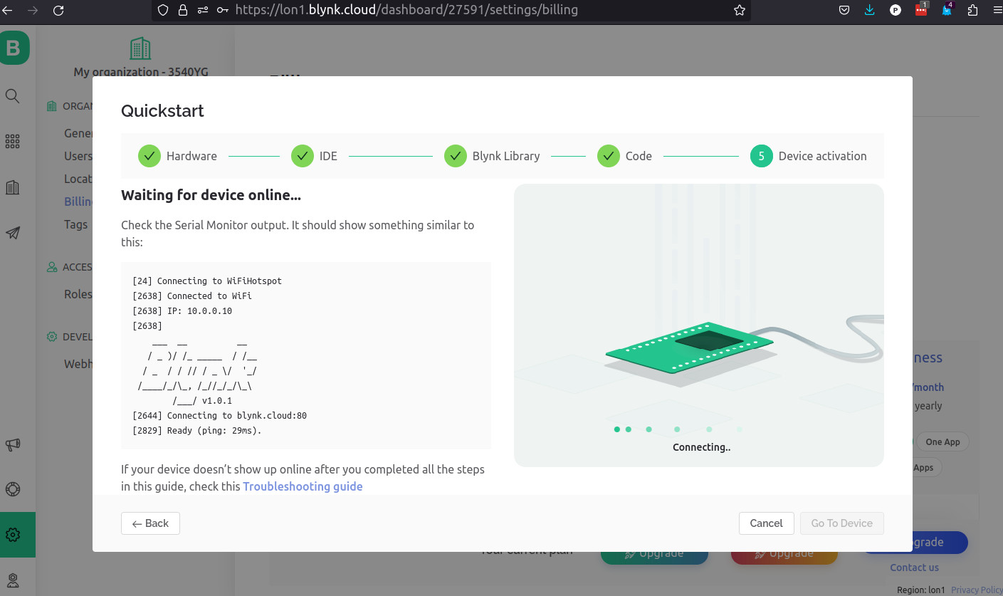
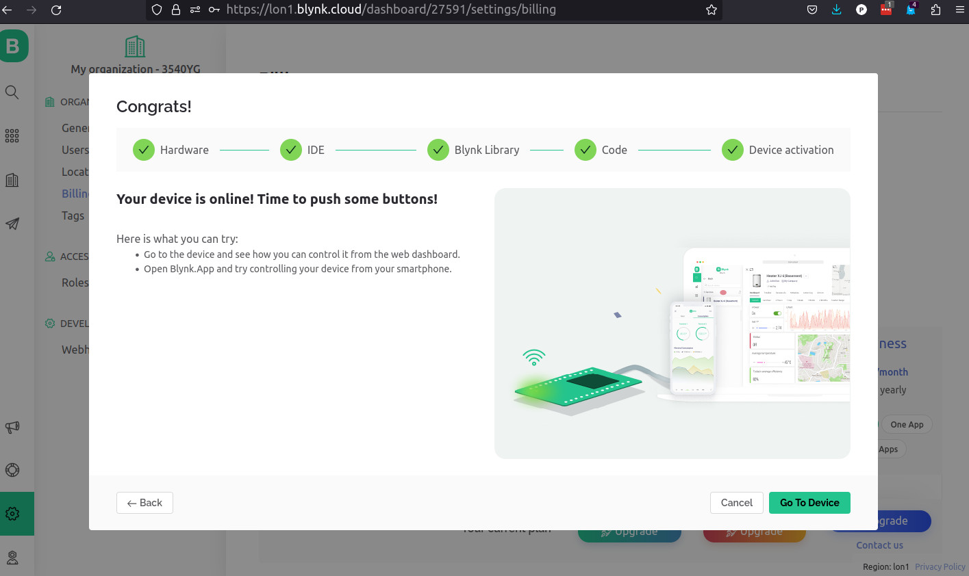
After setting up the account I created the dashboard and the datastreams matching the data I'm sending to Blynk.
Now I have to integrate a way to pass values to Blynk but I'm sure that is pretty easy:
#include <Adafruit_MPU6050.h>
#include <Adafruit_Sensor.h>
#include <Wire.h>
#include <WiFi.h>
#include <WiFiClient.h>
#include <BlynkSimpleEsp32.h>

/* Fill-in information from Blynk Device Info here */
#define BLYNK_TEMPLATE_ID           "xxxx"
#define BLYNK_TEMPLATE_NAME         "Step counter"
#define BLYNK_AUTH_TOKEN            "xxxx"

char ssid[] = "xxxx";
char pass[] = "xxxx";

/* Comment this out to disable prints and save space */
#define BLYNK_PRINT Serial

Adafruit_MPU6050 mpu;
int16_t ax, ay, az;
int16_t gx, gy, gz;

int stepCount = 0;
int lastStepCount = 0;
bool stepDetected = false;

unsigned long lastStepTime = 0;
unsigned long currentTime = 0;
float elapsedTime = 0.0;
float distance = 0.0;
float strideLength = 0.7; // Set your stride length in meters
float speed = 0.0;
float temperature = 0.0;
float calories = 0.0;

void setup() {
     Wire.begin();
     Serial.begin(9600);
     while (!Serial) {}

     Blynk.begin(BLYNK_AUTH_TOKEN, ssid, pass);

     if (!mpu.begin()) {
     Serial.println("Failed to find MPU6050 chip");
      while (1) {
           delay(10);
          }
     }
     Serial.println("MPU6050 Found!");
     mpu.setAccelerometerRange(MPU6050_RANGE_2_G);
     mpu.setGyroRange(MPU6050_RANGE_250_DEG);

     Serial.println("");
     delay(100);
     Serial.println("Ready!");
}

void loop() {
     Blynk.run(); // Update Blynk app
     sensors_event_t a, g, temp;
     mpu.getEvent(&a, &g, &temp);
     ax=a.acceleration.x;
     ay=a.acceleration.y;
     az=a.acceleration.z;
     gx=g.gyro.x;
     gy=g.gyro.y;
     gz=g.gyro.z;

     float accelerationMagnitude = sqrt(ax * ax + ay * ay + az * az);

     if (accelerationMagnitude > 10 && !stepDetected) {
          stepCount++;
          stepDetected = true;

          // Calculate distance, speed, and calories burned
          currentTime = millis();
          elapsedTime = (currentTime - lastStepTime) / 1000.0;
          distance += strideLength;
          speed = distance / elapsedTime;
          calories = distance * 50.0;

          lastStepTime = currentTime;
     } else if (accelerationMagnitude < 8) {
          stepDetected = false;
     }

     if (stepCount != lastStepCount) {
          // Print step count, temperature, distance, speed, and calories burned
          temperature = temp.temperature;
          Serial.print("Step count: ");
          Serial.print(stepCount);
          Serial.print("  Temperature: ");
          Serial.print(temperature);
      Serial.print("  Distance: ");
      Serial.print(distance);
      Serial.print(" meters  Speed: ");
      Serial.print(speed);
      Serial.print(" m/s  Calories: ");
      Serial.print(calories);
      Serial.println(" cal");

      // Send data to Blynk app
      Blynk.virtualWrite(V0, stepCount);
      Blynk.virtualWrite(V1, calories);
      Blynk.virtualWrite(V2, temperature);
      Blynk.virtualWrite(V3, speed);
      Blynk.virtualWrite(V4, distance);

      lastStepCount = stepCount;
      }

      delay(50);
}
Here is Blynk getting the data and displaying it in the dashboard.
Here is the version on the Blynk App in Android.
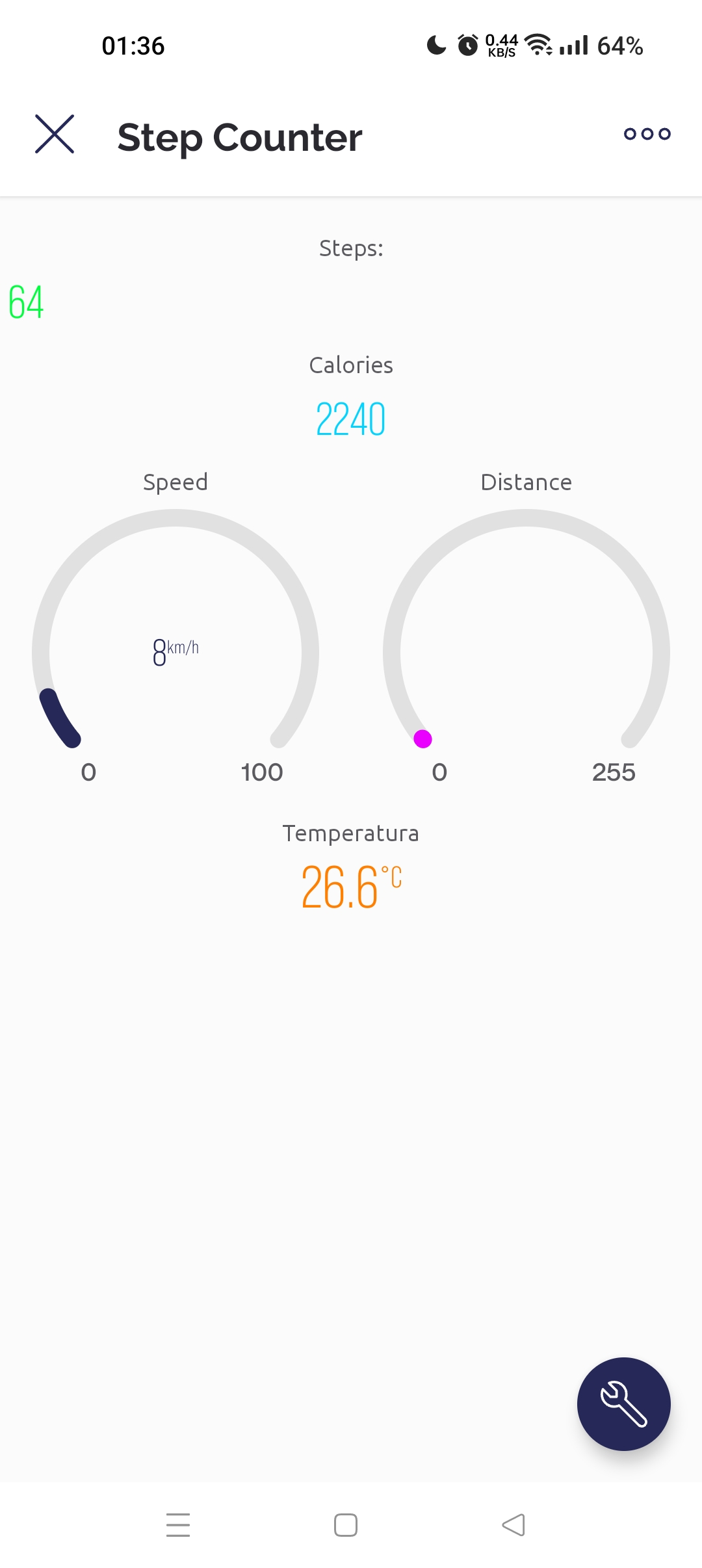
It's pretty obvious that the values are not real as I'm simulating the steps by moving the sensor back-and-forth.
Also, the calculations for the calories are not correct and maybe I'll revise them one day.
For the final project
Files
Learned this week (in no special order)
- Change the crf value for better compression to file size ratio:
ffmpeg -i video.webm -crf 1 -c:v libx264 video.mp4 - When getting the width not divisible by 2 warning on a video compression:
ffmpeg -i blynk.webm -vcodec libx264 \-vf "pad=ceil(iw/2)*2:ceil(ih/2)*2" -r 24 \-y -an video.mp4 - How to build a app with Blynk;
- Using the MPU6050 Sensor;
- Creating a Web server from an SD card;
Notes and Thoughts
This week was just ok, very labor intensive. Just played around with more sensors.
Links
- MPU-6050 6-axis accelerometer/gyroscope
- SD Card reading in Arduino
- Step counter
- Another Step counter
- ESP32 and MPU-6050
- Adafruit BusIO
- Asyn Webserver
- Async TCP
- ESP32 Async Web server tutorial
- Adrián Torres Fab Academy Site
- ESP Asyn Webserver Library
- Async TCP Library
- Jorge Roig Fab Academy page/a>
- How to mechatronics - Arduino MPU6050 accelerometer and Gyroscope.
- MIT APP Inventor BluetoothLE extension
Glossary:
- Accelerometer: Accelerometers are devices that measure acceleration, which is the rate of change of the velocity of an object. They measure in meters per second squared (m/s2) or in G-forces (g).
- Gyroscope: A gyroscope is a device that uses Earth's gravity to help determine orientation. A gyroscope is a wheel mounted in two or three gimbals, which are pivoted supports that allow the rotation of the wheel about a single axis. A set of three gimbals, one mounted on the other with orthogonal pivot axes, may be used to allow a wheel mounted on the innermost gimbal to have an orientation remaining independent of the orientation, in space, of its support.
- IMU: An inertial measurement unit (IMU) is an electronic device that measures and reports a body's specific force, angular rate, and sometimes the orientation of the body, using a combination of accelerometers, gyroscopes, and sometimes magnetometers. IMUs are typically used to maneuver aircraft, including unmanned aerial vehicles (UAVs), among many others, and spacecraft, including satellites and landers.
- Axis: An axis is a fixed reference line for the measurement of coordinates. The plural of axis is 'axes' (pronounced "AXE-ease").
- 3-axis: A 3-axis accelerometer measures acceleration in the x, y and z axes. The x-axis is parallel to the long edge of the board, the y-axis is parallel to the short edge of the board, and the z-axis is perpendicular to the surface of the board.
- 6-axis: A 6-axis accelerometer measures acceleration in the x, y and z axes, and angular velocity around the x, y and z axes. The x-axis is parallel to the long edge of the board, the y-axis is parallel to the short edge of the board, and the z-axis is perpendicular to the surface of the board.
Some of these definitions were generated by AI using ChatGTP.