Before the first actual meeting we, meaning me and Antti Palosaari, his documentation part 1 and part 2, had discussed that we could make a pen plotter. For me the biggest reason for this choice was that it would be fairly easy to understand and make. I also had made a pen plotter called SER-CNC, SER meaning Sähkö- ja Elektroniikka Romu, from electronics waste before so I had some knowledge about the automation.
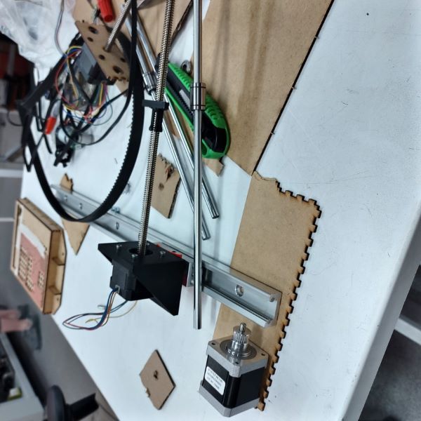
In the first meeting we started to go through the components that we had available. I brought an old rail that I had laying around and Fab Lab had some guide shafts, stepper motors, stepper motors with threaded rods, pulleys and belts. We were discussing if we should use the CoreXY, but ultimately decided not to, to have an machine where the kinematics would be easier to understand and troubleshoot. First we were going to use threaded rods to drive X and Y axes but Fab Lab instructor Gleb Bulygin suggested that we could use belt to drive one of the axis. This proved to be a great suggestion because it gave us some wiggle room to connect separetly designed parts later. We created a quick layout of how to parts would be connected and assembled.
General layout of the components
Rail would be the main structure and it would have plates under it on both ends. On one end would be a stepper motor with pulley and on the other end would be an idler pulley. The belt woudl then connect to the structure on top of the rail carriage. On top of the carriage would be a stepper with threaded rod and a guide shaft. We decided that Antti would design the part on top of the carriage and I would do the plates with the pulley system. Antti would also make a solid pen mount since he would decide the distance between guide shaft and threaded rod. I would also be in charge of the control system since I had prior experience in that. I was a bit suspicios about using only one guide shaft and Antti was a bit of suspicios about plans to laser cut the pulley system. We decided to give each other the freedom to make their choices and redesign them if necessary.
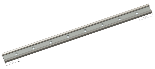
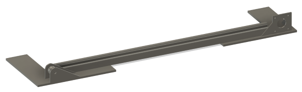
Since the distance to the end of the rail was different on both ends, I decided to make a rough model of the whole rail.
Rail 3D model
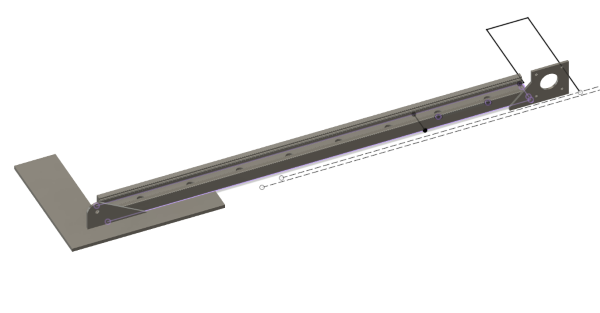
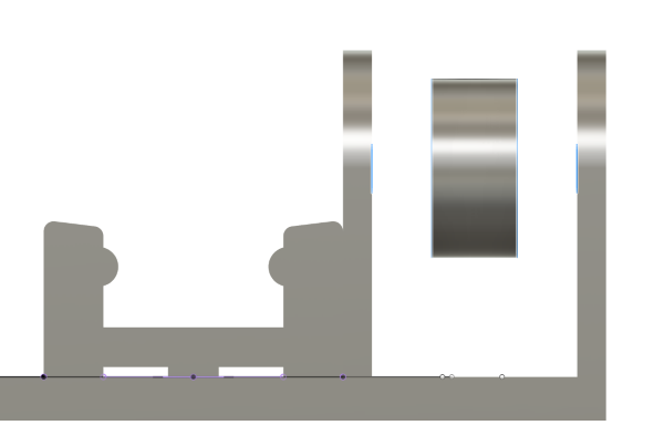
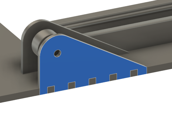
After that I started to model the plates that the rail would mount to. These plates would also work as mounting for the belt drive and as support feet for the machine. In the first meeting we had decided that the belt would start 5 mm from the rail. I wanted to use a bolt to support the top part of the idler mount but with 3 mm MDF plate there wouldn't be enough room for a nut. So we changed the distance to 10 mm.
Starting to model the belt systemEnough space for nuts on both sides
I used different parameters for the base plate thickness and for other plate plate thickness, since I knew that I would like to cut the base plate out of thicker plywood and other parts out of 2.9 mm MDF. I modeled the stepper motor mount according to nema 17 standard.
Necessary parts modeled
When modeling the parts I rushed a bit and there are couple of things that could have been improved. On the idler side I could have made the base plate bit bigger so the pulley support would have a better vertical support. With glue it hold fine.
A bit weak joint
The registering hole for the stepper motor came a bit too tight. This was solved by using a cork spacer that I found in Fab Lab.
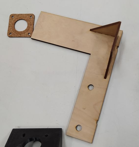
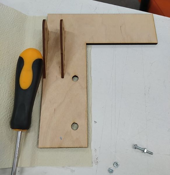
Assemling my laser cut design
I laser cut my designs and glued them together.
Stepper side asssembled. You can also see the cork spacer.Idler side glued. You can also see the bolt that will hold the idler and support the top part.
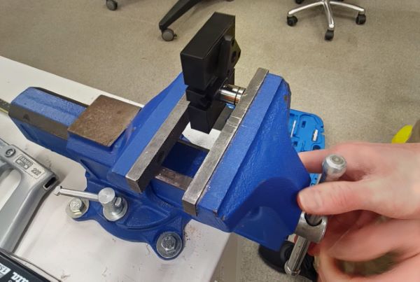
When we both had our parts ready we got together and assembled the parts. We had to drill a couple of holes larger to get the fitment right. The guide shaft fitted really snuggly and provided goot support. Antti had designed the solid pen mount so we could test the XY-axes with a pen. We used a bench vise to press the guide bearing in to the pen mount.
Pressing guide bearing to pen mount
We used a zip tie to wedge the belt to the belt mounts on the carriage.
Assembled machine. Belts still only loosely tied.
I had an arduino uno with a generic ebay/aliexpress CNC shield V3. I downloaded GRBL extracted and installed folder named as grbl as .ZIP library to Arduino IDE. GRBL has a great wiki site that explains the installation and flashing very well. After installing it as a library I could go File → Examples → grbl → grblUpload and then just upload it without changing anything.
Chilipeppr is a website that allows people to create different kind of workspaces to control their hardware. Two different ready made GRBL workspaces were used as CNC controllers. To get the website communicating with the GRBL through serial port a Serial Port JSON Server need to be running. When running the server first time you need to grant it web access in windows firewall.
The shield was meant for stepstick a4988 stepper motor drivers but Fab Lab had DRV8825 drivers but from a quick look they looked to be pin compatible, other than the motor windings. After couple of tries we got the motor windings correct and managed to move the first axis. I was wondering why the axis coordinate didn't update when the stepper turned. This was because I was in GRBL-workspace but I needed to be in jpadie-workspace because we used GRBL 1.1.
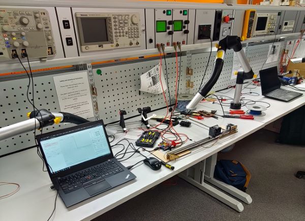
We used lab supply to power the setup
After that we connected the second axis and tuned the steps/mm to be correct for each axis. We also enabled 1/32 microstep resolution to get a bit smoother steps. We adjusted the current by watching the current on the lab supply and testing the stalling torque by blocing the motion with hand. We left it to around 200 mA per axis. We were using 12 volts.
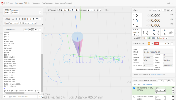
We used the solid pen mount and loaded a pen in there using an O-ring as rubber band and run the default chilipeppr G-code. We used a thick marker and the drag from that was enough to move the paper and the machine itself. This was pretty funny to me because in my knowledge, rigidity and dampening are problems in metal CNC-designs.
Chilipeppr interface and default G-codeIt looks pretty horrible because it doesn't stop drawing on the linking movements. We used a thick marker and drag from that was enough to move the machine and paper.
We discussed how we would implement the Z-axis. We thought that we would either use a servo to lift the pen or we could use a small stepper motor act as a more traditional Z-axis. In our minds both of these solutions had almost of equal problems or unknowns. With the servo we would need a customized version of GRBL that would support servos and maybe some hand modiying of the G-code. The stepper motor solution would be easy on the software side but harder on the hardware side; the modelling of the Z-axis gantry would be harder to design.
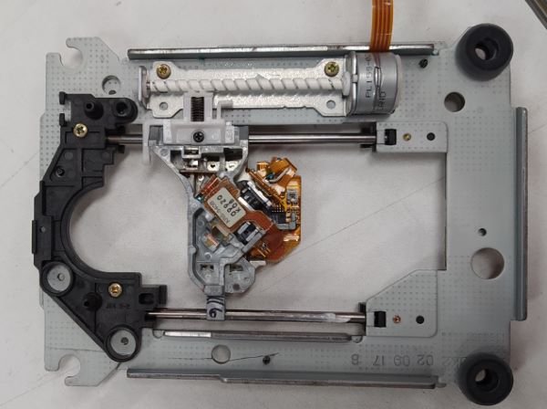
We decided to get pair of old CD-drives from an electronic waste bin. One of them had a small stepper and good guide shafts inside of it.
Stepper and guide shafts inside of old CD-drive
It wouldn't make sense to try to design same pen lifter, so we decided to develop both solutions in paraller. I would design the servo version and Antti the stepper version.
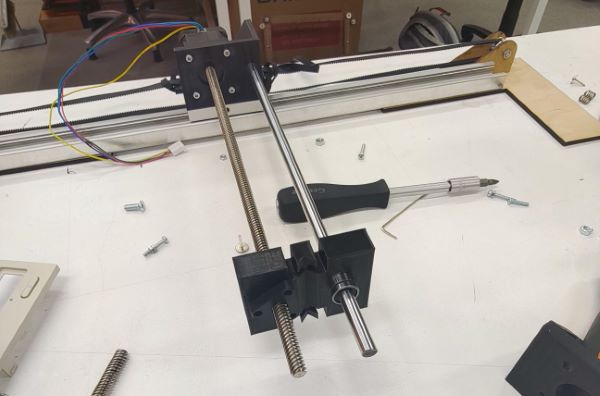
I really like to design laser cuttable parts because it's just so much faster to manuafacture those. I decided to use the guide rails from the CD-drive to limit the movement to one axis. I decided to use the servo just as a simple cam to lift the pen carriage up and down. I thought that I would use just a hot glue or some other easy method to mount the lead screw nut to the pen lifter. I made a pretty tight press fit for the guide bearing. I was thinking that I could made stack a couple of MDF layers on top of each other to reduce the flex in the Y-direction but in the end it wasn't necessary. In the first version I had made a mistake and measured clearance for the servo horn from the center of the lead screw instead of from the outer diameter of it.
Everything hitting the lead screw or lead screw nut
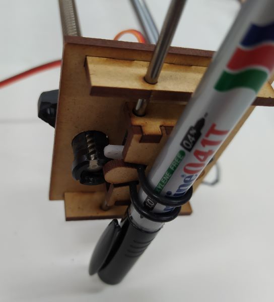
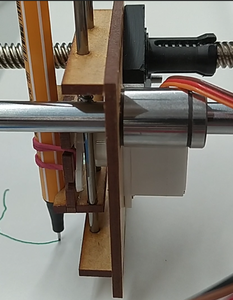
On the second version I moved the servo downwards but know the movement range was limited because the pen carriage hit the bottom of the rails before the servo run out of movement. I tried to make laser cut register for the lead screw nut on the backside of the lifter. In reality it didn't really work and I just used a bolt and nut in the slots meant for the registering part. I also added a spring from normal pen to create a bit more pressure to the pen tip. It work fine with and without it
Interactive 3D model of the last servo designLead screw nut mounted with bolt and guide bearing pressed in
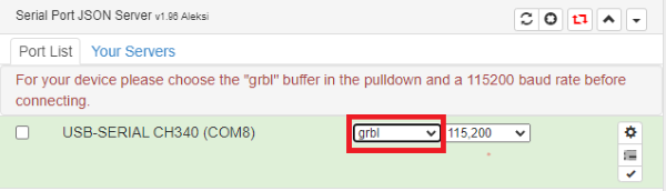
Grbl with Pen Servo Feature was one of the first results that I got from googling GRBL servo, so I decided to use it. I had bit of problems when trying to get it working on the Arduino Uno and I thought it was because I had previous GRBL install messing something up. I decided to try it by making a portable Arduino IDE so I would get a completely fresh install. I had previously used a Arduino Uno copy and now I was using a real genuine one. This caused that the Chilipeppr didn't use GRBL buffer as it's default buffer and caused the system work for a second and then fail. This was solved by just selecting grbl buffer from the dropdown menu.
It's best to always check that you have the correct buffer in Chilipeppr
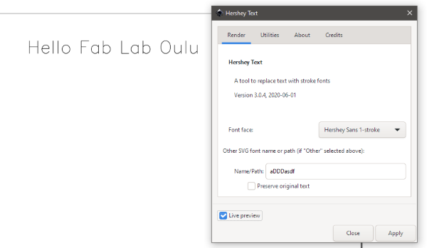
Inkscape has a couple of powerful tools for this type of plotters. First is the hersey text extension in the text extensions submenu. You can just type text in inkscape with normal text tool and convert it to hersey text, meaning it's only one line thick.
Hersey text
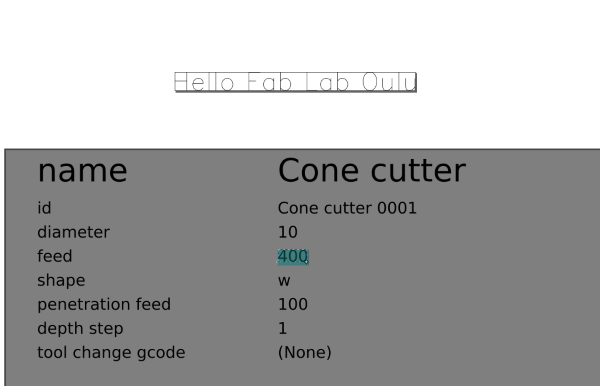
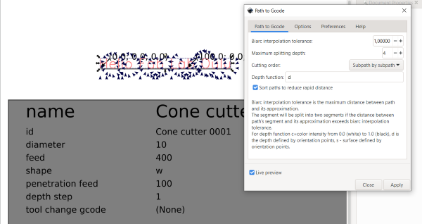
Second extension is Gcodetools. With it you can create G-code from paths. For every step You need to have the path selected and Gcodetools is very specific that you do the steps in correct order. First you select the tool, we used the cone tool. You can manually adjust the feedrate and other setting after applying the tool.
Cone tool. Change feed rate just by typing the new value in to correct place
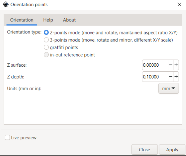
Then you need to set the orientation points.
We used the default settings.
Then you can generate the G-code from path. Change the file location in preferences tab.
Generating the G-code
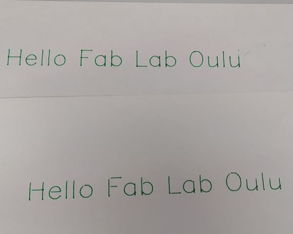
We tuned the GRBL feeds and accelerations a bit but there might be still way more left.
Results the top one was written with the stepper motor pen lifter and the bottom one with the servo versionVidoe with different versions. There is NO sound on the video.
- Servo motor is too slow when lowering the Z-axis. You can see gaps in letters. Might be fixable just by tuning Z-axis feed and acceleration.
- When the Y-axis is far from the stepper motor, it adds a wobbling effect. Maybe caused by bent lead screw. Maybe fixable by using two guide shafts instead of one.