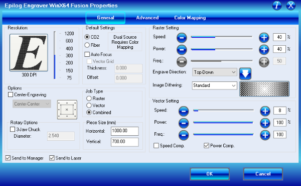
I did the group assignment during the lecture with Toni Kyllönen and our instructor was Behnaz Norouzi. Epilog laser controller uses percentages for Speed and Power. It is weird that the frequency doesn't have any kind of unit in the controller. I thought that I should have tested if the controller would accept a higher number than 100, even when I tested the effect of the frequency the highest number I used was 100.
General things about laser cutter
Basic setting on the laser control
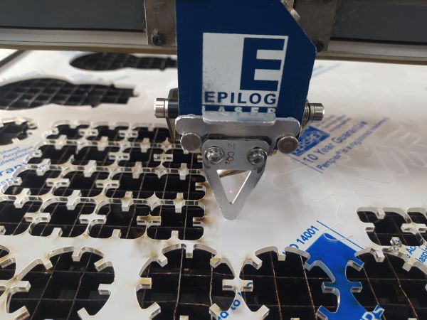
The Laser we used was Epilog Fusion M2 40 Laser. I used the same laser in the invidual tasks. Before using the laser you should always check that the exhaust fan and the air assist are on. Then you can load the material you want to cut or engrave in the laser bed. You should only use materials that you know and that don't produce toxic gases. If you want to use vector mode you need to use thin stroke. Recommended stroke thickness is 0,02 mm, I think the actual value would be one thou because the machine is made in America. One thou would be 0,0254 mm but I haven't confirmed this because the recommended 0,02 mm works just fine. Usually vector mode is used for cutting but you can use it for engraving too. All the engraving in the map that is on my about me page was done using the vector mode. All that isn't in that vector acceptable stroke width will be handled as rasters. Raster mode is mainly used for engraving.
You use the laser from the computer like a printer, you choose to print and then you select the preferences to get to the laser controls that are shown above. In the General tab most important settings are the job type, and settings under the Raster and Vector settings. From advanced tab you can load some pre-sets for different kind of materials. I find that the vector settings for cutting are usually a bit too optimistic and you need to lower the speed or raise the power to get a good cut. In the Color Mapping tab you can specify the laser to use different settings for different colors.
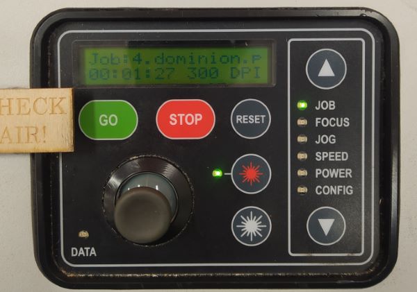
Focus tool on the laser head On the laser you can jog the head close to the area you are going to work on by selecting the jog function and using the joystick to move the head. You can turn on the position laser on by clicking the red star thing on the control panel. By clicking the joystick, you set the new origin of the job. Then you can set the focus by using the focus tool and selecting the focus function. You put the focus tool on the laser head and you want to raise or lower the laser bed in a way that the focus tool is lightly touching the material. You can change the speed that the bed moves by flicking the joystick to the left, the speed is indicated by diamond symbols. Once you are happy with the focus height you confirm it by clicking the joystick. Now you can just check that exhaust and air is on and confirm that you are going to do the right job. Then just press GO and keep a close eye on the process in case there is problems.
Cutting; speed & power
Cuts with different power and speed settings
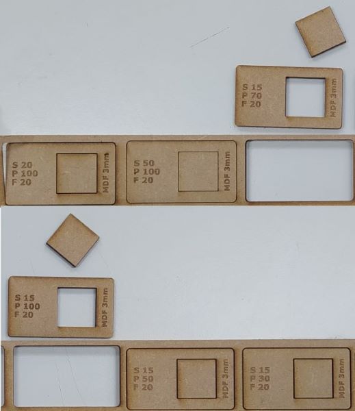
We started testing different cutting parameters by cutting 3 mm MDF. In the first cut we used default values from the library that they have in Fab Lab. We used Speed 20%, Power 100%, and Frequency 20. All the settings used are engraved in the wood with their correct letters. The defaults weren't able to cut through. Before we had noticed that, we had already put a next job in line with higher speed equal to 50%. Of course, that didn't cut through either. We then lowered the speed to 15%, kept the power at 100% and frequency at 20 This was the first cut that went through. We then lowered the power to 70 and kept the rest of the settings same. That cut was also succesful. We then tried cutting with power at 30% and 50% but they failed.
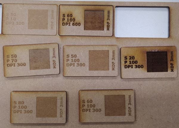
Engraving; speed, power & DPI
Engraving with different power, speed and DPI settings
We then changed to test different parameters in raster mode. I think bottom left was the default settings and they were: Speed 80%, Power 100% and DPI 300. Since engraving area was quite small and people have had problems with fast engraving on small areas, we decided to keep the speed under 60 in the following tests. We also didn't want to use smaller DPI than 300 because last time they did it the belt snapped. I was quite suprised by how much darker the part with the DPI set to 600 came out. The two parts with different DPI are the top and bottom center ones. After Toni Kyllönen and Behnaz Norouzi talked about how the dots are closer and overlap more, It made sense to me. You could also think that you are putting twice the power in the same area as before, so it should be a lot darker.
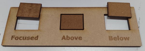
Focus
Cutting and engraving in focus, above the focus and below the focus
Then we tried to set the focus to diferent distances. First we made a control with the correct focus and you can see that the text is clear and the cut went through. Then we lowered the cutting plane so the focus plane would be above the material. You can see that the cut didn't go through and the line where it should have cut were much thicker than usually. You can also see that the text is fuzzy and the transition between the engraved and not engraved parts are not as sharp as in the control. We then moved the focus below the material but we couldn't move it below the focus as much we did move it above because we didn't want the machine itself to hit the material. I think this is the reason why the below part was cut while the above wasn't. I like to think the beam as X-shape where the focus point is in the middle of the X. The beam get wider if you move above or below that point. I think it would have been useful to use the same out of focus distance during the above and below tests, then you would maybe have seen if the beam is actually symmetric. It would also be useful to know if you I should prefer to have the focus little bit over or under the surface of the material. Now I put the focus a bit lower because I think that that way the center of the focus would be in the center of the material. Now we just moved it random amount up and almost as far down as it could go.
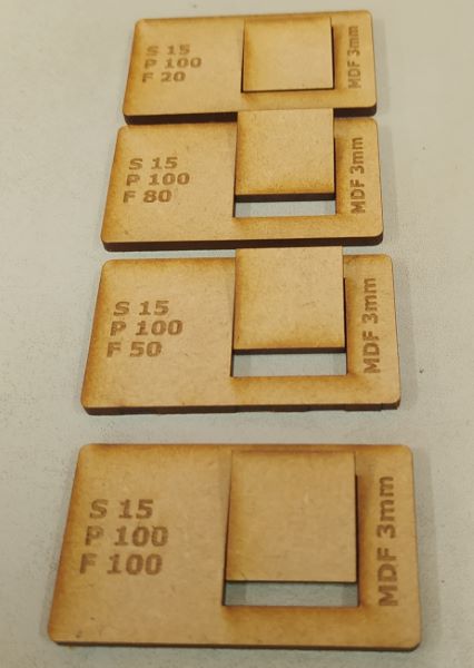
Cutting; frequency
Cutting with different frequencys
We forgot to test the different frequencys in the lectures. So I tested them by myself. I used the same template that we had used in the lectures and 3 mm MDF. I made test cuts with different frequencys ranging from 10 to 100 and I couldn't see any difference. I then tuned the speed up so the cut wouldn't go fully through. I tried to make that cut with 10 and 100 frequencys. I couldn't see a difference between those either. Then I changed to acrylic to see if that would make a differrence, because I thougth that the acrylic might melt differently with different frequencys. It didn't or the differency was so small that I couldn't see it with my bare eyes. I am still wondering if there would be a difference when you are cutting something more flammable, like cardboard.
Kerf
Kerf testing pieces that I made
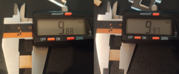
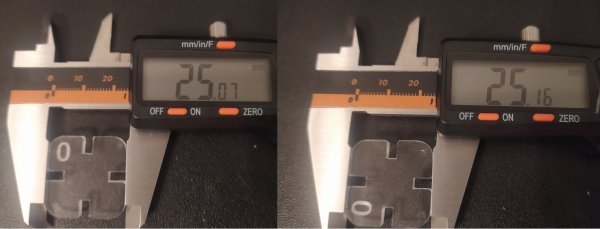
In the lecture we measured kerf but the file that we used to measure it had a mistake in it. The path that the laser travelled wasn't actually 10x10 mm. The error was just big enough that I didn't think it as a measurement error when measuring the cut parts inner and outer dimensions. So I made my own file to measure the kerf. I would recommend to change the size of the square to be maybe double the dimensions so it wouldn't drop under the laser bed so easily. When measuring the kerf I could see that the measurements were different in X- and Y-directions. We talked that the kerf can be different between X- and Y-directions during the group assignment but I think it would be kinda fun experiment to try and find out is the difference just the kerf or does the laser have some unaccarucay in one of the axis. When the laser was cutting in X-direction the kerf in 3 mm MDF was 0,12 mm and when the laser was cutting in the Y-direction the kerf was 0,03 mm. I was using my cheap 15$ calipers for the measurements so they are not accurate but I think the diffrence between the measurements are real. In the lab with Mitutoyo calipers I had similar results but forgot to document those. The results were also repeatable in acrylic. You could also feel that the circle that I cut wasn't a circle but an ellipse. This will also explain why I had such a hard time getting a good fit in both directions and in the off axis too.
Kerf in different axis in 3 mm MDFKerf in different axis in 3 mm PMMA. The zero marks the origin of the laser.
I almost feel that it is waste of time trying to make a good fit in solid materials if the kerf can really be 4 times larger in one axis than the other. The off axis kerf would then be just anyones quess and the design would be really complicated to calculate all the kerfs in the different directions.
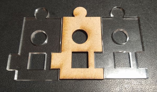
Joint clearance
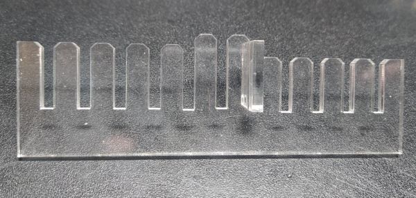
Joint clearance tool that I made. Test piece is in the slot that is thickness - 0,05 mm wide
I made a parametric joint clearance tool in fusion 360. It takes the material thickness and the kerf as parameters. I made it so the center slot with the tallest combs is the material thickness after the cutting and kerf correction. On the side with the shorter combs the slot gets 0,05 mm tighter every slot towards the edge. On the side with the longer combs it gets 0,05 mm wider every slot towards the edge. I thought that 0,05 mm would be a pretty good resolution to feel some difference between the slots. In the end 0,05 mm was too large step since I got a good fit in only two slots. The two slots were the one with the sloth width equal to the material thickness and the one with width equal to thickness - 0,05 mm. If I did this again I would also make the slots to be equal depth because now it is really hard to tell a difference between the thickness and thickness - 0,05 mm slots. I think part of the reason is that the slot with the width equal to thickness is deeper so it has more friction because of that. The thickness + 0,05 mm is a bit too loose to be called a press fit, it's more like a slide fit. I learned that the range for a good press fit in acrylic is smaller than I expected, tolerance is somewhere under 0,15 mm. I would also like to remind that this tool measures the joint clearance only in one direction at the time.
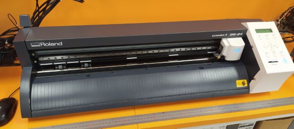
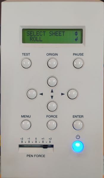
Vinyl cutter. The lever is in the top left and the control panel on the right.
The vinyl cutter in Fab Lab Oulu is Roland CAMM-1 GS-24. When you start the vinyl cutter, you can select the material type, roll, edge or piece. Roll is obviusly the big roll, I think you can use two different widths of rolls. Edge detects only the width of the material while the piece option detects both, width and height. You can load the different materials in to the vinyl cutter by pushing the lever on the right. you need to adjust the rollers depending of the width of your material. The rollers need to be where white marks are on the top. After loading the material and adjusting the rollers you can close the rollers by pulling the lever. you can also adjust the origin in the X-direction while the rollers are open just by moving the cutting gantry and after that holding the origin button to set the new origin. I am not sure if you can adjust the origin in the Y-direction, I should have asked. (EDIT: Apparently you can move the cutting carriage with the arrow buttons on the control panel, this way you can move cutting origin in both directions.) You can bring up the reset settings menu by pressing the menu button twice. On the bottom of the control panel you can adjust the cutting pressure by the slider. You can control the vinyl cutter straigth from Inkscape. You want to select the Roland cutter from the printing menu and got to printing preferences. There you need to select Get from the machine in the Cutting Area settings. Sometimes the machine doesn't actually make the cut and this can be fixed with selecting the Rotate 90deg option. If you need the cut in the certain orientation you can prerotate the design in Inkscape.
In the lecture when we tried different cutting pressures it seemed like lighter pressure might have shredded the design a bit more. From the back of the cuts you could see that the higher pressure cut more in to the backing. The material we used was pretty durable and it didn't seemed to need really precise settings. We also tried to use the cutStudio but weren't succesful. I am pretty sure that it had worked before by just copying and pasting the design from the Inkscape but now we didn't get it the work.
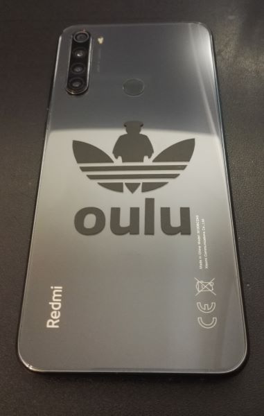
I had made this design that I wanted to cut a couple of stickers. I had made this design years ago in Inkscape so I decided to just scale it to right size which was 50 mm wide. I didn't want to use a full roll, so I dig through the scrap bin and found a suitable matte black vinyl piece from there. I straightened a bit, loaded it in the machine and selected the piece option from the menu. I used Inkscape to print the design. I selected the roland printer and chose the Get from the machine in the Cutting Area settings. I printed the design but nothing happened. I then selected the Rotate 90deg option and printed it again. This time it cut the design. I moved the origin and cut two stickers more. Weeding them was easy because the design was pretty simple and nothing was relly small. Also the material was quite good. Previously I have had problems with weeding because the material I used had such a strong glue that even though I cut with the full pressure, the glue would start instanly bonding again and fused the cut parts together. I then stick some tranfer tape to weeded stickers. I then glued one in my phone, one in my laptop and one is just waiting for a right application.
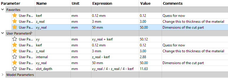
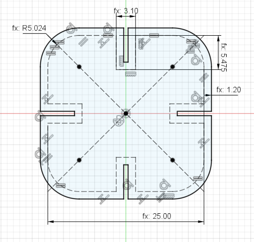
I made the first version of the design in fusion 360 pretty quickly. I started with a center rectangle and added equality constraints to the sides. I added the parameter xy to describe the width and height of the part. I added fillets and used formula xy/5 to calculate the radius. I made a slot in the rectangle and used constraints to stay center of the side. I wanted the width of the slot to be thickness z after the cutting. I made new paramater kerf and gave it a just some near enough value because we hadn't measured the kerf oursleves yet. Now I could calculate the sloth width with z-kerf, I called this parameter internal.
When thinking about slot depth I realized that the xy wouldn't be the real parts dimensions. I made a new paramater called xy_real and used it to calculate xy xy=xy_real+kerf. I also changed the z parameter name to z_real just to keep somewhat regular naming. I wanted that, if you would put three pieces together there woulnd't be gap between the two edge ones. Later I realized that this would prevent the slotting three different pieces in 90° angle but at the moment I carried on. I figured that the slot_depth should be xy_real / 4 - kerf. Later I changed the slot_depth to leave a gap that would be a size of the material thickness. So my sloth_depth was ( xy_real / 4 ) - ( z_real / 4 ) - kerf. I found out that even this was wrong because I already had the kerf included because the sloth depth was measured from the edge of the part and that already had half of the kerf included. Half the kerf is all I need because the other slotting part has the second half. I realized this when I was playing around and trying to use just the offset tool to add the kerf. So I made a new design that had the original sketch with dimensions that didn't include kerf. Then
I added some clearance to the slot depth. I scaled that to material thickness because I thought that if the material is thicker, it would be harder to cut to precise dimensions. So now the sloth_depth was xy_real / 4 - z_real / 4 - 0.05 * z_real.
Now I could use circular pattern to copy the slot to four sides and just trim the extra lines. Then I just extruded the part using z_real as a parameter. I added the values that you are expected to change to favorites so I wouldn't accidentally change the formulas. You can see the heavily constrained sketch, part, and parameters below.
After this I decided to use the offset tool to model the kerf. In the picture at right you can see that I made the original shape I want after laser cutting as construction lines. Here I made the the outline and made it 20 times bigger than it should so you could see the construction lines and the offset line at the same time. In the real design the offset is kerf / 2. Fusion 360 doesen't have a chamfer tool in the sketches so I extruded the part to thickness z_real. I added the chamfers to slots corners and made a new parameter chamfer whit the formula as xy_real / 40.
I also had made a quick version with 8 slots. I made this one before discovering the easier offset method. I made a quick fix for this part because in the first version if you would put two parts next to each other, they would hit each other before hitting the bottom of the slot. I just scaled the parts xy with the formula xy_real * 1.5 + kerf. I know I could have made better formula with all the dimensions to scale it more intelligently, but I just wanted to get it working.
Cutting the parts
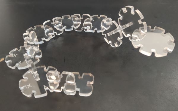
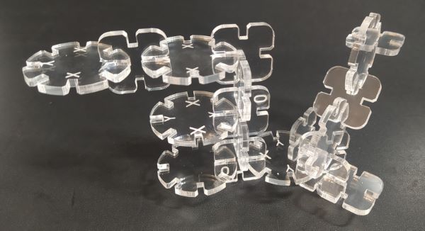
I spent quite a lot of time just fine tuning the parameters and making test cuts. After I had measured the kerf in acrylic, I only adjusted the thickness of the part in parameters in fusion 360. I also changed the design to have more chamfer. It was quite hard to get a good fit because when I had perfect fit in Y-direction, fit in the X-direction was too tight. I was using some scrap piece for fine tuning and after I had good fit I realized that I didn't have enough room for the "production" run. So I had to change the acrylic sheet and of course the new scrap sheet was slightly thicker so I had to do the fine tuning again. On the left you can see that the new sheet was thicker and when I tried to force the parts together, even in the looser Y-direction, the acrylic formed cracks. This reminded me that I could have added some fillets or chamfers to distribute the load better. At the Fab Lab I thought that I got the fit pretty close but at the home when inspecting them in greater detail, I ended up with a too loose fit. You could still use the parts for building, here is a snake and some modern architecture.
If I had made this assignment out of cardboard, it would have been easier. Cardboard would have had some springeness and I could have used a bit too tight fit with chamfers and it would have worked great. I could have used MDF but handling the cut parts with the fine wood dust gives me allergies.
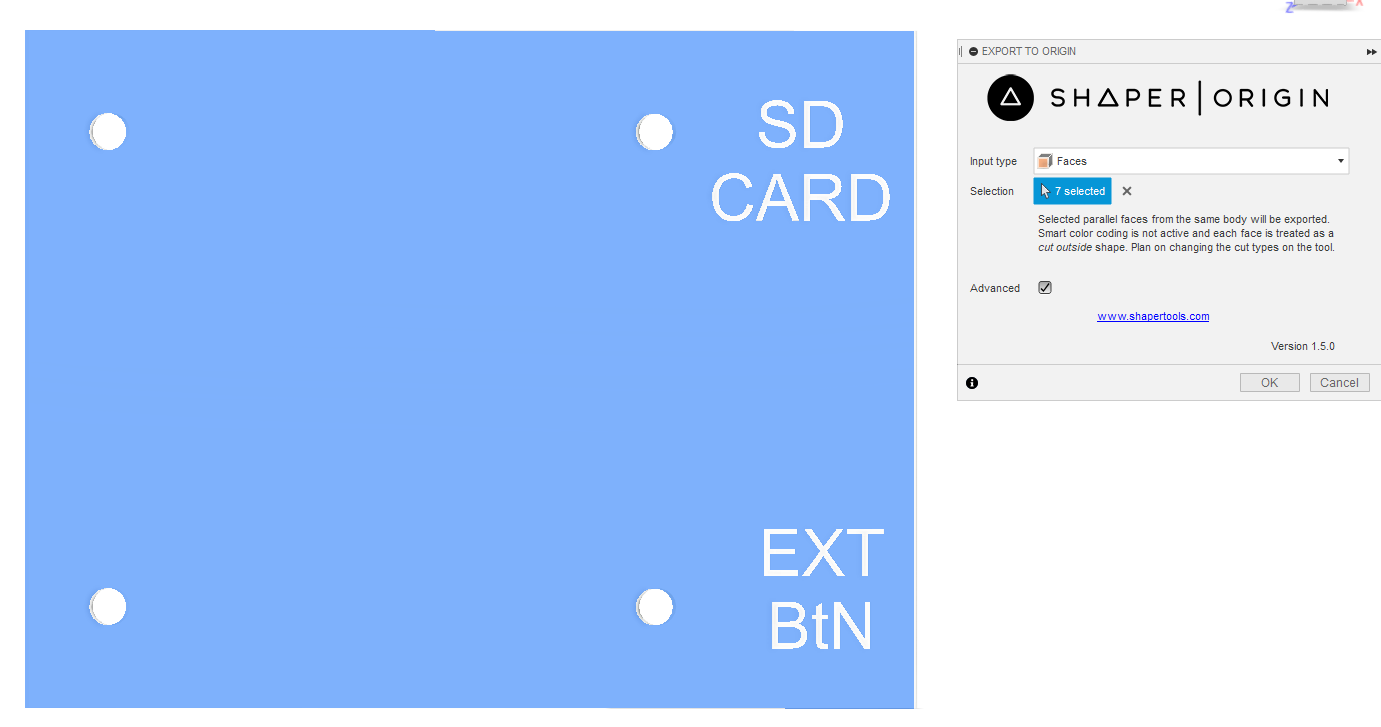
Shaper Utilities plugin for Fusion 360
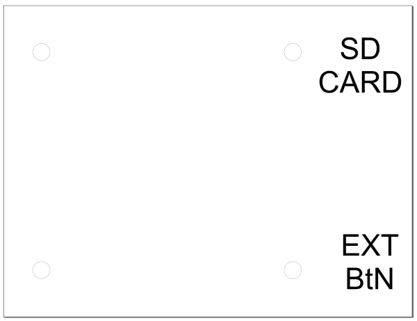
After exporting the cover as an SVG I had to set the correct stroke and fills in Inkscape for the laser cutter.
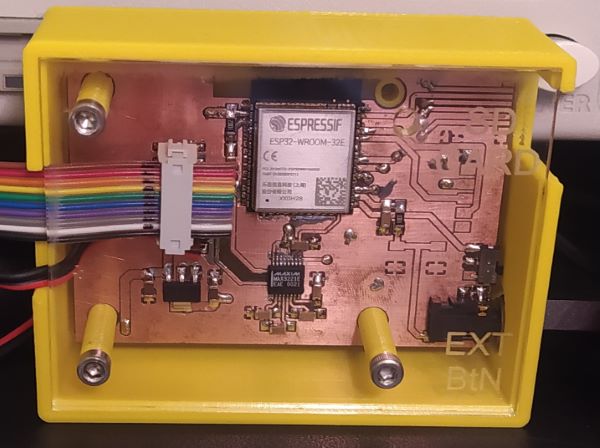
All the correct settings doneCover bolted to the case
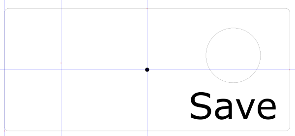
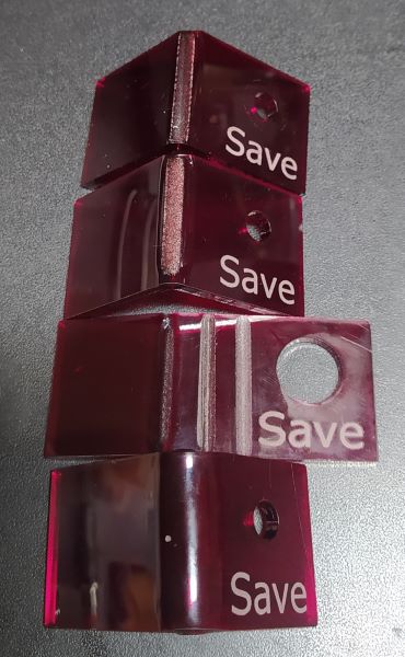
Button bracket in Inkscape
I made a quick bracket for the save button in Inkscape. I put a small engraved dot on the center of the piece so it would be easier to locate the center when bending the piece. Later I discovered that I had accidentally put diameter dimension in place of a radius for the hole.
Bottom is bended with heat gun. The rest are bended with laser, top one is the last one that I tried.
I wanted to bend the acrylic 90 degrees and I had seen Akseli Uunila using a heat gun to do the heating and bending. I heated the acrylic slowly and bended it in a vise with my fingers. The acrylic remained quite springy during bending witch meant that I had to over bend a bit to get the 90 degrees I wanted.
During the summer I had also told Akseli about LaserOrigami and he had tried. I wanted to try it myself and asked his advice. Sadly he didn't remember any of the settings he had used so I just started with the settings mentioned in the LaserOrigami website.
Slot
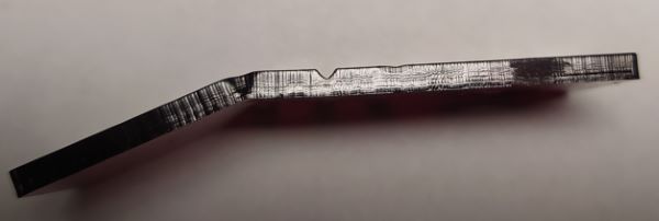
So I made a SVG file with a vector line and duplicated it 4 times, so I had 5 lines over each other. I used 30% power and 40% speed. I had the focus down about 4 cm. This was too much power and it cut a pretty deep slot. This slot was pretty nicely shaped as a V and could be used as a relief on the other side of the bend.
You can see from the photos above that I didn't quite get the setting completely right, there was still some boiling/over heating of the acrylic. In the end I used 30% speed and 10% power and I had 50 lines over each other and just stopped the machine when the piece looked like it could be bent by hand.
In the end I ended up using the piece that was bent with the heat gun but the LaserOrigami technique is worth a try in a future.
 On the laser you can jog the head close to the area you are going to work on by selecting the jog function and using the joystick to move the head. You can turn on the position laser on by clicking the red star thing on the control panel. By clicking the joystick, you set the new origin of the job. Then you can set the focus by using the focus tool and selecting the focus function. You put the focus tool on the laser head and you want to raise or lower the laser bed in a way that the focus tool is lightly touching the material. You can change the speed that the bed moves by flicking the joystick to the left, the speed is indicated by diamond symbols. Once you are happy with the focus height you confirm it by clicking the joystick. Now you can just check that exhaust and air is on and confirm that you are going to do the right job. Then just press GO and keep a close eye on the process in case there is problems.
 The vinyl cutter in Fab Lab Oulu is Roland CAMM-1 GS-24. When you start the vinyl cutter, you can select the material type, roll, edge or piece. Roll is obviusly the big roll, I think you can use two different widths of rolls. Edge detects only the width of the material while the piece option detects both, width and height. You can load the different materials in to the vinyl cutter by pushing the lever on the right. you need to adjust the rollers depending of the width of your material. The rollers need to be where white marks are on the top. After loading the material and adjusting the rollers you can close the rollers by pulling the lever. you can also adjust the origin in the X-direction while the rollers are open just by moving the cutting gantry and after that holding the origin button to set the new origin. I am not sure if you can adjust the origin in the Y-direction, I should have asked. (
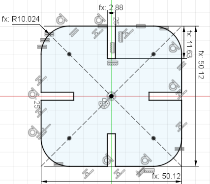

 After this I decided to use the offset tool to model the kerf. In the picture at right you can see that I made the original shape I want after laser cutting as construction lines. Here I made the the outline and made it 20 times bigger than it should so you could see the construction lines and the offset line at the same time. In the real design the
 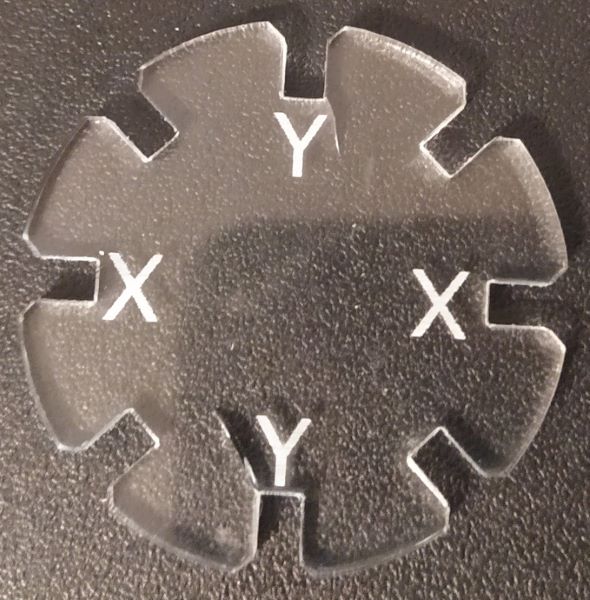 I spent quite a lot of time just fine tuning the parameters and making test cuts. After I had measured the kerf in acrylic, I only adjusted the thickness of the part in parameters in fusion 360. I also changed the design to have more chamfer. It was quite hard to get a good fit because when I had perfect fit in Y-direction, fit in the X-direction was too tight. I was using some scrap piece for fine tuning and after I had good fit I realized that I didn't have enough room for the "production" run. So I had to change the acrylic sheet and of course the new scrap sheet was slightly thicker so I had to do the fine tuning again. On the left you can see that the new sheet was thicker and when I tried to force the parts together, even in the looser Y-direction, the acrylic formed cracks. This reminded me that I could have added some fillets or chamfers to distribute the load better. At the Fab Lab I thought that I got the fit pretty close but at the home when inspecting them in greater detail, I ended up with a too loose fit. You could still use the parts for building, here is a snake and some modern architecture.
 If I had made this assignment out of cardboard, it would have been easier. Cardboard would have had some springeness and I could have used a bit too tight fit with chamfers and it would have worked great. I could have used MDF but handling the cut parts with the fine wood dust gives me allergies.