I did the group work with Toni Kyllönen and Joonas Patana. We connected three boards together, two were ATtiny412 boards, one with led and one without, and one was the ESP8266 board with it's led. The boards transmit signals were connected together and same with the receive signals. Then in the boards code the transmit pin was switched to input when ever the board wasn't trying to transmit. This was done so the transmit line wouldn't create a short circuit when other board would be transmitting. I modified the code slightly on my ESP8266 board so the leds state would toggle everytime the correct node would be called. Here is the slightly modified code that I got from our course's moodle page:
// Serial BUS example with switching Tx mode

// Orgianal code from our course's moodle page.
// I just added the ledState to toggle the led.

#include
#define txPin 1     // transmit signal to the bridge
#define rxPin 3     // recieves signal from bridge

SoftwareSerial mySerial(rxPin, txPin); // RX, TX

const char node = '3'; // network address
const int ledPin =  2; // the number of the LED pin
bool ledState = 0;

int incomingByte;

void setup() {
    mySerial.begin(9600);
    pinMode(ledPin, OUTPUT);
    pinMode(txPin, INPUT);
}

void loop() {
    if (mySerial.available() > 0) {
      digitalWrite(ledPin, LOW);
      delay(200);
      digitalWrite(ledPin, HIGH);
      delay(200);
      incomingByte = mySerial.read();
      if (incomingByte == node) {
        pinMode(txPin, OUTPUT); // open line to write
        mySerial.print("node ");
        mySerial.println(node);
        pinMode(txPin, INPUT);
        delay(200);
        ledState = !ledState;
        digitalWrite(ledPin, ledState);
      }
    }
}
We connected all the boards together using breadboard and connected an FTDI programmer to that so we could just use the Arduino's serial monitor to send and receive messages through serial.
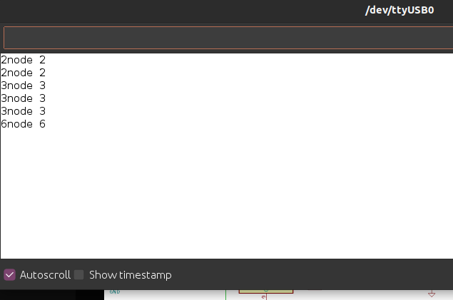
In the video you can see the ATtiny412 without the led on the left that acted just as a serial node, in the center is the ATtiny412 that toggled it led always when it's node address was received and in the right is the ESP8266 that flashes the led when there is a transmission coming from the serial and then toggles it's LED on or off if it's node address was called. The ESP8266 address was 3,the LED ATtiny was 6, and the ATtiny without the led was 2.
Arduino Serial Monitor. Repated nodes are not unwanted or unexcpeted action because, I pinged some nodes multiple times to see the expected actions.
We had only two weekdays to do this weeks individual assignment so it is very minimal. I used my desktop PC as TCP server and the ESP8266 board that I built in the input&output weeks as a TCP client. I was running MicroPython on the ESP8266 board, you can check the flashing here and the WiFi setup here.
I found this guide about sockets for Python. I used the echo server code from there, but modified the host address and port. I also changed the response that the server sends to client a bit.
# https://realpython.com/python-sockets/#echo-server

import socket

HOST = '192.168.1.101'  # Standard loopback interface address (localhost)
PORT = 8000             # Port to listen on (non-privileged ports are > 1023)

with socket.socket(socket.AF_INET, socket.SOCK_STREAM) as s:
    s.bind((HOST, PORT))
    s.listen()
    conn, addr = s.accept()
    with conn:
        print('Connected by', addr)
        while True:
            data = conn.recv(1024)
            print(str(data, 'utf8'))
            if not data:
                break
            conn.sendall(b'Hi from PC! I received: ' + data)
I thought that I would just try and use the echo client code meant for regular python in MicroPython. The client code was also from the guide linked above. The line:
with socket.socket(socket.AF_INET, socket.SOCK_STREAM) as s:
wasn't working in MicroPython so I modified the code and changed the messages a bit.
# https://realpython.com/python-sockets/#echo-client

import socket

HOST = '192.168.1.101'  # The server's hostname or IP address
PORT = 8000             # The port used by the server

s = socket.socket(socket.AF_INET, socket.SOCK_STREAM)
try:
    s.connect((HOST, PORT))
    s.sendall(b'Hello from ESP')
    data = s.recv(1024)
finally:
    print('Received ', str(data, 'utf8'))
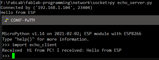
The with ... as method would handle also closing the socket correctly and I don't think that my version does this so it would need further research. Now I could run poth codes and the server on the PC would display the IP address of the ESP8266 that connected to my socket.
At the top of the picture: echo_server.py running on PC's command line
At the bottom of the picture: echo_client running on ESP8266 board controlled in PuTTY
In micropython I made an UART test and used the information from micropython docs to initilise it in UART1. During the testing I noticed that the UART1 was still putting out some junk so I changed it to UART2.
import time
from machine import UART

uart2 = UART(2, baudrate=9600, tx=17, rx=16, bits=8, parity=None, stop=1)

while True:
	uart2.write('test')
	time.sleep(1)
I tested the UART just by connecting the correct pins to the FTDI programmer and used PuTTY to monitor it.
I had already installed Mosquitto MQTT broker to my Raspberry pi but it can be simply installed with sudo apt install mosquitto mosquitto-clients and you need to set it to auto start on boot sudo systemctl enable mosquitto.service. You also might want to config the default port and allow anonymous access. To do this just add
listener 1883
allow_anonymous true
to file /etc/mosquitto/mosquitto.conf
I got the MQTT micropython example from micropython github and modified the server to match my MQTT brokers address. Since I had a device that was publishing temperature to topic named lampo, I subsribed to that topic.
import time
from umqtt.simple import MQTTClient

# Publish test messages e.g. with:
# mosquitto_pub -t foo_topic -m hello

# Received messages from subscriptions will be delivered to this callback
def sub_cb(topic, msg):
	print((topic, msg))


def main(server="192.168.1.108"):
	c = MQTTClient("umqtt_client", server)
	c.set_callback(sub_cb)
	c.connect()
	c.subscribe(b"lampo")
	while True:
		if True:
			# Blocking wait for message
			c.wait_msg()
		else:
			# Non-blocking wait for message
			c.check_msg()
			# Then need to sleep to avoid 100% CPU usage (in a real
			# app other useful actions would be performed instead)
			time.sleep(1)

	c.disconnect()


if __name__ == "__main__":
	main()
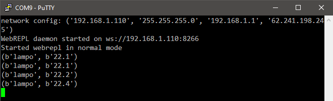
Result in REPL
After running the code I could see that the subscribing was working.
import time
from umqtt.simple import MQTTClient
from machine import UART
device = '54622D'
topic = bytes(f"{device}/raw_in", 'utf8')
server = '192.168.1.108'
client = device
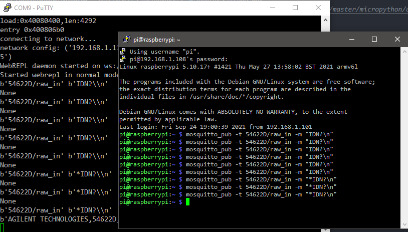
uart2 = UART(2, baudrate=9600, tx=17, rx=16, bits=8, parity=None, stop=1, txbuf=0)
def sub_cb(topic, msg):
print(topic, msg)
uart2.write(msg.decode('utf8').replace('\\n', '\n'))
uart_wait(uart2)
answer = uart2.readline()
print(answer)
def uart_wait(uart):
for i in range(5):
if uart.any() != 0:
break
time.sleep(0.02)
def main():
mqtt = MQTTClient(client, server)
mqtt.set_callback(sub_cb)
mqtt.connect()
mqtt.subscribe(topic)
while True:
# Non-blocking wait for message
mqtt.check_msg()
# Then need to sleep to avoid 100% CPU usage (in a real
# app other useful actions would be performed instead)
time.sleep(1)
if __name__ == "__main__":
main()