First version with vroom module
I designed a first version of the breakout board using the ESP8266 module that was in the Fab Lab library in KiCad. That module was also listed in the Fab Lab Inventory. I milled it with the LPKF and the results of that machine were amazing. But then I picked the ESP8266 module and noticed it had different layout than the module that I had used in the first design. So I had to redesign the breakout board.
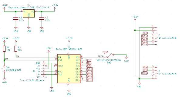
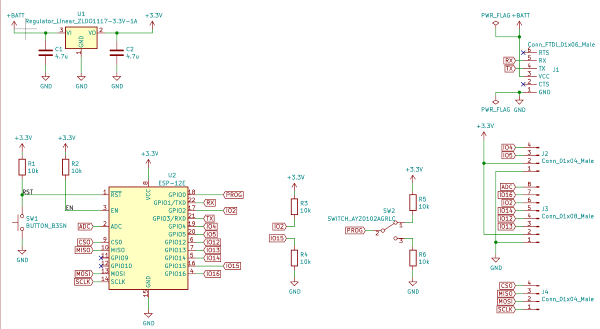
Schematic with the correct module
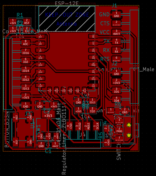
The pad layout suggested that it is some type of ESP-12 module. I think it is ESP-12E and that is what I used for it in KiCad. I/O 2 needs to be pulled high and I/O 15 at the boot of the module. When I/O 0 is low, the module is in programming mode and when it is high, module is in running mode. I got this information from the datasheet. I wanted both I/O connectors J2 and J3 have power and ground on the same spot so I could just plug new boards on both sides. I left I/O 9 and 10 unconnected because originally I didn't want to run any signals between the modules pads. They also don't work like regular I/O pins. I/O 10 is high for a few seconds at boot and using I/O 9 is not recommended at all.PCB layout
I am sure that I read from some datasheet that I/O pins 14 and 2 would be the default I2C SCL and SDA pins. I wanted those pins to be next to each other, so that's why the I/O pin 2 runs under the module. They weren't the default ones but that isn't a real problem since ESP8266 doesn't even have a hardware I2C. It just bit bangs I2C so you can use any I/O pin you want. I thought about adding a separate power connector but removed it when I couldn't really find free space for it in the board. I can still power it straight from FTDI if needed. It would have been easier to design the pin count for all the connectors to be multiple of three because I could only find 1x3 female pin headers in the fab lab. The FTDI connector is also a bit too close to the smaller I/O connector. I can still use both connectors at the same time but I think I can't use two boards right next to each other.
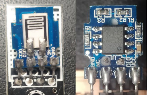
Both sides of opened DHT11 sensor
I chose DHT11 temperature and humidity sensor as my input device because in the networking week I'm planning to use MQTT to control electric plug based on the humidity in my room. I knew that DHT11 were easy to use and have plenty of ready made libraries. If I had a free choice I would have picked a DHT22 which has better range and a accuracy in both, humidity and temperature. According to Adafruit DHT11 has 20-80% range and 5% accuracy in humidity and 0-50℃ range and ±2℃ accuracy in temperature. Sampling rate is 1 Hz but I have read that you can sample faster but then the accuracy isn't guaranteed.
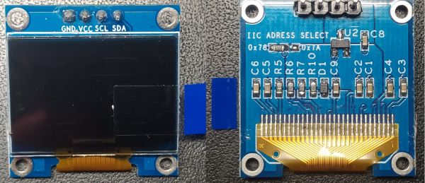
Both sides of OLED board
For the output I chose an OLED screen with I2C interface. It has 128x64 pixels and the size is 0.96". The first 16 rows of the screen are yellow and the rest are blue. The screen uses SSD1306 as an OLED controller and this version of the screen uses I2C for it's interface. You can change the I2C address of the screen by changing the position of an resistor in the back of the board.
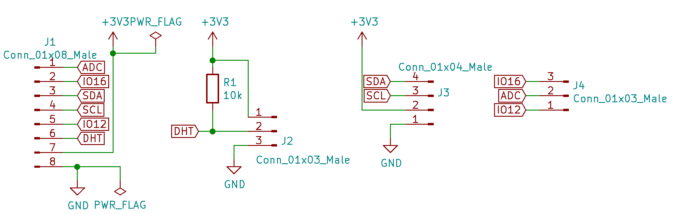
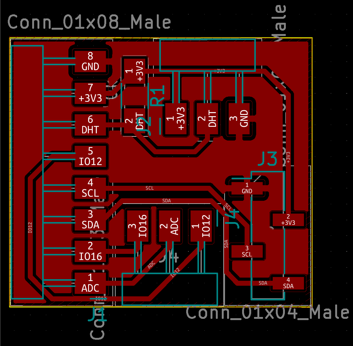
Schematic of daughterboard
Daughterboard just had a pull-up resistor for DHT11 temperature and humidity sensor, and connector for I2C OLED display. I also added a connector for the unused pins.
The display had four pin male connector so I wanted to use a vertical female connector on the daughterboard. I used PinHeader_1x04_P2.54mm_Vertical_SMD_Pin1Left as a footprint for the female connector but fab lab had PinHeader_1x04_P2.54mm_Vertical_SMD_Pin1Right as a component. I was able to use a 5 pin connector instead.
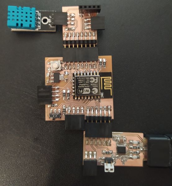
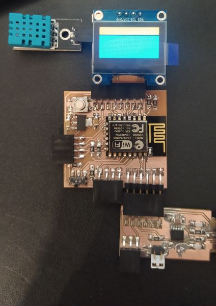
Assembled boards and DHT11
I used the LPKF ProtoMat S62 circuit board milling machine to mill the boards. This time soldering the boards was pretty easy since there weren't any really small components. The first time I powered the ESP board I decided to use the lab power supply so I could limit the current. I did this incase there were something wrong with the board. I set the voltage of the supply to 5 V and limited the current to 100 mA but this wasn't enough current for the boot up process. 200 mA was and when the board was done booting it draw around 70 mA current.
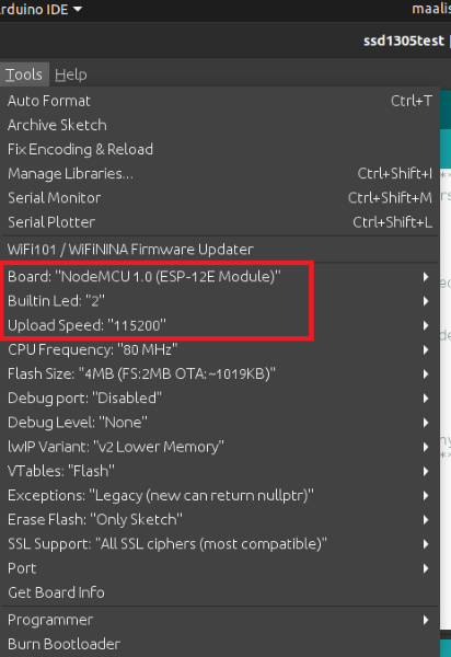
Arduino settings
After assembling the boards I programmed the ESP with Arduino IDE and run the default blink controlling the modules built in LED to confirm that I was able to program and run code on the board. After this I tried to run the Adafruit examples for the OLED but I had downloaded SSD1305 library and not the SSD1306 library. After I downloaded the correct library I noticed that I would need to change the I2C pins in the library files. At this point, I just went home and flashed the MicroPython in to it.
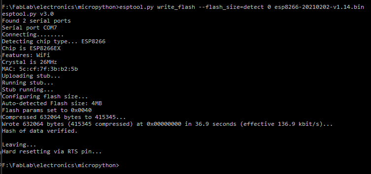
Flashing was claims to be successful
Flashing was successful but when I connected to the ESP8266 via serial, it only sent me junk. It sent different junk depending whether my switch was on the programming or running mode. First I thought that I just had the wrong baud rate and checked that I had the 115200 baud rate that the firmware should have. I tried the other common baud rate 9600 but that didn't work either. I found a solution in the MicroPython forums. I copied the command there and it worked.
At the time I thought that I had the same problem that the forum user had which was that the flash size was wrong. But you can see from the picture above that the flash size was detected correctly. Now I have read that the flash mode had to be dio for the ESP-12E module.
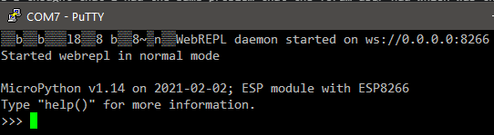
REPL in PuTTY
Now that I had correctly flashed the ESP8266 I could see the REPL, which is like MicroPython shell, prompt in PuTTY.
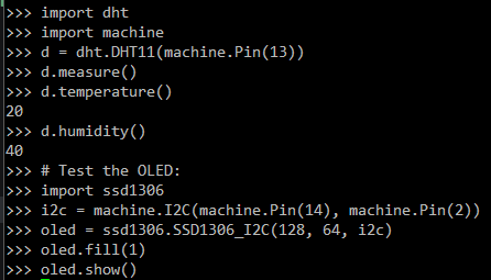
I used the MicroPython documentation to get the DHT11 measurements in REPL. I followed this tutorial to get the display working. I think the OLED library scans the devices connected in the I2C since I don't need to give the device address anywhere.
Every pixel on OLED display
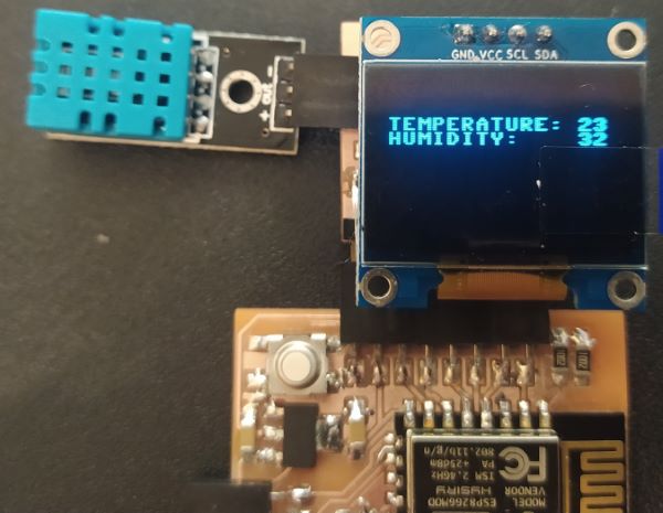
After this I made a quick program that displays the measurements on the display.
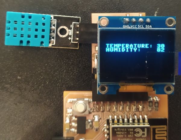
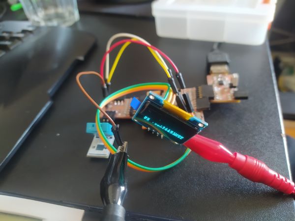
OLED showing the temperature and humidity measured by DHT11Temperature and humidity after a hot breath
Since I made a mistake in the default I2C pins the SDA is now also connected to the internal LED so every time I write something to the bus the LED blinks. This could be useful for debugging but right now it's just annoying.
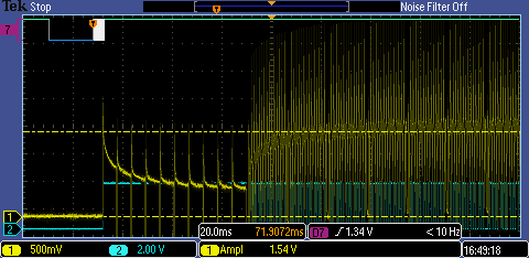
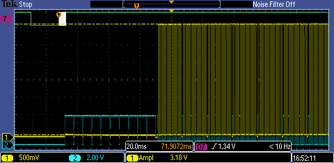
Data transmission (top, channel 7), ends right when the next measurement starts (channels 1 and 2)
When inspecting the signals in the DHT11 I noticed that when you request a measurement from DHT11 it sends the old measurement results back and then takes a new measurement. I used the Tektronix MSO 2002B mixed signal oscilloscope to check the digital and analog signals.
Analog signalsHumidity sensors legs on the left. I had probes in both legs in channel 1 and 2 in the oscilloscope. I think R3 in the right picture is the thermistor just based on the fact that it doesn't have a value written in to it.
I put the oscilloscopes probes in the both legs of the humidity sensor inside the DHT11 and checked what was happening there.
Humidity sensors legs in low humidity. Amplitude was 3.18 VHumidity sensors legs in high humidity. Amplitude was 1.54 V and maybe still climbing
I don't really know what is happening here but my guess is that the DHT11 is measuring the capacitance of the humidity sensor by charging it and measuring the time it takes to charge or the voltage it has reached after certain time.
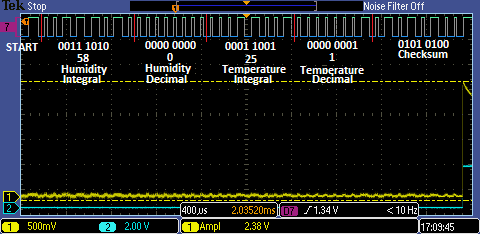
Digital signalsPart of the DHT11 one-wire signal. handshaking from the start is missing. Manual decoding results were the same that I got from the ESP
From the DHT11 datasheet I figured the format that DHT11 uses for the data after the handshaking and decoded two different results. I was wondering why I only got integer value using the MicroPython library and for DHT11 it only uses the integer values.
The checksum is calculated just by adding every bit together so from the picture above:
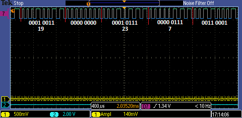
0011 1010 + 0000 0000 + 0001 1001 + 0000 0001 = 0101 0100Digital signal in lower temperature and humidity
Current measurement
I used jumper wires so I could measure the current going through the OLED displays ground pin. When the screen was fully lit and the contrast was the highest, it drew 22.1 mA at 3.313 V. So the power consumption were ~73 mW. When I was just displaying the the two lines with temperature and humidity, it drew around 1 mA current so around 3 mW power. I used the Aneng AN8009 multimeter for the measurements.
 Daughterboard just had a pull-up resistor for DHT11 temperature and humidity sensor, and connector for I2C OLED display. I also added a connector for the unused pins.
 I used the MicroPython documentation to get the DHT11 measurements in REPL. I followed this tutorial to get the display working. I think the OLED library scans the devices connected in the I2C since I don't need to give the device address anywhere.