I did this weeks group work with Toni Kyllönen and Joonas Patana, our instructor was Mikko Toivonen.
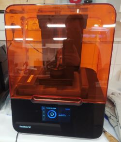
Fab Lab Oulu has different 3D printers and each one of them have different properties. That's why it's good to know some of these properties when designing 3D printed parts or when you are choosing which printer to use. To test the printers we used thingiverse user's ctrlV Test your 3D printer! v3 test.
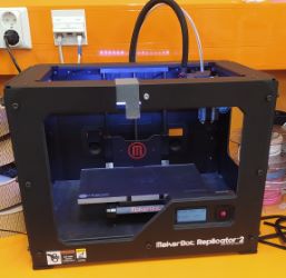
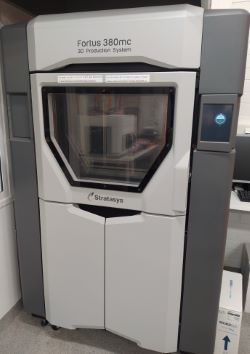
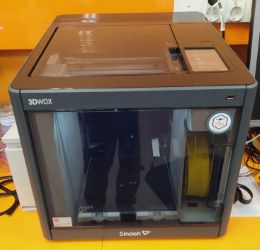
MakerBot Replicator2 uses PLA as a printing material and we used a brim to get it to stick better. Sindoh 3DWOX DP200 uses PLA as well and we didn't need a raft or brim for this machine. Stratasys Fortus 380mc uses ABS for printing and PLA for supports and with default profile it used a raft for the print. Formlabs Form 3 uses resin and according to the sticker in vat the resin was tough 1500. With Formlabs we used a raft and supports to lift the part from the printing bed. Supports from the warp and bridge tests were removed to keep the test somewhat equal.
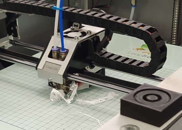
We were also going to use the Leapfrog Creatr HS but when Mikko homed the machine remotely from OctoPrint there was a spatula right under the nozzle. Joonas heard the missed steps noises that the printer was making and notified Mikko. Mikko got the spatula out of the printer, homed it again and started the print.
Failed print after spatula crash
After a while the print wasn't stuck on the printing bed. I thought that the spatula might have pushed the printing nozzle but Mikko said that the bed was probably misaligned.
Formalabs print is still uncured and covered in IPA which might smooth out the surfaces in pictures. I think we would have had the fully cured part at the end of the day if we would have started with formlabs, like me and Toni tried to suggest.
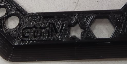
The star and nut look pretty decent but the surface finish is terrible.
The nut hole is really rounded.
Text has a thin bottom layer.
Everything looks really good.
Spike, pyramid and concave
Just a square hole where the pyramid should be, nothing else printed.
Rounded concave print looks a bit rough. The spike was longer before we separated the print from build platform. I think it was almost as tall as sindoh's. Toni said that the spike was tall but had alignment problems.
Concave and pyramid features are smoother than in fortus's print. Top of the spike has long and pretty thick string all the way to the warp test.
Everything looks good. Spike is really sharp.
Overhang 25°-70° in 5° increments
Nothing printed.
The 65 and 70 degree test have thicker bottom side.
Top corner of the pillar is messed up in every test.
Looked good
Warp
Nothing printed.
Looks good.
Has a bit of surface roughness on both sides from stringing.
Looks good.
Hole in the wall and Z-height 0.1-1.1 mm in 0.1 mm increments
Apart from the surface finish the Z-height looks surprisingly good. Wall didn't print.
5 of the 11 Z-heights visible. Overhang of the whole was too much.
5, maybe 6, of the 11 Z-heights visible. Helo in the wall is pretty clear.
Can't tell from the picture because of the IPA smoothing the surface and I don't have the part at hand but I think all Z-heights were printed. Hole in the wall looks smooth.
Bridge 2, 4, 8, 16 mm apart and 3D optimized font
Markings looks better than sindoh or fortus. Nothing else printed.
Bridges are narrow and have lot of stringing. 16 mm bridge is drooping. 8 and 16 markings are unreadable, 8 looks like 6 and 6 looks wonky.
8 mm bridge has small drooping. One of the pillars has couple of really thick strings stuck to it. 16 is unreadable.
16 mm bridge is drooping. Markings look good.
Wall thickness 0.7-0.1 mm in 0.1 mm increments and wave
Wave looks pretty good. Walls not printed.
Only 0.7-0.5 mm walls printed. Wave looks good.
0.7-0.5 mm walls printed but they have lot of layer mismatching. Wave also has a tiny amount of mismatch.
All the walls printed. Wave looks good.
Minimum distance 0.7-0.1 mm in 0.1 mm increments, holes, spehere and text
Minimum distance is really good. 0.3mm gap is clearly separated and 0.2 allows a light to come through.
0.5 mm gap is the smallest one. Sphere and holes are pretty good.
0.5 mm gap is the true smallest gap but elephants footing ruined the smaller gaps, maybe fiaxable with raft? Holes are rougher than in fortus' print. Spehere has piece of filement stuck on top of it.
Minimum gap is suprsingly only average 0.5 mm. Sphere and holes look really smooth.
In photogrammetry you take multiple photos of an object you want to scan from different angles. Then you pass these photos to program that tries to stitch these photos together and calculate the objects shape.
I had done photogrammetry years ago just for fun so I thought I could just jump in head first. I remembered that I used my record player as a lazy susan for the object that I tried to make 3D scan out of. So I setup it for that again and got every easily movable light and bounced them from the walls and roof to get a somewhat even lighting. I used Nikon D90 with a 35 mm objective and used a pretty narrow aperture so I would get a decent depth of field. I took 33 photos total. The camera was mounted to tripod and I would spin the turntable about 30-40 degrees between shots. After full rotation I raised the tripod so I would get a better angle for the top of the object. Lastly I lowered the tripod to get images from a lower angle.Example image from the data set
I installed Autodesk Recap and made a new project chose photo to 3D, then from the Create 3D menu I chose Object. Then I just selected the images and clicked start. After a while the software had uploaded all the pictures and the job was stuck in the queue. After a couple of hours the job status was still "1% Waiting in queue" and after some googling I discovered that EDU licenses has the lowest priorities in the queue so it could take a long time before the job would be processed.
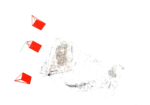
I wanted to look at options that would allow me to do the calculations locally so I went to our courses moodle page and checked the options there. First one that I saw was COLMAP so I downloaded it and checked their quickstart tutorial. I started the GUI with the COLMAP.bat from Reconstruction menu I chose Automatic Reconstruction. There I defined Workspace folder and Image folder. Image folder was the folder where the images of the object were. Then I just hit run and waited. After maybe hour or two the COLMAP was done and this was the result:
Point cloud in COLMAP
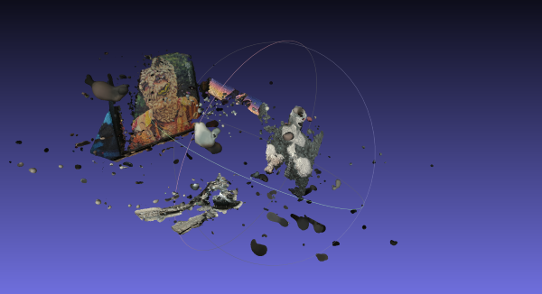
I could see the maggot man on the left and Draama-Helmi on the rigth. I could also see that the camera positions marked red seemed correct. What I couldn't see was the helmet that I tried to scan. I downloaded MeshLab hoping that maybe I could see the helmet there. I imported the COLMAP's output fused.ply from workspace\dense\0 folder to MeshLab and this was the result:
Point cloud in MeshLab
All the points in the turntable area were missing. This was a clue to me that the COLMAP was not expecting that I would rotate the object and not the camera. I took a look on the documentation again and it says "Capture images from different viewpoints. Do not take images from the same location by only rotating the camera, e.g., make a few steps after each shot.". I googled if there would be an fixed camera option but all the results were related to multiple fixed camera systems, not single fixed camera like I had. I also canceled the ReCap job.
New object
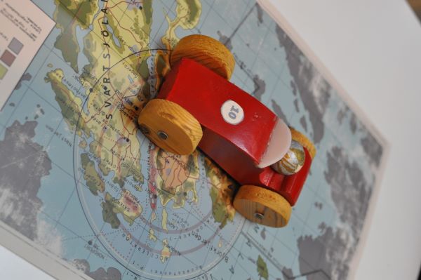
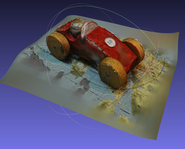
I read the tutorial linked in our course's moodle page and decided to change object and tactic. I placed a wooden car that I have made as kid on the map so that the stitching software would have something that it would recognize from different angles. I used the same camera and lens combo as before. Again, I turned every light I had on and tried to lit the object as evenly as possible. Apparently I took 35 pictures and uploaded them to ReCap. I decided to run the photos through COLMAP also while waiting the ReCap to finish. After the COLMAP was done I opened the .ply file in MeshLab and run Surface Reconstruction: Screened Poisson from Remeshing, Simplification and Reconstruction submenu from filters menu.
After surface reconstruction in MeshLabCar in ReCap. Pyramid shapes are some of the camera positions.
I had way better results in ReCap so I continued with it.
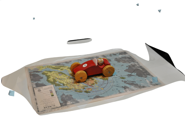
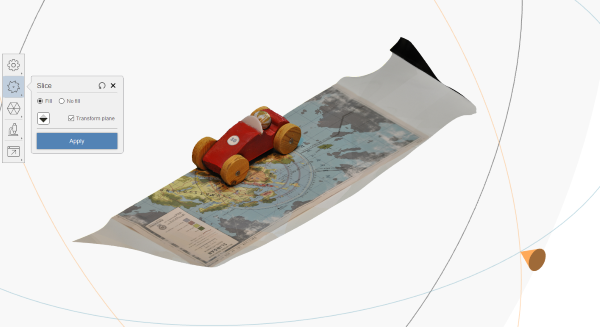
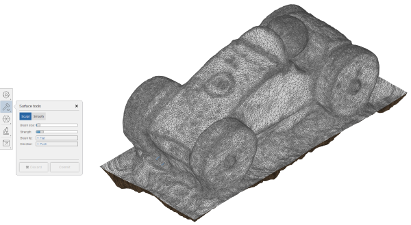
Slicing roughly around the carPushing the areas around car deeper so I could slice the ground away
I sliced roughly around the car and then pushed the surfaces around the car lower so I could slice the ground out. I would recommend to push the areas lower around the object first because in the order that I did it, the push tool didn't work on the edges of the ground.
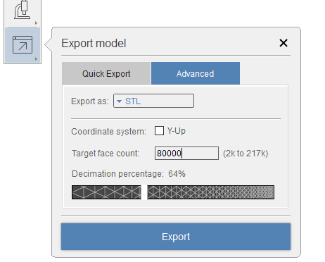
Exporting as STL and limiting the face count to compress the file
I exported the object as STL and without limiting the face count the file was around 10 MB so I limited the face count to 80000 to get file sized around 4 MB.
The bottom of the car wasn't succesful but I think the result is still good enough.
Usually what I think first is what would be the easiest thing that would fullfill the requirements in the assignment. I do that so I have a simple back up plan incase the thing that I want to do fails. This time the simplest thing would have been a coiled tube inside a block but that would have been incredibly boring and would almost need a transparent print material.
I was thinking about doing some kind of ball joint. I browsed through Thingiverse and found these gyroscopic relaxing keyrings. First I thought that I would do just multiple nested spheres with pretty tight tolerances so you they would slide against each other smoothly. The group work showed that tight tolerances wouldn't work and that I would need at least 0.5 mm gap between walls. I decided that I would add two axels and make the middle sized sphere spin so it could be used to close the "box".
Creating spheres from sketch
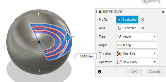
First I sketched three point archs. I defined three parameters: wallThickness, clearance, and diameter. Diameter would be the outer diameter of the largest sphere. All other archs dimension were defined by using these parameters. I used formulas to calculate the rest of the archs dimensions but I could have just spaced them with the clearance and wall thickness parameters. Then I just selected the correct profiles and used the revolve tool to revolve them 360 degrees.
Creating spheres from sketch
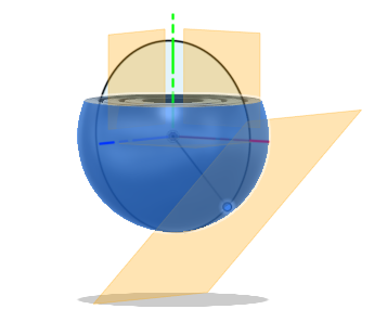
Then I made an offset plane and used that as a splitting tool with Split Body tool. I then removed the bodies that were on top of the sphere. Then I made a sketch so I would get a point on the surface of the sphere so I could make an Offset Plane and sketch there. I wanted this plane because I wanted to add some drain holes to the design. I wanted to use the resin printer to print this and I didn't want to trap resin between spheres. I wanted the drain holes in 45° angle because I thought that I would probably angle the print in that direction when printing.
Split bodies, sketch to make the offset plane and offset plane
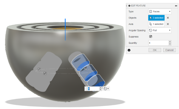
Now when I'm writing this, I know that I could have just used Plane At Angle tool and made the cut from inside to outside. When I was doing this I did use the method described and shown above. I made a sketch with circle on the offset plane and used it to cut the holes to the spheres. I used 2.5 mm drain holes as described in Form 3 Design Guide. (Needs registration to download. I got it from our courses moodle page.) Then I made Circular Pattern out of those and four groups of holes at 90° angles. I added an axel from the outer ball to the inner ball on both sides.
With middle ball not visible, you can see the axel
These hidden axels and the balls inside of balls makes the part impossible to manufacture with traditional subtractive methods.
Interactive 3D model. Select the middle sphere, then right click and hide selected to see the hidden axel.
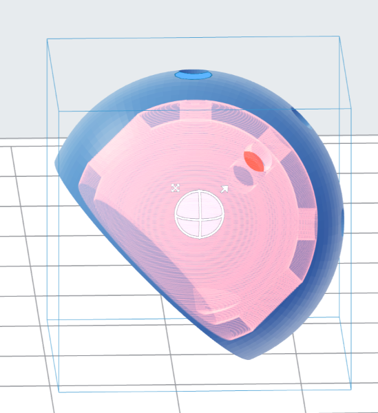
I loaded the modeil to PreForm and positioned the ball to 45 degree angle.
45 degree orientation
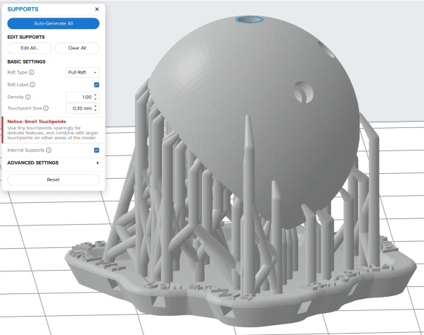
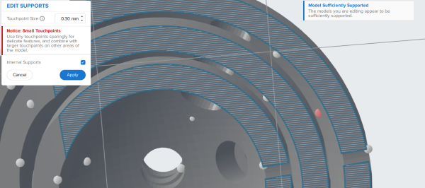
I used auto-generate to make the supports and then edited them and removed the supports between the balls by just clicking them in the editing mode.
Auto-Generated supportsRemoving supports by just clicking them
I sent the job to the Formlabs Form 3 and started the print. After the print had finished, I took the build plate out of the machine and put it in the Form Wash filled with IPA for 20 minutes. After that I pried it of from the build plate and let it dry. When it was dry I put it in the Form Cure for 60 minutes in 65 degrees. After that I ripped the supports off.
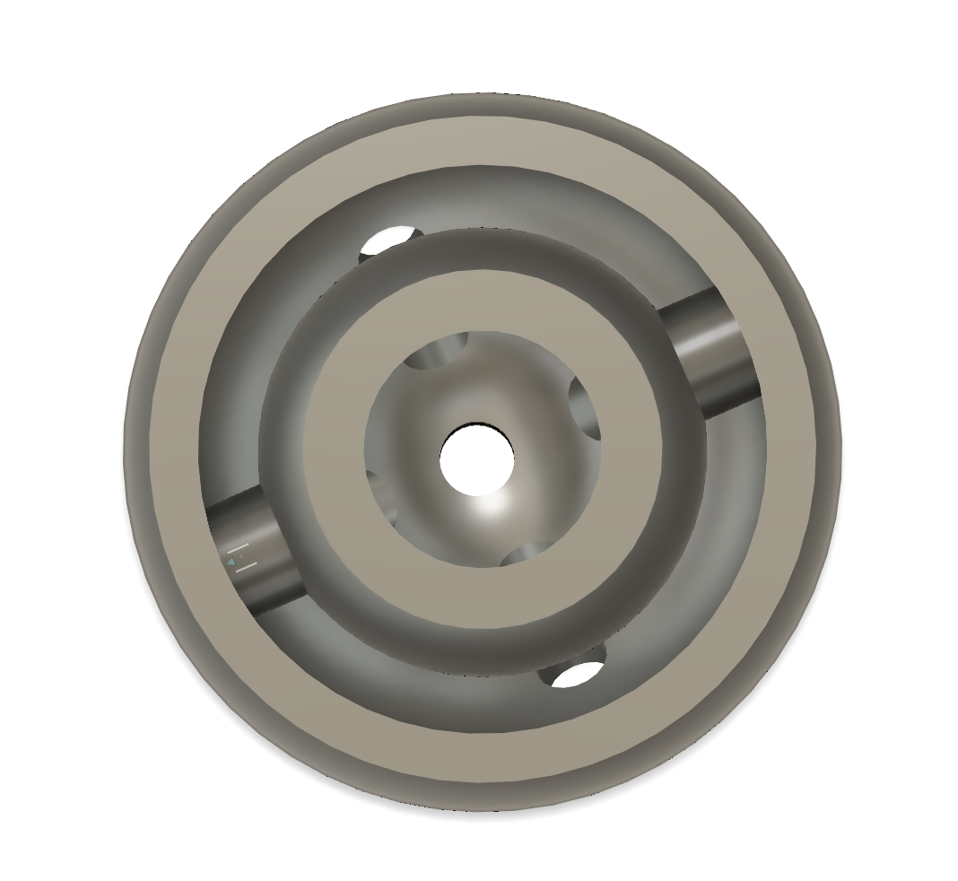
Supports removed
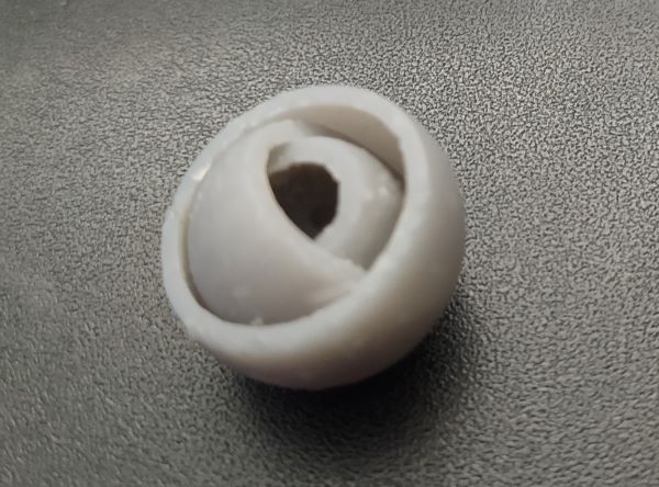
The middle sized ball was quite stuck on it's place but after careful prying I got it spinning.
Working print
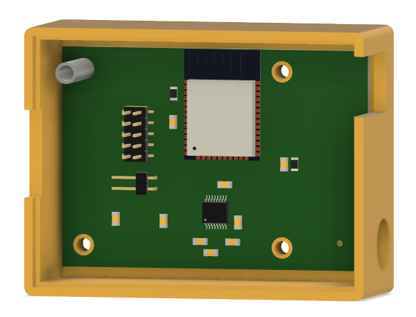
I wanted mostly 3D printed case so I could have some nice features implented directly to the case. I googled how to get KiCAD PCB model to the Fusion 360 and found this PCBWay blog post. So I just had to export the PCB as a STEP-file in KiCAD and import it to Fusion 360.
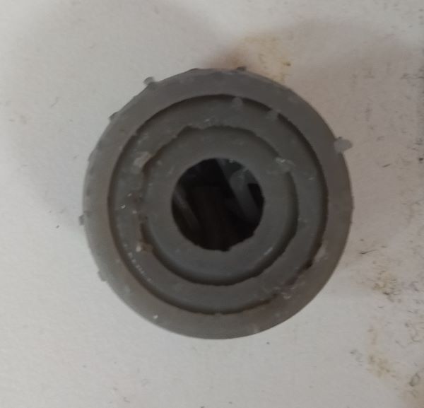
Case in yellow and spacer in grey
Then I just project the holes and PCB outline to the sketch and started extruding the bottom of the case, walls and the PCB standoffs. I made intendation to the top, so I could use 3 mm thick acrylic as a cover. I made some M3 sized pockets to the pack so they would be captive nuts. I downloaded the 3D model for the 2.5 mm jack from Digikey. I tried to use the align tool to align it to its place but every time I saved the file, the jack would jump back to zero. So I just measured it's hole location and made sketch so I could make a hole for the plug. I also made hole for the SD card so it could be removed easily by fingers. I added a slot so I could route the power and RS-232 wire through the cover and a case. I made just a tube as spacer to hold the PCB between the case and also modeled the cover in Fusion 360.
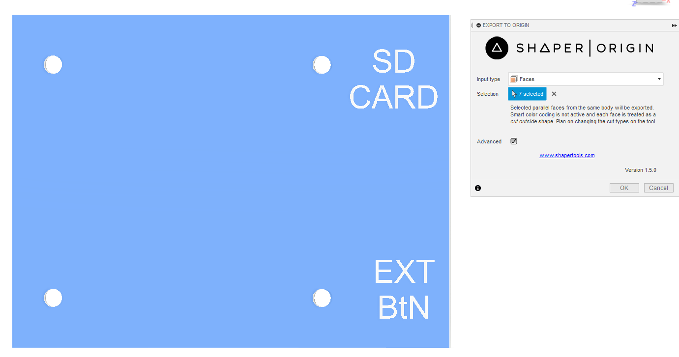
Shaper Utilities plugin for Fusion 360
I exported the case and the spacers as STL files. For the cover I used a plugin called Shaper Utilities. I heard about this from Toni Kyllönen. It allows you to export faces as an SVG. I had to modify the fills and strokes in Inkscape to get the result that I wanted.
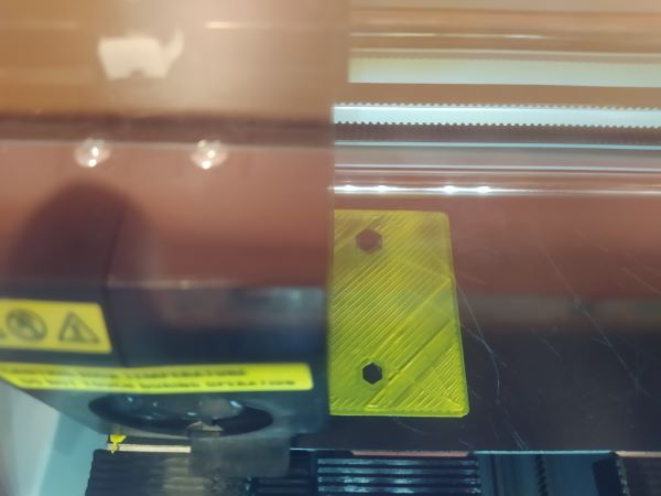
One of the nut layers didn't stick. Top and bottom holes should look the same.
I printed the case with Sindoh. At the start of the print I was bit worried because all the details in the first layer didn't stick to the printing platform. At the end the print was succesful and pretty decent looking.
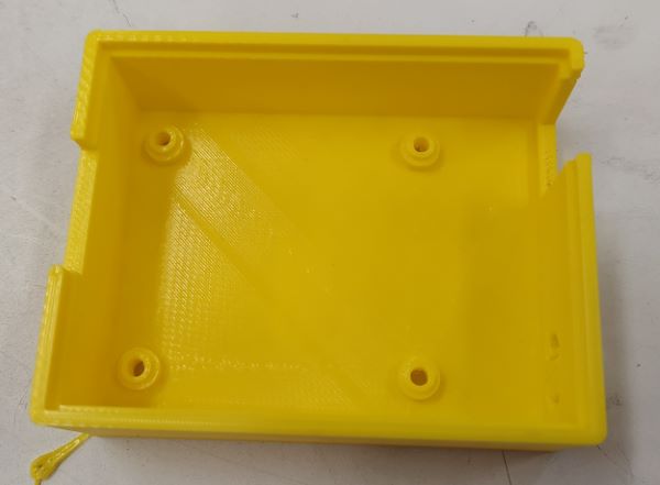
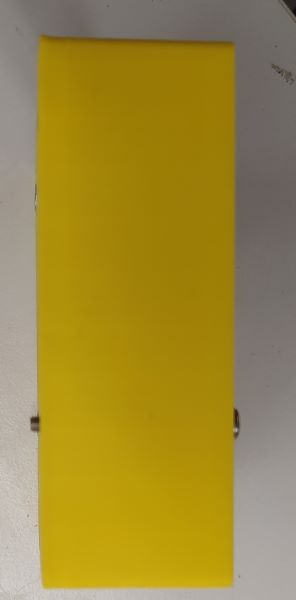
Printed caseBolt sticking out on the left
I should have made the case slightly taller so standard 30 mm bolt wouldn't have stuck out of the back of the case. Since this was mainly a cosmetic mistake and on the back of the case, I didn't bother to reprint the case.
 The star and nut look pretty decent but the surface finish is terrible.
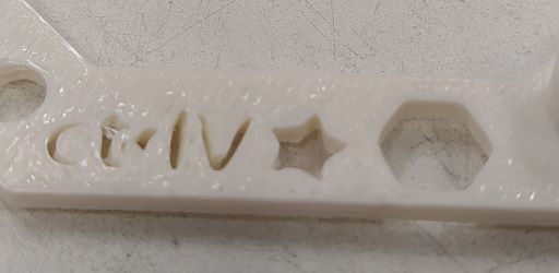 The nut hole is really rounded.
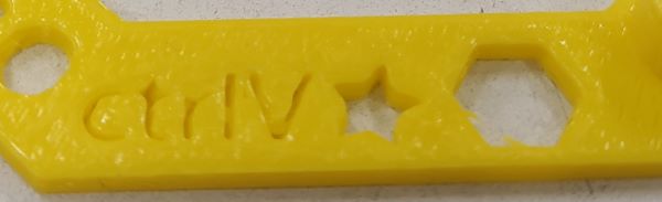 Text has a thin bottom layer.
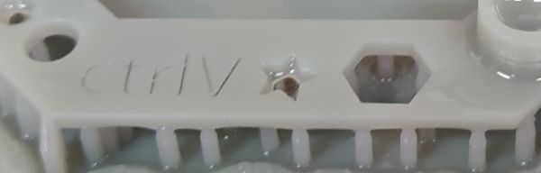 Everything looks really good.
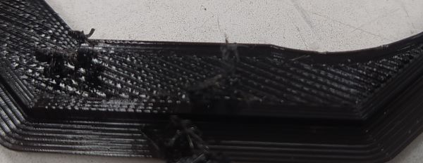 Just a square hole where the pyramid should be, nothing else printed.
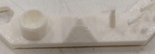 Rounded concave print looks a bit rough. The spike was longer before we separated the print from build platform. I think it was almost as tall as sindoh's. Toni said that the spike was tall but had alignment problems.
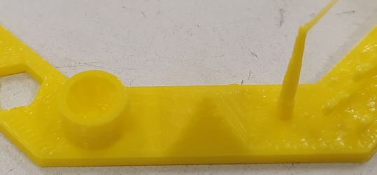 Concave and pyramid features are smoother than in fortus's print. Top of the spike has long and pretty thick string all the way to the warp test.
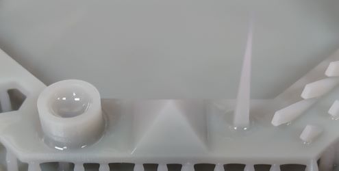 Everything looks good. Spike is really sharp.
 Nothing printed.
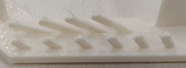 The 65 and 70 degree test have thicker bottom side.
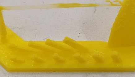 Top corner of the pillar is messed up in every test.
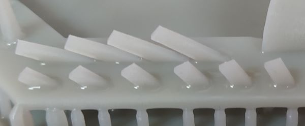 Looked good
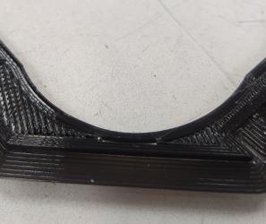 Nothing printed.
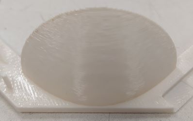 Looks good.
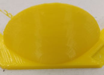 Has a bit of surface roughness on both sides from stringing.
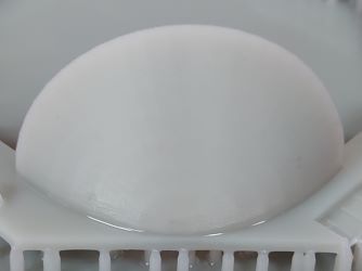 Looks good.
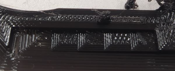 Apart from the surface finish the Z-height looks surprisingly good. Wall didn't print.
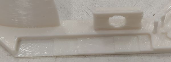 5 of the 11 Z-heights visible. Overhang of the whole was too much.
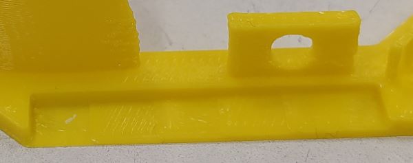 5, maybe 6, of the 11 Z-heights visible. Helo in the wall is pretty clear.
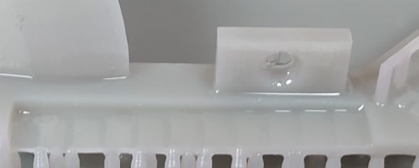 Can't tell from the picture because of the IPA smoothing the surface and I don't have the part at hand but I think all Z-heights were printed. Hole in the wall looks smooth.
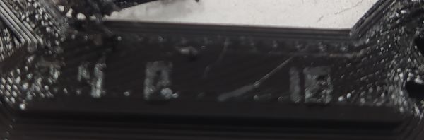 Markings looks better than sindoh or fortus. Nothing else printed.
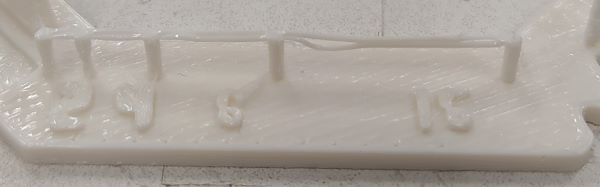 Bridges are narrow and have lot of stringing. 16 mm bridge is drooping. 8 and 16 markings are unreadable, 8 looks like 6 and 6 looks wonky.
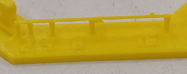 8 mm bridge has small drooping. One of the pillars has couple of really thick strings stuck to it. 16 is unreadable.
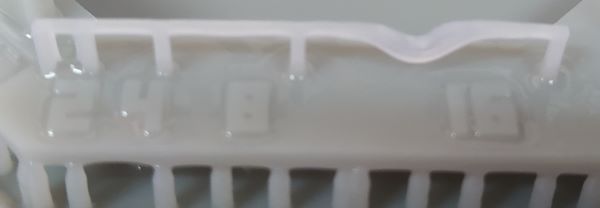 16 mm bridge is drooping. Markings look good.
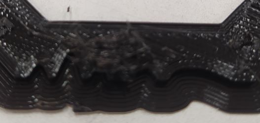 Wave looks pretty good. Walls not printed.
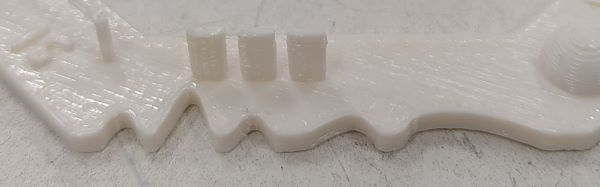 Only 0.7-0.5 mm walls printed. Wave looks good.
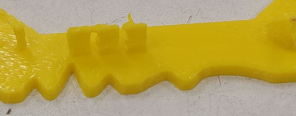 0.7-0.5 mm walls printed but they have lot of layer mismatching. Wave also has a tiny amount of mismatch.
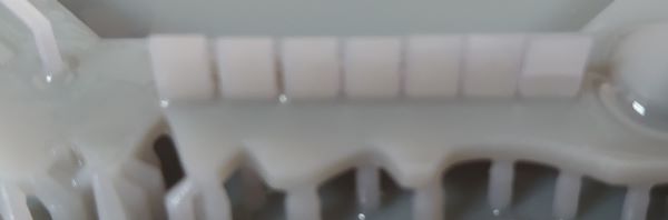 All the walls printed. Wave looks good.
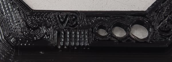 Minimum distance is really good. 0.3mm gap is clearly separated and 0.2 allows a light to come through.
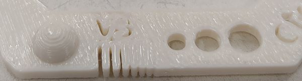 0.5 mm gap is the smallest one. Sphere and holes are pretty good.
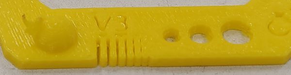 0.5 mm gap is the true smallest gap but elephants footing ruined the smaller gaps, maybe fiaxable with raft? Holes are rougher than in fortus' print. Spehere has piece of filement stuck on top of it.
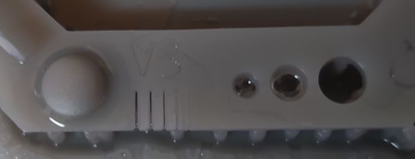 Minimum gap is suprsingly only average 0.5 mm. Sphere and holes look really smooth.
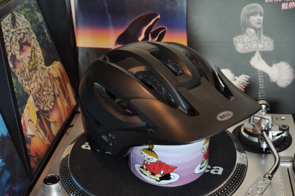