This idea might change to something else because this design is mostly made using 2D processes but I would like to learn more about 3D processes.
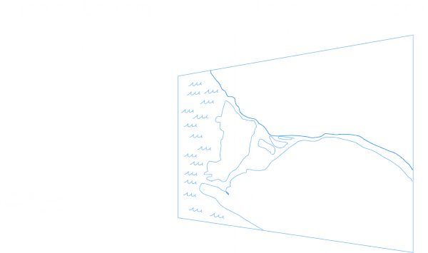
The first final project idea would be information display for myself. The actual and useful information would be time, date and weather forecast. The map in the background would mostly be just for art.
Layers one and two would be edge lit acrylic sheets. Layer one would have coastline and maybe some waves engraved.
Layer two would have engravings of roads and bike paths. Top or bottom layer would be LCD where the backlight and polarizing filter have been
removed so the LCD is "transparent".
Other ideas: Shower water meter and CNC
The second idea would be a shower water consumption meter that would measure the flow and temperature of the water and based on these calculate the total hot and cold water consumption and the price of the shower. This idea would also be used by myself.
Third idea would be some kind of CNC. I have built a pen plotter before out of electric waste but I would like to build and have a CNC that would be capable of cutting wood and maybe scratching aluminium. The precision parts are just bit too expensive for that kind of project because I don't have an actual use for that kind of machine. Laser engraver would also be an option but I live in one room apartment, so I think the fumes would always cause trouble. I'm also probably overly cautious about blinding myself.
Yet another idea: Wireless RS-232 controller for an old oscilloscope
I have an old oscilloscope and I would like to use the data from it. It only has floppy drive as a removable storage media. I don't have floppy disks or a drive in any of my computers so I haven't had a good way of storing data from the scope.
I would have an ESP8266 with a serial to RS-232 converter chip plugged in to the oscilloscope. ESP8266 would then be connected to my LAN. I would have some sort of GUI on my computer to get data from oscilloscope and control it. Right know I don't have a good idea about how would I handle the communication between the PC and the ESP8266. One problem is the baud rate, which is slow. When I don't have anything connected, the only baud rate that can be selected is 9600. The maximum baud rate of the oscilloscope is 57 600. The oscilloscope has 2 MB of memory per channel so to download it all would take quite some time.
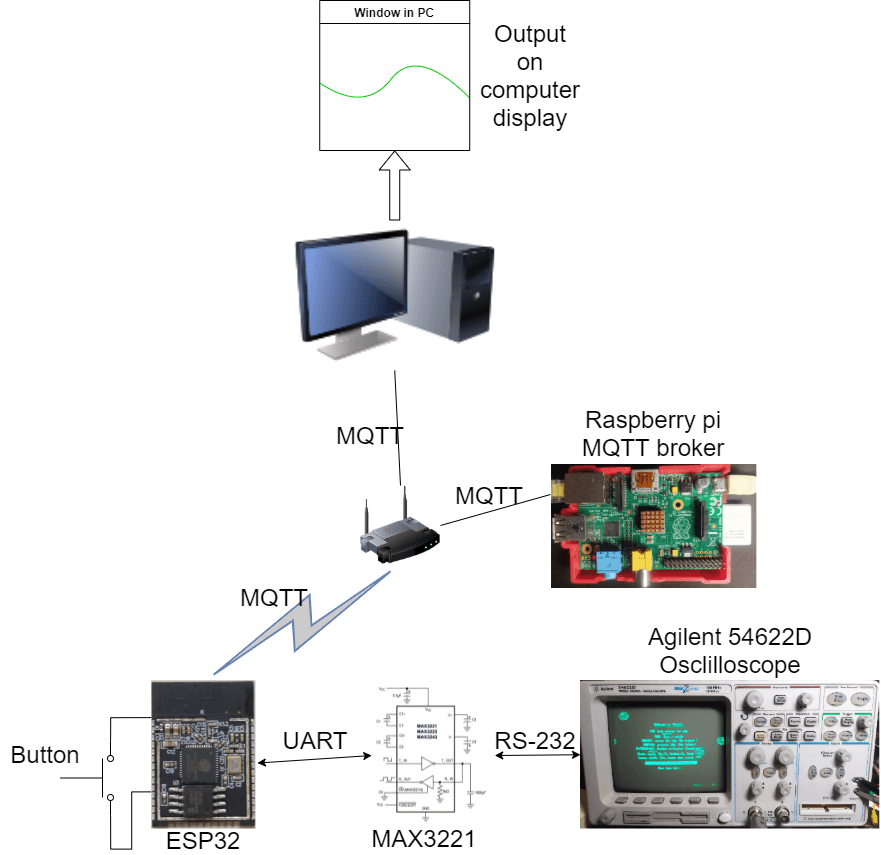
Idea is basically the same as "wireless RS-232 controller for an old oscilloscope" above. To do that I will use ESP32 that will send the data via MQTT protocol to the mosquitto MQTT broker that is running on a Raspberry Pi. ESP32 will take the data capture and send it when the button is pressed. I'm thinking I'm going to use one button press to capture channel 1 and two presses to capture channel 2. ESP32 will get the data from the oscilloscope by RS-232 port. ESP32 doesn't have RS-232 capabilities so I'm going to use MAX3221 converter to convert ESP32's UART to RS-232. To get the data from the oscilloscope I need to send some commands first to set up the capture. Luckily this process has been explained and well documented by Hammond Pearce.
When the data is captured I want to send the time datapoints to one MQTT topic named 54622D/time and voltage points to 54622D/voltage. With the PC I'm going to use python to make a program that subscribes to these topics and plots them.
I know that the programming is going to be the hardest part for me in this project so I wanted to quickly start coding and trying things out. I had made FTDI to RS-232 board so I could first test the communication directly between the oscilloscope and PC. I have described the project in more detail in the Applications and implications week.
I started the testing by by using an FTDI programmer and the FTDI to RS-232 board that I mentioned earlier. You can check how I got it working from here.
Quick demo of the remote control
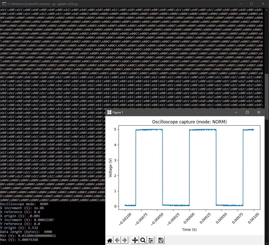
Testing the Hammond Pearce's code
I used the PC ↔ FTDI programmer ↔ FTDI to RS-232 board ↔ Oscilloscope hardware to test the Hammond Pearce's code. A tiny bit more information here.
I broke a pad connecting the DB9 connector to the FTDI to RS-232 board. I put too much strain on the board while messing around blindly behind the oscilloscope. This is something that I need to consider when designing the case.
I had quite a few problems while porting the code from python to micropython. More here. The largest one was the problem where I wasn't getting all the data points from the oscilloscope. In the end I circumvented the problem just by lowering the amount of the data points that I request from the oscilloscope. This lowers the quality of the graph a lot but atleast I have something to plot. I could also improve this in the future if I have time or outside of this project.
boot.py and main.py are running on the ESP32. boot.py just connects to wifi and main.py is the main program. main.py catches the button press and sends the data capture command to the oscilloscope, then it parses the received data (this data parsing is based on Hammond Pearces code) and sends it to a MQTT broker on Raspberry Pi. MQTT broker is commonly used Mosquitto.
plot.py is running on the PC and it subscribes to MQTT topics and plots the data that it receives. The MQTT part of the code is based on EMQX tutorial and the plotting is based on the Pyplot tutorial.
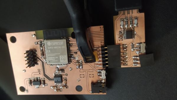
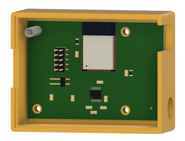
Since I had already made the FTDI to RS-232 board and tested it with a ESP32 dev board I only had to implement those and a button to single board but with ESP32 module. More here.
Assembled board
The biggest note during this phase was that I pivoted to simpler physical format, because I was bit behind my own schedule. I changed the design from one piece that would just stick out of the data connector to box that could be attached behind the scope and had some wires coming out of it to connect it to the oscilloscope. Doing just a rectangular PCB with wires, would allow me to make the case be just a simple box so I could catch up with my schedule during the case design phase.
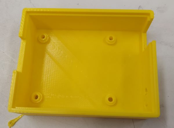
Case without the cover
I decided to 3D print part of the case so I would be able to design PCB stand-offs and captive nuts as a part of the case. More here.Printed case
I made a mistake designing the case because I didn't think the bolt length at all. Now standard 30 mm long bolts were just a few millimeters too long and stick out on the back. Since the mistake was only cosmetic and on the backside of the case that goes against oscilloscope I didn't fix this issue.
I designed the cover in fusion 360 and laser cut it. I just relied on the kerf to give me some tolerance so that the cover would fit pretty easily.
I designed a bracket for the save button on Inkscape. I accidentally put diameter dimension in the place of the radius so I got hole that was twice as big as it should and I only noticed it when the laser was already cutting the hole. So that piece became my test piece to test LaserOrigami techniques. It is pretty qreat and if I need to bend acrylic in to sharp corners I will use more time to fine tune the settings. Now I used a piece that was bent just by using a heat gun.
More here.
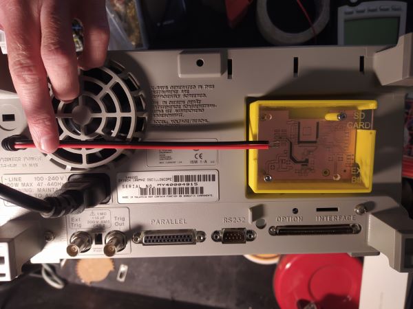
Just a bit too short wire
The power plugs wire was just a bit too short so I had to solder a small extension to it. Also the polarity of the plug is reversed from the standard but I had measured that just to be safe before connecting it to anything. Other wise assembly went smoothly.
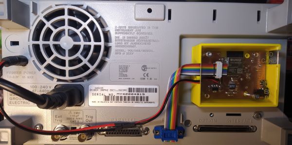
Checking how everything fits
I forgot to take enaugh bolts from fab lab and that's why even in the final photos and video case is missing one bolt.
The device works but there is room for major future upgrades. The most important part would be to get the full 2000 points to the ESP32. I am not sure why it didn't work, but there is atleast a chance that it could be fixed with just a software update. I also could solder the SD card socket and update the software to support that.
I'm pretty happy about the system integration. Because the device gets it power from the oscilloscope it seamleslly turns on and off with it. I also like how it is flat enough in the back of the oscilloscope without disturbing anything. I'm not happy with the Save button and its bracket, it is a bit crude.
Software could be better, but I haven't noticed any real bugs in it. The most annoyng thing in the current PC software is that you have to close the figure to make a new figure. This is pretty annoyng feature of matplotlib. I could have avoided it but then the figure window would stop responding and had to be closed forcefully.
This project was for my personal use so there aren't any great benefits for other people. I can now use the oscilloscope and the measurements I do with it better because I can store the data in my computer and analyze it better. I also know that this project helped my friend to do his own version to control a signal generator.
 Layers one and two would be edge lit acrylic sheets. Layer one would have coastline and maybe some waves engraved.
Layer two would have engravings of roads and bike paths. Top or bottom layer would be LCD where the backlight and polarizing filter have been
removed so the LCD is "transparent".
Layers one and two would be edge lit acrylic sheets. Layer one would have coastline and maybe some waves engraved.
Layer two would have engravings of roads and bike paths. Top or bottom layer would be LCD where the backlight and polarizing filter have been
removed so the LCD is "transparent".


 unless otherwise noted
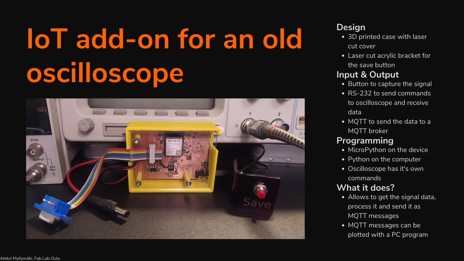