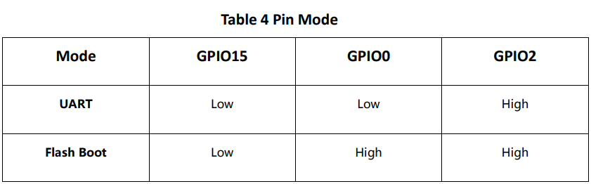
I have read the ESP-12E WiFi modules datasheet almost completely since it's only 18 pages. It had a very Chinese feel to it, for example the picture in the right is straight and uncompressed from the datasheet. I have used this to design my board in the input and output weeks. I read the pin configurations for the UART or Flash Boot modes, or as someone might say programming and running modes, from there.
Pin configuration for different modes
When designing the board, I also put the I2C pins (that are default ones in the datasheet) right next to each other on the female header connector that I was going to use for the display. Arduino uses different pins for the I2C and that caused me more work last week and this week.
I2C pins in the datasheet. I think Arduinos default pins are GPIO 4 and 5.
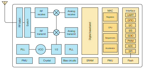
Functional block diagram of ESP8266EX
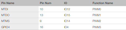
I also skimmed through the ESP8266EX datasheet. Most interesting information to me were the PWM pins and that the ADC has 10-bit precision. The ADC can be used to measure the power supply voltage (~3.3 V) internally but the range is only 0-1 V when it is used in external circuit. These measurements cannot be done at the same time.
PWM pins
ESP8266EX datasheet also pointed me to the Technical Reference where I could learn more about setting the pin registers and stuff like that.
I wanted to try MicroPython on this course since I wanted to try MQTT in the networking week and I have read that MicroPython would be a good way to implement it. I also just wanted to try something different than Arduino's C/C++ like language that I have used multiple times in the past. Raspberry Pi Pico came out this year and it has support for MicroPython. I don't have any plans to own one but when someone as big as Raspberry Pi does something, I want to know more about it. I think that's enough of me defending my choice of using a high-level language even though my main interests are in the hardware.
I followed the guide on MicroPython documentation to get the ESP8266 connected to my WiFi for the first time. Then I used the WebREPL to download the boot.py file and added the following function to it to always connect to my WiFi at boot. The function is from the same documentation as before.
def do_connect():
	import network
	sta_if = network.WLAN(network.STA_IF)
	ap_if = network.WLAN(network.AP_IF)
	ap_if.active(False)
	if not sta_if.isconnected():
		print('connecting to network...')
		sta_if.active(True)
		sta_if.connect('secretSSID', 'SuperSecretPassword')
		while not sta_if.isconnected():
			pass
	print('network config:', sta_if.ifconfig())
Now I could easily upload main.py to the board and load files from the board to PC.
I continued with the code that I had made in the previous week.
I wanted to add logging, NTP time and get rid of that time.sleep_ms(2500). I had problems with NTP time and I had problems with setting time and time zone. I don't think that MicroPython libraries has support for time zones. I liked that I could just quickly test different ways in REPL. Important parts of the first working version looked like this:
import ntptime, utime

local = 2 * 60 * 60 # 2 hours to seconds
t_log = 60 # logging interval in seconds

ntptime.settime()
now = utime.localtime(utime.time() + local)

while True:
    if (((utime.time() + local) - utime.mktime(now)) >= t_log)
	    #logging
		now = utime.localtime(utime.time() + local)
But I really didn't like this since I had to use that long utime.localtime(utime.time() + local) everywhere. I looked in the ntptime source code and utime documentation. From those I learned that the embedded MicroPython uses epoch of 2000-01-01 00:00:00 UTC. The NTP time uses epoch of 1900-01-01 00:00:00 UTC so the ntptime library had to convert the NTP epoch to embedded epoch. I used constant variable called NTP_DELTA to do that. NTP_DELTA is the difference between these two epochs. Now I could just offset the NTP_DELTA with local variable and I would get time zone corrected times from the default functions.
ntptime.NTP_DELTA = 3155673600 - local
ntptime.settime()
now_t = utime.localtime() # time in tuple  (year, month, mday, hour, minute, second, weekday, yearday)
now_s = utime.tim() 	  # time in seconds since embedded epoch
Logging seemed to work just like I remember from the regular python. I tried to clear only part of the display just by writing spaces but that didn't work so I just used the oled.fill(0) which clears the whole display. Of course, I had some problems with using wrong variable names and stuff like that but I think the rest of the coding went uneventfully. I think I should have made some error handling for the ntptime because I think now the whole program just freezes or exits if it can't connect to NTP server.
import utime, ntptime, machine, dht, ssd1306

d = dht.DHT11(machine.Pin(13))
i2c = machine.I2C(machine.Pin(14), machine.Pin(2)) # SCL, SDA
oled = ssd1306.SSD1306_I2C(128, 64, i2c)

local = 2 * 60 * 60     # 2 hours to seconds
updatetime = False  # just a flag for updating time
tmp = "TEMPERATURE: "
hmd = "HUMIDITY: "
t_log = 60          # logging interval in seconds

ntptime.NTP_DELTA = 3155673600 - local
ntptime.settime() # get UTC time from NTP server
now_clock = utime.localtime()
now_log   = utime.localtime()

# open with append so incase of reset I don't delete all previous measurements
f = open("log.csv", "a")
# write header if it doesen't already exist
if (f.readline() != "time, TMP, HMD\n"):
    f.write("time, TMP, HMD\n")
f.close()

d.measure()

while True:
    if ((utime.time() - utime.mktime(now_clock)) >= 1):
        now_clock = utime.localtime()

        d.measure()

        oled.fill(0)
        s_time = "%2d:%02d:%02d" %(now_clock[3], now_clock[4], now_clock[5])
        oled.text(s_time, 0, 0, 1)
        oled.text(tmp, 0, 16, 1)
        oled.text( str(d.temperature()), 8 * len(tmp), 16, 1 )
        oled.text(hmd, 0, 24, 1)
        oled.text( str(d.humidity()), 8 * len(tmp), 24, 1 )
        oled.show()

    if ((utime.time() - utime.mktime(now_log)) >= t_log):
        # I can't use d.measure() here because the sensor doesen't guarantee
        # accuracy if the polling rate is higher than 1 Hz

        now_log = utime.localtime()
        # hh:mm:ss, TMP, HMD
        s = "%2d:%02d:%02d, %d, %d" %(now_log[3], now_log[4], now_log[5],
                                        d.temperature(), d.humidity())

        f = open("log.csv", "a")
        f.write(s + '\n')
        f.close()

    # if hours is dividable with six, update time from server.
    # ESP8266 clock can drift seconds per minute
    if (now_log[3] % 6 == 0 and updatetime == True):
        ntptime.settime()
        updatetime = False
    elif (now_log[3] % 6 != 0):
        updatetime = True
Here is a demo with NTP time showing on my monitor and humidity changing over a hot cup.
To be honest the video "cheats" a bit because it's taken right after boot up and getting the time from NTP sever. The ESP8266's internal clock can drift seconds per minute. I don't know how frequently I could update the time from NTP server without spamming the NTP servers unnecessary. I didn't really need accurate time for this demo so I update only every six hours.
I had the logging running through a night and quick glance at the log.csv showed that there was a small hiccup during the midnight.
I don't know what caused that. First, I thougth that it would be related to midnight being 00:00 but I'm using the time in seconds since the epoch in the if statements. I have two guesses but I don't think either of them is good. First one is that the time just had drifted almost five minutes. Second one is that the ESP8266 couldn't connect to a time server for five minutes while trying to update the time.
After the first boot of my board I tested it with Arduino IDE, like I explained in the previous week. I also downloaded the adafruit SSD1305 library instead of SSD1306. This week I continued to try to use different than default pins for I2C.
I had a lot of trouble trying to use my own I2C pins in arduino. The example that the adafruit SSD1306 library gives starts like this:
#include <SPI.h>
#include <Wire.h>
#include <Adafruit_GFX.h>
#include <Adafruit_SSD1306.h>

#define SCREEN_WIDTH 128 // OLED display width, in pixels
#define SCREEN_HEIGHT 32 // OLED display height, in pixels

// Declaration for an SSD1306 display connected to I2C (SDA, SCL pins)
// The pins for I2C are defined by the Wire-library.
// On an arduino UNO:       A4(SDA), A5(SCL)
// On an arduino MEGA 2560: 20(SDA), 21(SCL)
// On an arduino LEONARDO:   2(SDA),  3(SCL), ...
#define OLED_RESET     4 // Reset pin # (or -1 if sharing Arduino reset pin)
#define SCREEN_ADDRESS 0x78 ///< See datasheet for Address; 0x3D for 128x64, 0x3C for 128x32
Adafruit_SSD1306 display(SCREEN_WIDTH, SCREEN_HEIGHT, &Wire, OLED_RESET);

#define NUMFLAKES     10 // Number of snowflakes in the animation example

#define LOGO_HEIGHT   16
#define LOGO_WIDTH    16
I wasn't sure what the &Wire was inside the display() function but I thought that & is a pointer. I googled it and I was right. I also googled the original problem and this was the best result. I modified the adafruit example based on that result but I couldn't get it to even compile. I tried making my own TwoWire instance and pointing to that but at first I couldn't get it working. I got it working after I started my own TwoWire instance in the void setup() After this I finally got a code that would compile but it still didn't work.
I started wonder if I had the right I2C address. I checked the silkscreen on the display and tried both addresses marked there, 0x78 and 0x7A. Neither of the addresses worked. I already wrote about the MicroPython SSD1306 library doing a I2scan in the previous weeks. So I changed back to MicroPython where I knew the screen was working. I did a manual I2C scan there and displays address was 0x3C. So the silkscreen was just completely wrong and I wasted my time trusting it.
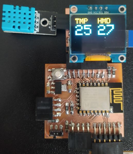
Now that I had working display, I could display the DHT measurements on it. While doing it I had only one real problem when I misplaced the display.display() that updates the display.
#include <Wire.h>
#include <Adafruit_GFX.h>
#include <Adafruit_SSD1306.h>
#include <DHT.h>

#define SCREEN_WIDTH 128 // OLED display width, in pixels
#define SCREEN_HEIGHT 64 // OLED display height, in pixels

#define OLED_RESET     -1 // Reset pin # (or -1 if sharing Arduino reset pin)
#define SCREEN_ADDRESS 0x3C // Silkscreen claims that the address is 0x78 or 0x7A
							// depending of the resistor placement
							// but I2C scan showed that the real address was 0x3C

#define I2C_SDA 2
#define I2C_SCL 14
#define DHTPIN 13
#define DHTTYPE DHT11

TwoWire I2Cssd = TwoWire();
DHT dht(DHTPIN, DHTTYPE);
Adafruit_SSD1306 display(SCREEN_WIDTH, SCREEN_HEIGHT, &I2Cssd, OLED_RESET);

void setup() {
	I2Cssd.begin(2, 14);

	if(!display.begin(SSD1306_SWITCHCAPVCC, SCREEN_ADDRESS)) {
		Serial.println(F("SSD1306 allocation failed"));
		for(;;);
	}
	dht.begin();
	delay(2000);
}

void loop() {
	display.clearDisplay();

	display.setTextSize(2);
	display.setTextColor(WHITE);

	display.setCursor(0, 0);
	display.println("TMP");

	display.setCursor(63, 0);
	display.println("HMD");


	display.setTextSize(4);
	display.setCursor(0, 16);
	display.println(dht.readTemperature(), 0);
	display.setCursor(63, 16);
	display.println(dht.readHumidity(), 0);

	display.display();
	delay(1000);
}
With Adafruit's display driver I could easily change the font size.
Arduino version of the temperature meter
I know that you could use NodeMCU's Lua to program the ESP8266 but I don't think that I have seen many people using that.
You could also just use the AT-commands with the espressif firmware. I know almost nothing about that but I think that it is more targeted to applications where you use ESP8266 just as a WiFi module and something else does the heavy lifting.
Before doing the group work in group I already tested ATtiny412 and ESP8266 at home. ESP8266 performance was terrible compared to the ATtiny412. It was almost ten times slower when it should have been faster. I doubted my measurement setup and made a version that would print the time it took to oscillate 1000 times.
// ESP8266
const int in  = D1; // nodeMCU
const int out = D2; // nodeMCU

unsigned long t;

void setup() {
	pinMode(in, INPUT);
	pinMode(out, OUTPUT);

	digitalWrite(out, HIGH);
	delay(100);

	t = micros();
	for (int i = 0; i <= 1000; i++){
	digitalWrite(out, !digitalRead(in));
	}
	t = micros() - t;

	delay(100);
	Serial.begin(115200);
	Serial.println(); // just to start a new line
	Serial.println(t);
}

void loop() {
}
These results weren't in the line with the results I got previously and guided me to google slow void loop() on ESP8266. I found an forum post that the ESP8266 handles WiFi stuff at the each iteration of void loop(). This is why in the group work we tested most of the devices with two versions of the code. One with just the void loop():
// ESP8266
const int in  = D1; // nodeMCU
const int out = D2; // nodeMCU


/*
// ATtiny412
const int in  = 2;
const int out = 3;
*/

/*
// STM32
const int in  = 7;
const int out = 8;
*/

void setup() {
	pinMode(in, INPUT);
	pinMode(out, OUTPUT);

	digitalWrite(out, HIGH);
}

void loop() {
	digitalWrite(out, !digitalRead(in));
	}
}
And second time with the while(1) loop:
void loop() {
	while (1){
		digitalWrite(out, !digitalRead(in));
	}

}
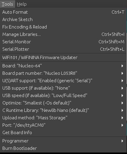
For the different boards we just installed the matching cores to the Arduino IDE. I have already went through that setup before so I won't spam the settings for all of the boards but here is the Nucleo-64 boards settings.
Nucleo-64 settings in Arduino
For the mbed online compiler I had to do couple of steps. First I registered an account to there. Then I plugged The Nucleo-64 board to my computer and it showed as a mass storage device. I opened that folder and clicked the mbed.htm file. That way I imported correct settings for the compiler. Then I opened the blink example and quickly modified to fit our needs. I didn't bother to change the comments or anything because I was in a bit of a hurry.
/* mbed Microcontroller Library
* Copyright (c) 2019 ARM Limited
* SPDX-License-Identifier: Apache-2.0
*/

#include "mbed.h"
#include "platform/mbed_thread.h"


// Blinking rate in milliseconds
#define BLINKING_RATE_MS                                                    500


int main()
{
	// Initialise the digital pin LED1 as an output
	DigitalOut out(D7);
	DigitalIn in(D8);

	while (true) {
		out = !in;
	}
}
Then I just hit the compile button and the browser downloaded the binary file. I moved the binary file to the Nucleo-64 mass storage and it programmed itself.
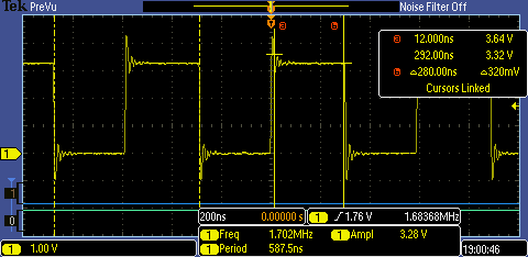
We used the Tektronix MSO 2002B mixed signal oscilloscope to check the frequencies of the ring oscillators we tested. We saved the screenshots from the tests we made so if some one wanted they could compare the signals high and low times later but for mainly we used the oscillating frequency as a way to compare the boards. Sadly I either deleted or forgot to take the screenshots of the Nucleo-64 and Arduino combo. That's way they are approximates from my memory.
Example of the recorded results. This was ESP32 with while(1) loop
When we were doing the group work it felt like we were comparing more the cores/compilers rather than the real hardware performance. The ESP32 was fastest it has the highest CPU clock frequency and dual cores. The surprising part was how terrible the Nucleo-64 and Arduino combo were. It would be interesting to know why.
After I got the MQTT passthrough working I made a function out of the useful stuff from the Hammond Pearces code. I tweaked it a bit so it would work on micropython.
def getData(uart, channel, length):
I modified the MQTT callback function so every time a there would be a message in topic {device}/get1 the above function would excecute.
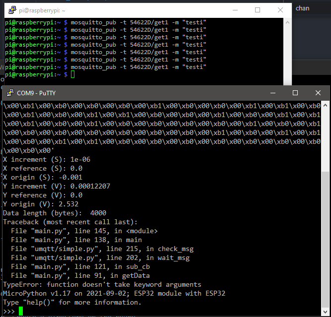
Error about keyword arguments
It was this line:
After reading the docs I learnt that all the arguments were positional. I was slightly worried that the arguments didn't list signed/unsigned argument but ignored my feelings when I didn't get any errors after removing the keywords.
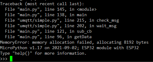
Error about memory
After fixing the the keywords I got a memory allocation error. This pointed to the for loop that converts the received data to actual voltages. Initially I wanted to send the converted data via MQTT because this would allow a easier handling of that in the future, for example if I would store the data in a database. I thought that maybe I could just send the raw data to PC via MQTT and do the conversion on the PC. So I just commented both of the for loops related to conversions.
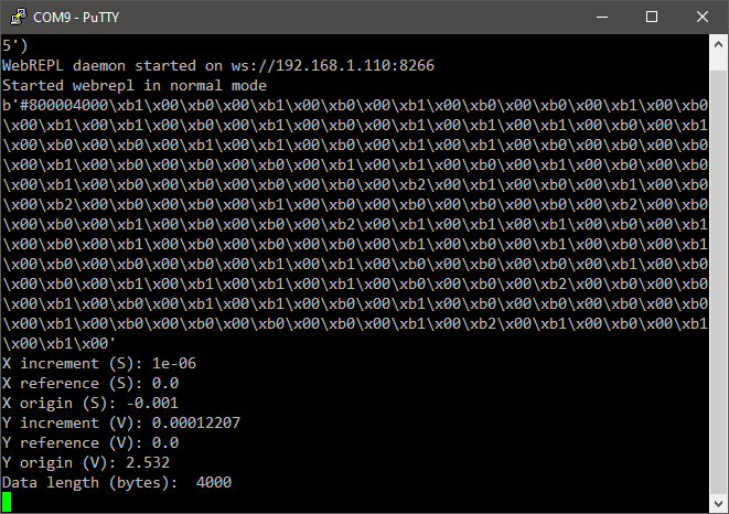
No errors but still problems
Now I didn't get any errors but the b'#800004000\xb1... looked suspiciously short for 4000 bytes and it didn't even end with an \n. I realized that I had some troubles getting all the data from the oscilloscope. I also knew that I got the shorter messages correct (X and Y values in the image above) and when I requested *IDN?\n I got the correct response. I started testing just random settings in the data request, changing the format from word to byte to ASCII but none of them was fully working. While reading micropython UART docs I noticed it had parameter rxbuf and thought that maybe buffer overflow would cause my problems. I tried to set the rxbuf but that didn't help.
Finally I tried tried one of the easiest things that I hadn't yet tried for some wierd reason: Changing the data point amount from maximum/2000 to 100 and this worked! I think the root of this problem is that micropython doesn't seem to have XON/XOFF flow control and without it the RX buffer overflows. I maybe could have implemented the XON/XOFF flow control or DTR flow control myself but I was already behind my schedule so I just moved on. Fewer points also got rid of the memory error that I mentioned above.
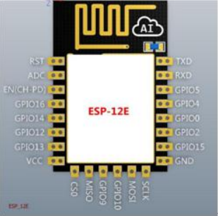 I have read the ESP-12E WiFi modules datasheet almost completely since it's only 18 pages. It had a very Chinese feel to it, for example the picture in the right is straight and uncompressed from the datasheet. I have used this to design my board in the input and output weeks. I read the pin configurations for the UART or Flash Boot modes, or as someone might say programming and running modes, from there.

 I wanted to try MicroPython on this course since I wanted to try MQTT in the networking week and I have read that MicroPython would be a good way to implement it. I also just wanted to try something different than Arduino's C/C++ like language that I have used multiple times in the past. Raspberry Pi Pico came out this year and it has support for MicroPython. I don't have any plans to own one but when someone as big as Raspberry Pi does something, I want to know more about it. I think that's enough of me defending my choice of using a high-level language even though my main interests are in the hardware.