Week 3 assignment
I decided that I wouldn't model my final project idea because to model it in a useful way I would have to spent most of the time available for me in the map editor and not in the programs that are relevant for this weeks assignment.
Inkscape
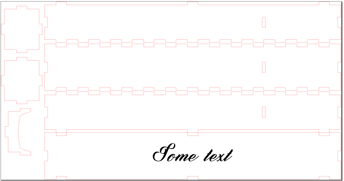
I used an older version of Inkscape (I think it was 0.92) and I had an older extension called tabbed box maker. I don't have a link for the one I was using but it seems like there are two extensions under active development. They are TabbedBoxMaker and inkscape-LasercutBox. I haven't used those.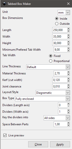 I wanted to make a laser cut box for carving knife. In Inkscape I used the tabbed box maker extension in the laser tools sub-menu. Settings are pretty self-explanatory. I got the cardboard thickness and kerf from a previous years students work. Since I didn't want to go Fab Lab and measure the kerf and the thickness of the material myself, I thought that for this excercise it would be close enough. Also we had the actual kerf measuring assignment in the following week.
You can see my settings on the right.
I wanted to make a laser cut box for carving knife. In Inkscape I used the tabbed box maker extension in the laser tools sub-menu. Settings are pretty self-explanatory. I got the cardboard thickness and kerf from a previous years students work. Since I didn't want to go Fab Lab and measure the kerf and the thickness of the material myself, I thought that for this excercise it would be close enough. Also we had the actual kerf measuring assignment in the following week.
You can see my settings on the right.
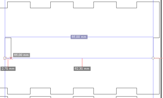
I added a guideline just by pulling from the left and snapped it to the inside corner of the box. By double clicking it I made a note of its X-position. I added another guideline and made its position to be 65 mm less than the first guideline position. Now I could move the divider holes to that position. You can see this below.
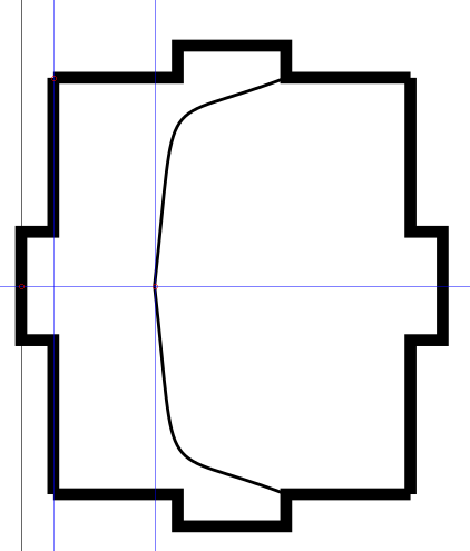 I wanted to use the divider to support the knife from the sheath end. I added more guidelines. For the placement of guidelines, I used the already mentioned method of just adding
wanted distance to the other and I also used snapping to midpoints. I used bezier curve tool to draw one side of the support and cloned it to other side. Then I used the "edit paths by nodes"
to delete the segment between two nodes using this button.
I wanted to use the divider to support the knife from the sheath end. I added more guidelines. For the placement of guidelines, I used the already mentioned method of just adding
wanted distance to the other and I also used snapping to midpoints. I used bezier curve tool to draw one side of the support and cloned it to other side. Then I used the "edit paths by nodes"
to delete the segment between two nodes using this button. I didn't want the top of the box to have so many tabs, so I edited those tabs using node tool. I broke the path in two points, but the path was still "combined". I selected the combined path and used ctrl+shift+K to break that connection with the other paths. Then I could select only the parts that I wanted to delete. Then I just selected both nodes that I want to connect and used the node tool to make a new segment between two nodes.
I wanted to add some text to the lid of the box. I used the text tool for that. I aligned the text to the center of my first selection, which was my lid, in both axis but ended up bringing it down a bit. You can use ctrl when you move objects to only move them in one axis. I also moved the parts for a bit tighter package.
For laser cutting I changed the stroke width to 0.01 mm (I think the correct width is 0.02 mm or less) and changed the stroke color to red. Changing the color isn't necessary but I like to do it so I can visually check that I don't have stroke on in any part of the design that I don't want to cut. For example, in this design I could see that the text didn't have the stroke on. Picture is taken before the stroke width change so you can still see them. I remembered afterwards that you can change the display mode to outline, from the view menu.
Download box.svg
GIMP
This time I decided to check the updates before I started making this part of the assignment. I had GIMP 2.8 and the current version is 2.10. Usually use gimp to edit photos to format that fits to better for laser engraving. I have previously used it to convert images to black and white pictures, change the color bit depth and used different kinds of filters, for example an newsprint filter.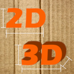 I made a new image in 260x260 resolution and I used transparent background. I added some text and changed color to the same highlight color that I use in my website. I used this tutorial to make a quick 3D effect. So I changed the layer that had the 3D text to image size. I used Long Shadows from the Light and Shadow submenu under the filters. There I played around different settings until I found out what looked pretty good 3D effect. I used pencil tool with the shift key to make the straight lines to mimic the dimensions in modelling tools. I added picture of a cardboard as a background because sometimes best CAD is Cardboard Aided Design.
Download 2d3d.png
Download 2d3d.xcf
GIMP part 2
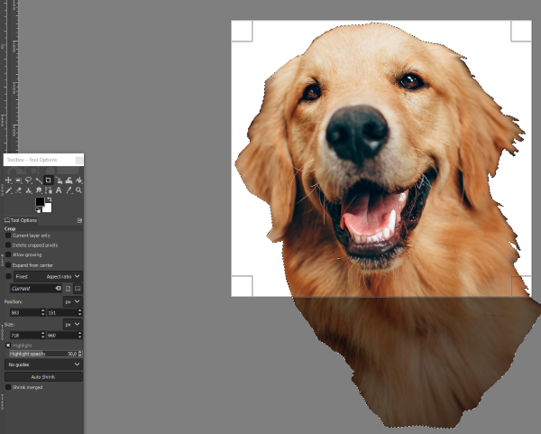
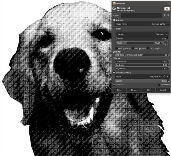
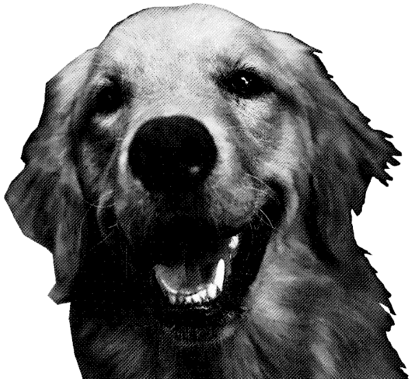
I once engraved two cutting boards made out of wood. For one I used just a regular image and for the other I used image that I edited in GIMP and had used the newsprint filter. The regular image didn't work that well because of the properties of the wood. The wood had hard and soft spots that would interfere with the engraving. The newsprint version worked better because the image is "pixelated".I downloaded image from pexels. I opened the image in GIMP and used the Free Select Tool to select the dogs head. I copied it to new image and used the Crop Tool to crop the image to more reasonable size.
Download dog.png
Download dog.xcf
Fusion 360
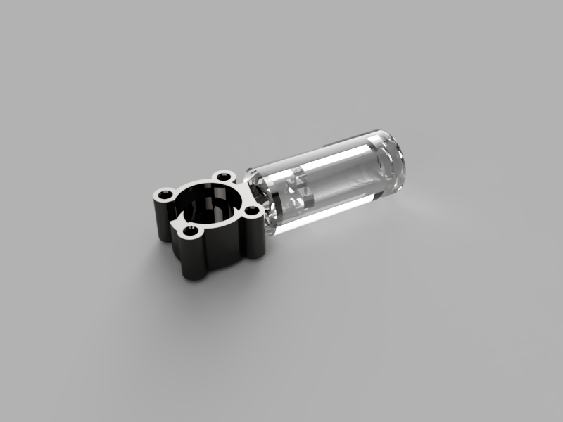
Fusion was saying that my license would expire in 5 days so I went and renewed the student license. I got the renew confirmation to my email but the Fusion 360 program in my computer was still saying that my license will expire in 5 days. I uninstalled Fusion 360 and redownloaded it. After that I got my license working.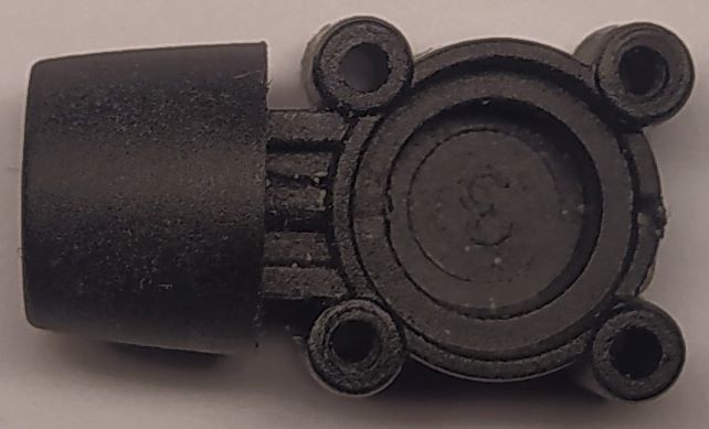 I have a tire pressure gauge that fits to schrader valve but I wanted to use it with presta valves. I though this would
be a great part to model because the finished part would be pretty complicated but it would be made with simple shapes.
In the picture right you can see the original part. The pressure sensor fits the right side so I wanted to copy that part.
Left side of the part I need to redesign to fit a presta valve. If you don't know what schrader valve is, it is the most common air valve in the car tires, that should also give you an idea about the part size.
I have a tire pressure gauge that fits to schrader valve but I wanted to use it with presta valves. I though this would
be a great part to model because the finished part would be pretty complicated but it would be made with simple shapes.
In the picture right you can see the original part. The pressure sensor fits the right side so I wanted to copy that part.
Left side of the part I need to redesign to fit a presta valve. If you don't know what schrader valve is, it is the most common air valve in the car tires, that should also give you an idea about the part size.
In the surface tab in Fusion 360 I added a canvas from the insert menu. I was not going to use the canvas for actual modelling but just for quick visual reference. I scaled the canvas using two points.
 I made a new sketch and created three concentric circles. I moved the canvas to be over the sketch and rescaled the canvas. Now I could see that picture and measured distances don't quite match. That's because of the cameras lens distortion and angle that the picture was taken.
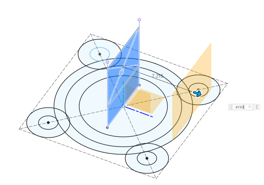
I added four circles around the main part. I gave the first circle the correct dimension in millimeters and for the rest of the circles I just used the first circles dimension. I could do this by just selecting the first circle or typing the name, which fusion 360 automatically gives, to the dimension box. You can see the original sketch on the right.
I made a new sketch and created three concentric circles. I moved the canvas to be over the sketch and rescaled the canvas. Now I could see that picture and measured distances don't quite match. That's because of the cameras lens distortion and angle that the picture was taken.
I added four circles around the main part. I gave the first circle the correct dimension in millimeters and for the rest of the circles I just used the first circles dimension. I could do this by just selecting the first circle or typing the name, which fusion 360 automatically gives, to the dimension box. You can see the original sketch on the right.
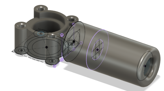
Then I drew a rectangle using center rectangle tool and gave one side a measurement and made the other side equal. Then I moved the four circles inside the square and made them tangential to the sides. Then I constrained the rectangles center point to the center point of the three first circles. I changed the rectangle lines to construction lines. Now I could finish the sketch and start extruding. I picked and extruded the surfaces to their correct surfaces. Then I created a new sketch and projected the area between the two "poles". Then I made a rectangle that was width of that projection and height of the notch that the part needed.
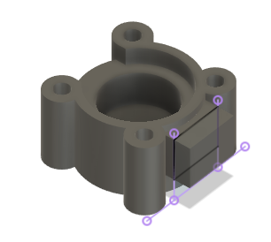 I had some trouble because I drew the next sketch on the wrong plane so I couldn't get the extrusion to work correctly. After I made a new plane and redrew my sketch, I could extrude the rectangle. You can see the offset plane in the picture above. I used extend type "to object" to get it to match with the body. I used just regular "to distance" to get the offset I wanted. You can see the extrusions and the sketch in the correct plane on the right.
I drew yet another sketch and extruded the parts. I added a cross to the inside of the tube so it would press the valve on the presta valve. I added a place for an O-ring at the front.
 Then I added some fillets to the front where you stick the presta valve. I didn't want to add fillets to the O-ring groove because I don't want it to slip in or out of its groove. I plan to 3D print this part and I don't think it will have sharp enough corners to damage the O-ring. I added some small chamfers so the screws would self-tap easier.
I think I need more of everything in 3D-tools. I need to draw more sketches, now I tried to cram too much in to one. I need to create more bodies so they are easier to change. And last but not least I need more time in 3D-tools so I can get a better sense about good order of operations.
I was surprised how long it took to generate the STL file.
Download presta.f3d
Download presta.stl
Rendering
I changed the different bodies to different materials so you could see the internal features in the final rendering.