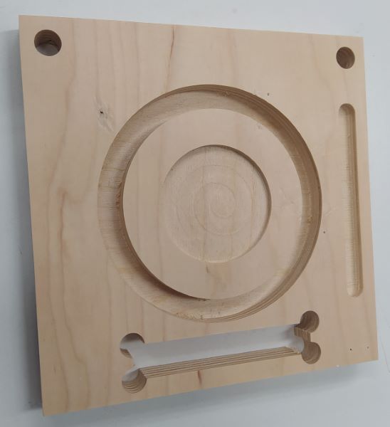
Because of COVID-19, we weren't allowed to do the group work ourselves. Eino Antikainen had milled the test piece and we had just measure it. Only 8 mm flat end mill was used for the milling.
CNC test piece that Eino had made
I made a drwaing out of the test piece in fusion 360. We measured most of the dimensions three times, few of them only twice. Original measurements are downloadable as a PDF. Since I already had the drawing, I thought that it would be a better way to present the results. Measured dimensions can be seen from the images below or from a PDF. Measured dimensions have M as prefix.
Measurements from the top. Numbers with prefix M are the measured results.
The biggest difference between design and milled part was -0.37 mm. That was with the largest circle that was supposed to be 100 mm but was 99.63 mm. Outer measurements were all bit oversized while the inner measurements were bit undersized, except the distance between the two 10 mm holes. This made me think that maybe the milling bit was a bit smaller than 8 mm. It seems like the accuracy was -0.37 mm and +0.14 mm.
Measurements from the side. Numbers with prefix M are the measured results.
The part was modeled with 16 mm thickness but the actual thickness was 14.66 mm. Repeatability on the Z-axis seems to be really good, seems to be on the 0.01 mm range. All the cuts were left a bit too high. I think Eino used the automatic Z-axis zeroing puck to set the Z-height so the puck might be 0.2 mm too high compared to software or some chips stuck under it or something like that that caused the Z-height being too high.
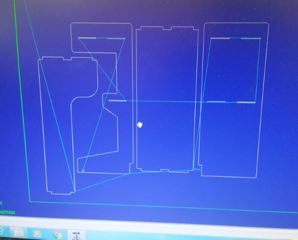
I designed a small table in Fusion 360 that had a notch on the middle plane so my bikes rear fork would fit right next to it. I made slots on top of the table so I could but walls on there so parts wouldn't drop off so easily. I used 3mm pockets so I could put thinner material there. Because I knew that I was going to use a 3mm endmill anyways I designed the dogbones and other reliefs also to be 3mm in diameter.
Example of 3mm dogbones and reliefsInteractive 3D model of CNC table
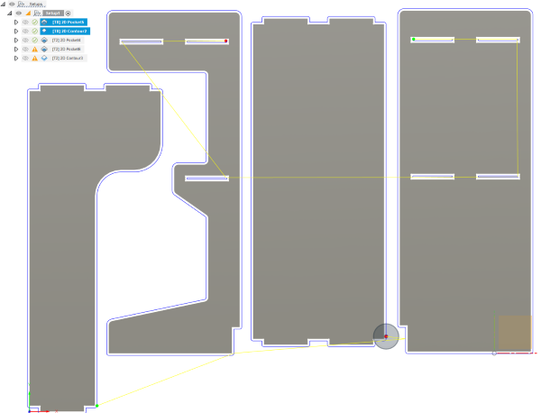
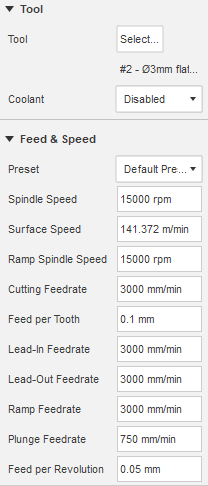
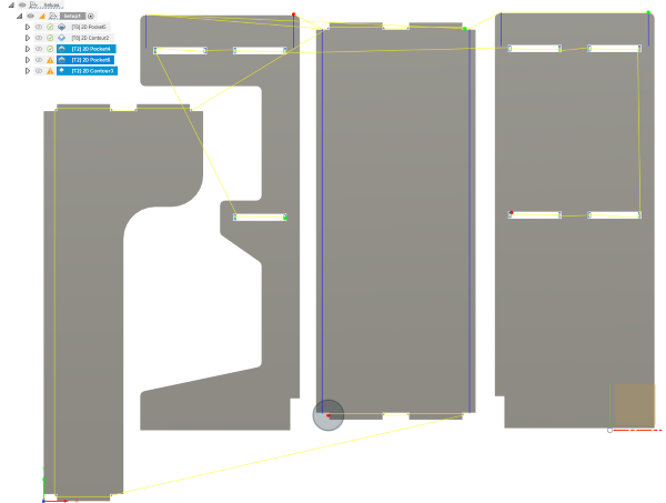
After designing the table I aligned it to XY-plane by just selecting one body at the time and using the align command. After that I just moved everything manually in a way that made some sense. Then I moved to the manuafacture workspace. I set the stock mode to Relative size box and Stock offset to No additional stock. I set the XY origin to bottom left and Z to top of the stock. I used the FABLAB ROUTERI TOOLS library and post processor and used the tools from there. Then I could start making the toolpaths. I thought that I could get away with only one tool change if I used 8mm endmill to remove the bulk of the material first and use the 3mm endmill to do only the reliefs. This meant that I would also need to do the countor milling before changing to 3mm endmill. I verified from Eino that the tabs on the countor routing would be enough to hold the workpiece while milling the reliefs and he thought that they were. I used 2D pocket strategy for the joint slots.
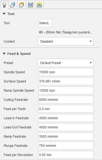
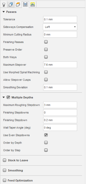
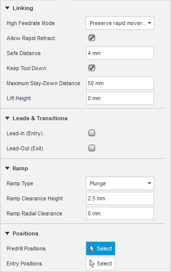
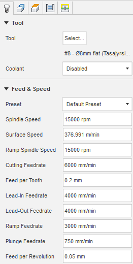
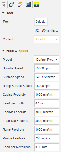
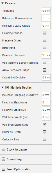
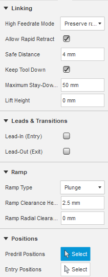
8mm 2D pocket settings. Right click and open image to see them better.
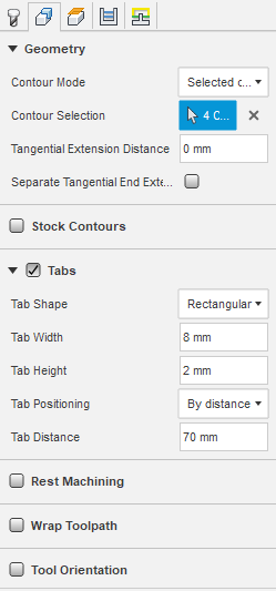
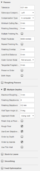
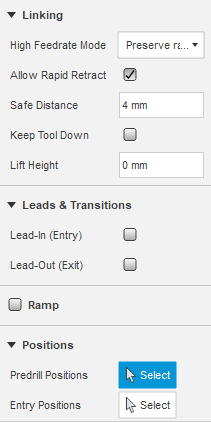
For the outline of the parts I used 2D contour and I used tabs so the parts wouldn't fly out and hit me in the forehead.
8mm 2D contour settings. Right click and open image to see them better.8mm endmill toolpaths
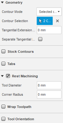
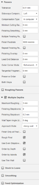
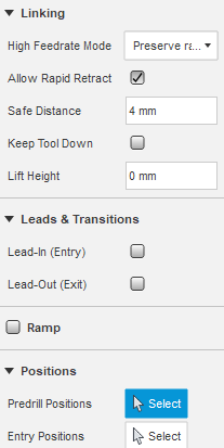
I created three toolpaths for the 3mm tool. One for the top shelf slots, second for the dogbones in the slots and third for the contour. For the two latter ones I used the rest machining option and set the previus tools diameter to 8mm. Because of the rest of the machinining I got a warning saying "Warning: Skipping a pocket since the rest tool has not removed any material.". It seems like the 2D rest machining is a bit dumb and causes this warning. Watching the simulation the toolpaths do exactly what I want so I don't need to care about the warning.
3mm 2D pocket settings for the top shelf slots. Right click and open image to see them better.3mm 2D pocket settings for the outline reliefs. Right click and open image to see them better.3mm endmill toolpaths
I post processed all the 8mm as one NC code and the 3mm toolpaths as a second NC code.
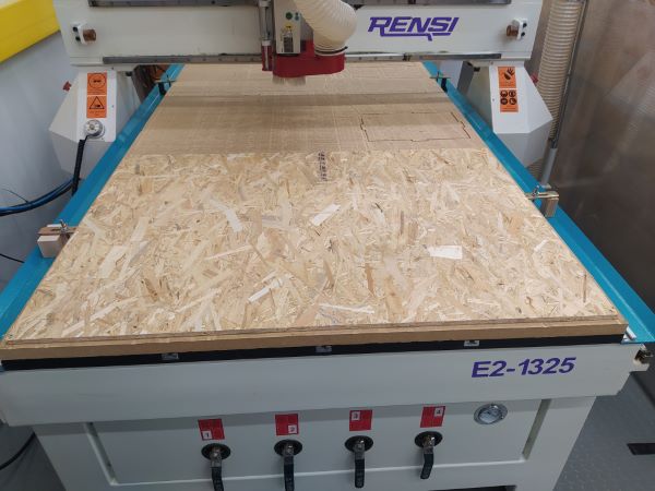
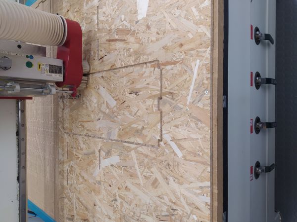
The Router is Rensi E2 1325. First I selected a board where my design would fit. Then I screwed it down on the sacrificial board on the router.
Material screwed to the board
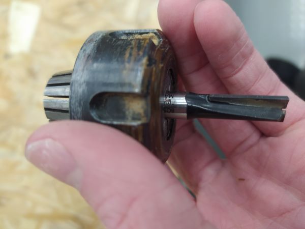
After that I changed the tool and collet. You can clean the collets by banging them to get the chips loose and then blowing them out by compressed air. For the first toolpath I used 8mm wood routing bit.
Collet and router bit
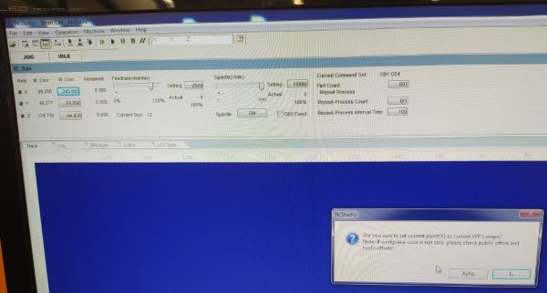
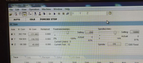
I used a tape measure to measure a good origin point in the XY-plane and jogged the machine there. Then I could set the X and Y Work coordinates in the software.
Setting the X work coordinate to zero
Z-height is set by using the mobile calibrator and holding it on top of the material and under the routing bit while the Z-axis touches it.
Setting the X work coordinate to zero
Then I loaded the NC code for the 8mm toolpaths and simulated it.
8mm toolpaths loaded in the software
I lowered the feedrate and spindle to around 80% during the pockets and then raised it back to 100%.
Lowered feedrate and spindle speedCutting the contour
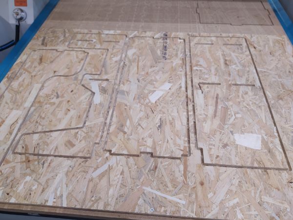
After the 8mm toolpaths were done, I changed the collet and router bit to 3mm and run it's NC code.
8mm toolpaths done
After that I used a stanley knife to cut the tabs and remove the pieces from the stock. I used a belt sander to sand the rest of the tabs away.
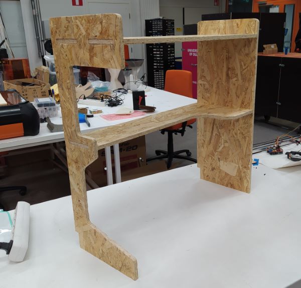
Since I had made the joints exactly 11mm and the OSB was a bit thicker, I had to sand the joints and give them a bit of percussive maintanance to get them fit. Because of the tigth fitting joints the table seems usable.
8mm toolpaths done