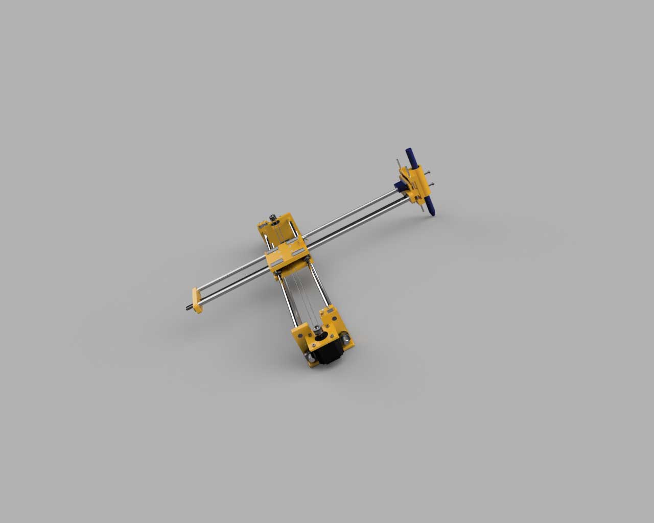
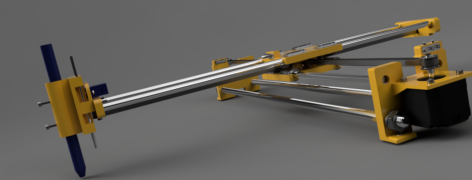
Functioning machine:
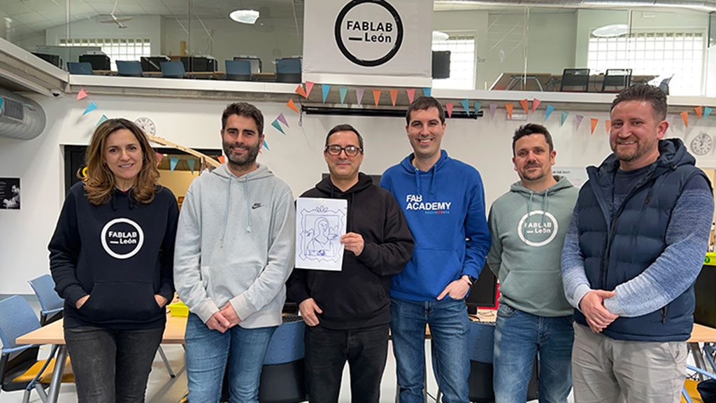
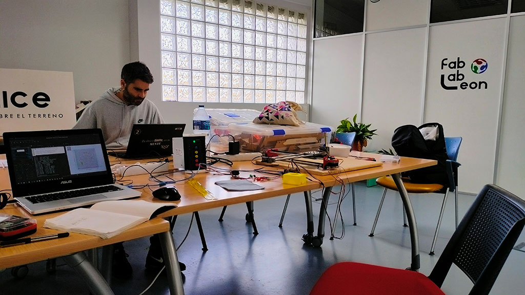
The Team!
We are Pablo Badiola (Deusto Lab) and Pedro Candeias (Fab Lab León). As a team we have managed to work and communicate effectively and independently even living 700 km apart and only meeting once to build the envisioned machine.
The idea
We first started out by exploring the idea of a Clothes folding machine but were soon advised that the machine, as clearly stated in the week's assignment, needs actuation and not just a mechanism+automation and application.
By looking at projects from previous Fab Academy students, one did seem interesting: A drawing machine/bot.
One of Pedro's first final project ideas was a tshirt drawing machine.
He eventually
decided to do something else for the final project so we went ahead to try and build the
best of both worlds, make a drawing machine….that
can in the near future draw on textile.
There are a lot of different drawing machines out there, so we are not really inventing something new, but we do hope to add something to the current designs.
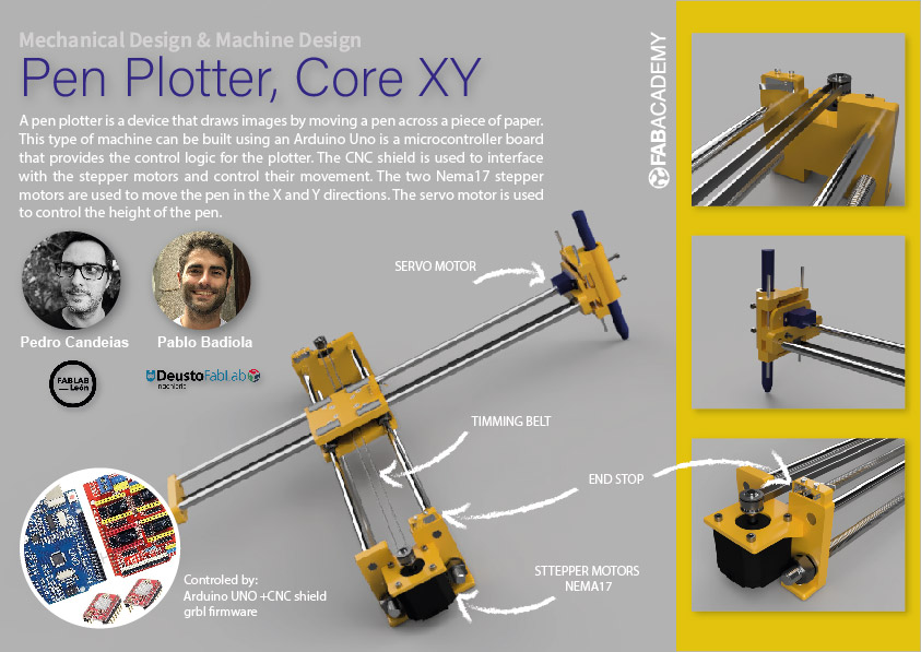
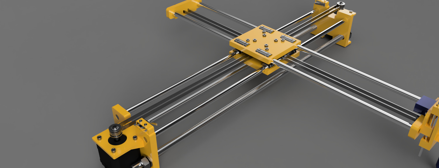
We eventually settle for what is commonly known as CoreXY Pen plotter machine
It's a type of machine that's been done over and over again in Fab Academy and has the advantage of having a lot of instructions online.
Here are some links:
A pen plotter is a device that draws images by moving a pen across a piece of paper. This type of machine can be built using an Arduino Uno, a CNC shield, two Nema17 stepper motors, and a servo motor to push the pen down or pull it up.
The Arduino Uno is a microcontroller board that provides the control logic for the plotter. The CNC shield is used to interface with the stepper motors and control their movement. The two Nema17 stepper motors are used to move the pen in the X and Y directions. The servo motor is used to control the height of the pen. To use the plotter, a design can be uploaded to the Arduino, which will then move the pen in the appropriate directions to create the image on the paper. The servo motor can be used to lift the pen up when it needs to move to a new position, and lower it down when it needs to draw a new line.
For this week's assignment we will only try to build a prototype, but we did try to think of development spirals.
Spirals:
- Build a working prototype:
- Make the machine work from a PC running Universal GCode Sender;
- Make some Gcode test files;
- Draw something;
- Redesign the parts to add more functionality and make the machine
prettier:
- Add an acrylic cover;
- Add End stops;
- Correct parts that need correcting;
- Make a part so that the machine can be in a more vertical position so that you can see the machine working without having to "stand on it".
- Add a way to secure and stretch a shirt;
- Automate the process with a Raspberry Pi and a Camera:
- Write a script in python to automate the process:
- Take a picture;
- Convert picture to line drawing;
- Convert picture to SVG;
- Convert to GCode;
- Send Gcode to machine;
- Start machine automatically;

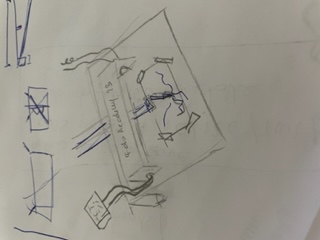
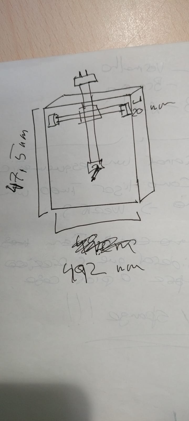
Planning the machine's building
There are a lot of resources online for a machine like this and that help out creating a BOM (bill of materials) of materials.
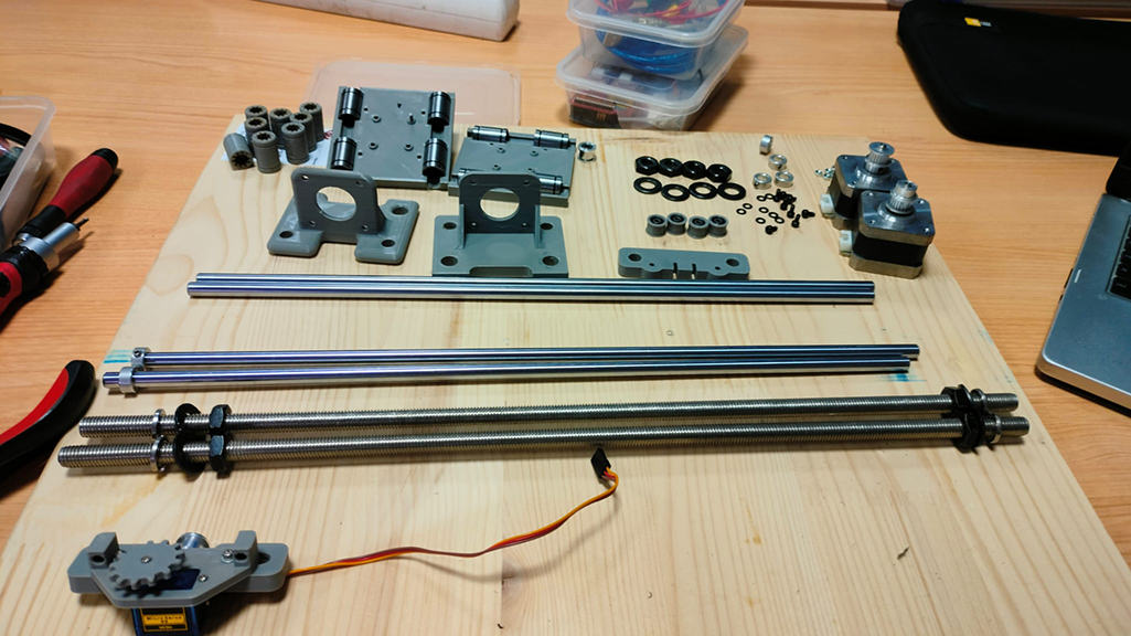
In terms of parts we decided to make a distinction between what we could fabricate and what we would have to source:
Sourced materials
| Quantity | Description | Price |
|---|---|---|
| 1 x | Arduino UNO | -- |
| 1 x | CNC Shield | -- |
| 2 x | A4988 Drivers | -- |
| 2 x | NEMA 17 Stepper Motors (40mm) | -- |
| 2 x | 20-tooth GT2 pulleys | -- |
| 1 x | GT2 Timing Belt (1.4 - 2 meters) | -- |
| 1 x | micro servo SG90 with a long cable | -- |
| 2 x | end stops sensor | -- |
| 1 x | A power supply capable enough to move the motors and servo | -- |
| 1 x | USB cable | -- |
| 4 x | 8mm smooth rods - 400 mm length | -- |
| 2x | M10 threaded rods (400mm); | -- |
| 8x | M10 nuts; | -- |
| 8x | 30 mm M3 screws with nuts | -- |
| 8x | 6mm M3 screws | -- |
| 2x | 15mm M3 screws | -- |
| 4x | 16mm M3 screws with nuts | -- |
| 4x | M3 washers | -- |
| 4x | M10 Washers | -- |
| 4x | M10 Lock Washers | -- |
| 2x | 4mm OD, 100mm tubes | -- |
| 8x | 623EE Deep grove ball bearings; | -- |
| 1x | Small spring, like the ones found in action ballpoint pen.; | -- |
| -- | ||
Fabricated Materials
| Quantity | Description | Price |
|---|---|---|
| 2x | 3D printed: stepper motor mounts; | -- |
| 1x 3D | printed: Pen carriage; | -- |
| 1x | 3D printed: Pen holder; | -- |
| 1x | 3D printed: Y axis carriage; | -- |
| 4x | 623EE Deep grove ball bearings polly; | -- |
| 1x | 3D printed: Y end mount; | -- |
| 1x | 3D printed: Timing belt holder; | -- |
| 8x | 3D printed: LM8UU Bearings; | -- |
| 6x | 3D printed: table fixtures; | -- |
| 1x | Laser cutted: Acrylic cover; | -- |
| 1x | Laser cutted bed riser; | -- |
| 4x | 3D: Clip | -- |
| -- | ||
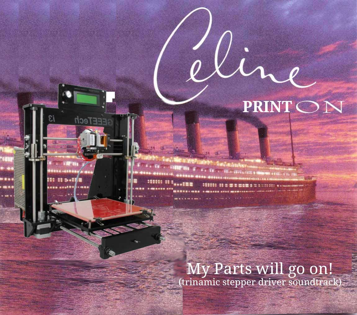
All the parts were sourced from one of Pedro's old 3D printers. The printer's name was Celine PrintOn, in honor of Celine Dion and the loud noise it produced.
Modeling the Machine
After the design of the machine was finished, it was time to model it in Fusion 360 to get the parts to print.
The 3D model of the machine allowed us to correct parts before printing them. It was also useful to create images for the instructions.
Having all the parts, printed or sourced, we can now start building the machine.
How to build it!
Here is first video explaining how to assemble the machine:
Mechanical build
STEP 1:
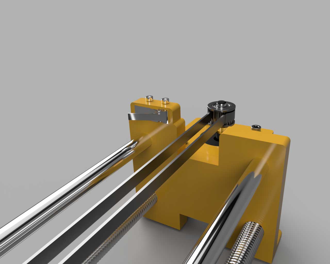
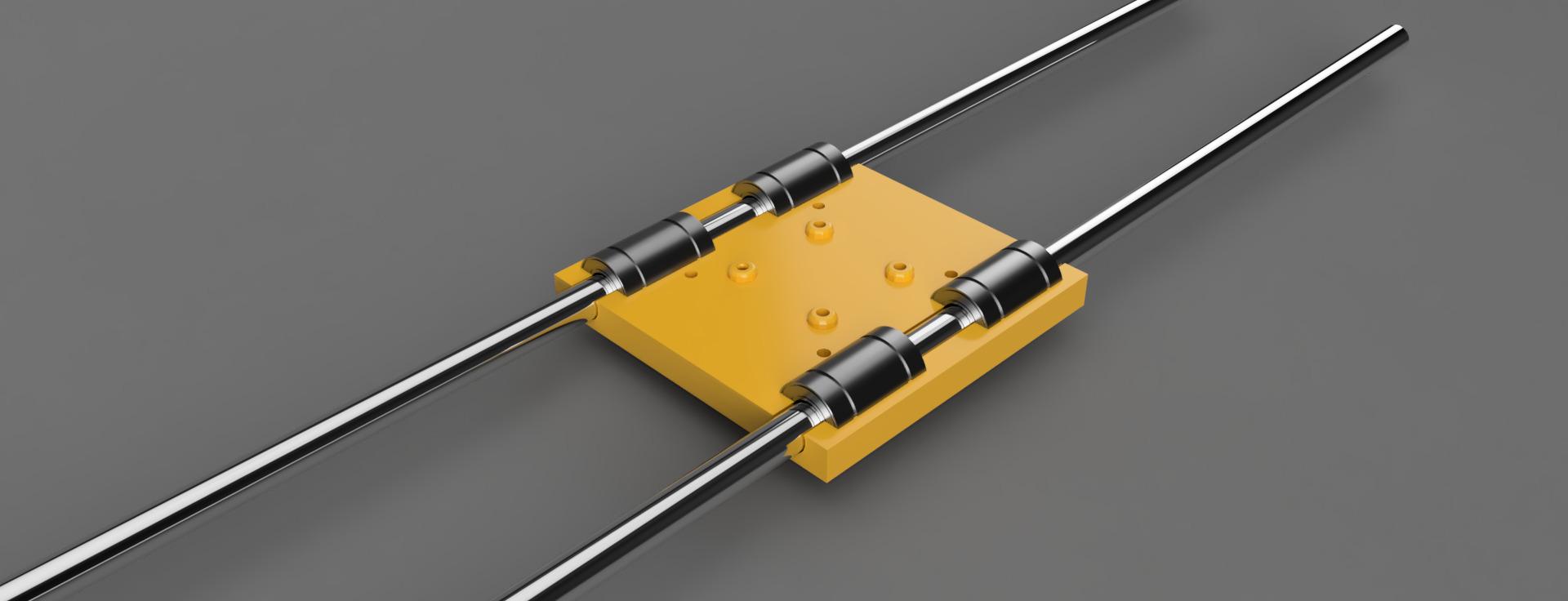
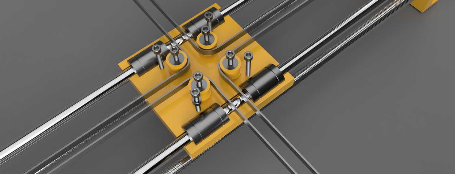
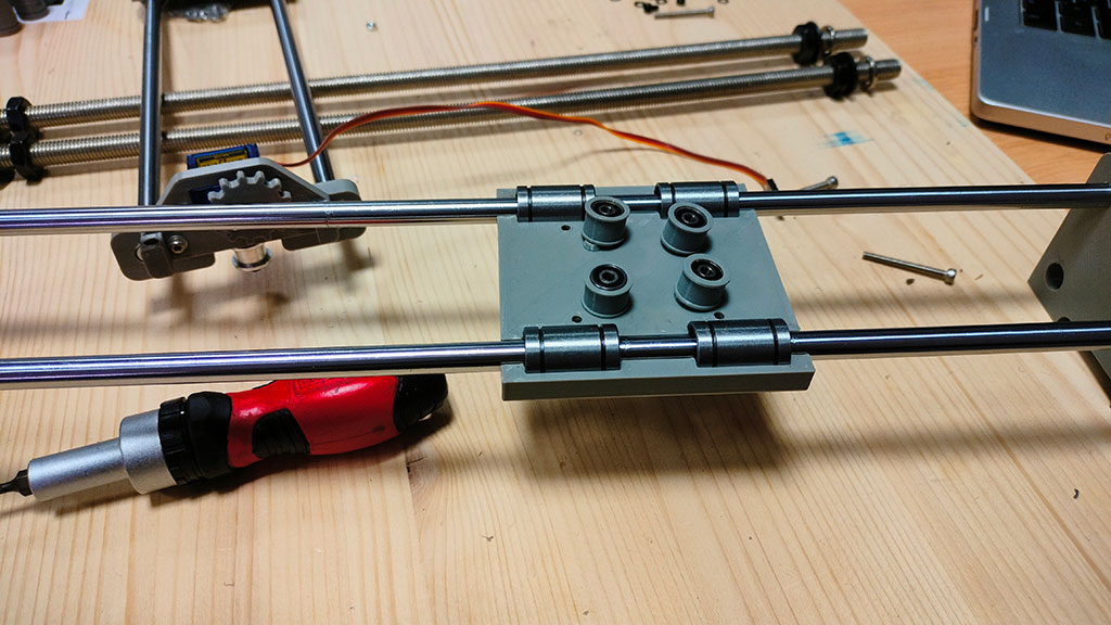
Insert the LM8UU linear bearings in the top square carriage and 4 in the bottom square carriage.
Insert two smooth rods into each of the carriages:
STEP 2:
Insert M3 nuts into the nut-holders in the bottom squared carriage and place it supporting the LM8UU linear bearings.
STEP 3:
Insert Two F623EE bearing into each polly.
Place polly them over the holes in the bottom carriage.
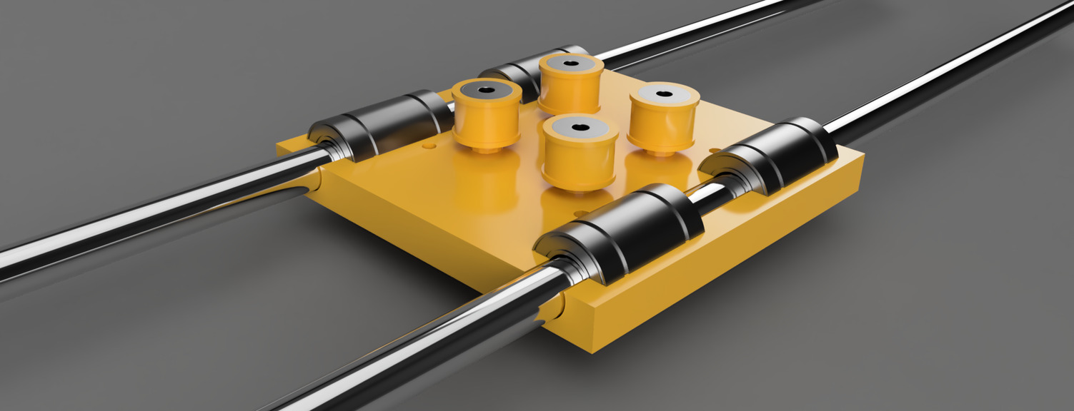
STEP 4:
Place the top carriage over the bottom carriage so the smooth rods on the top form a right angle with the bottom smooth rods.
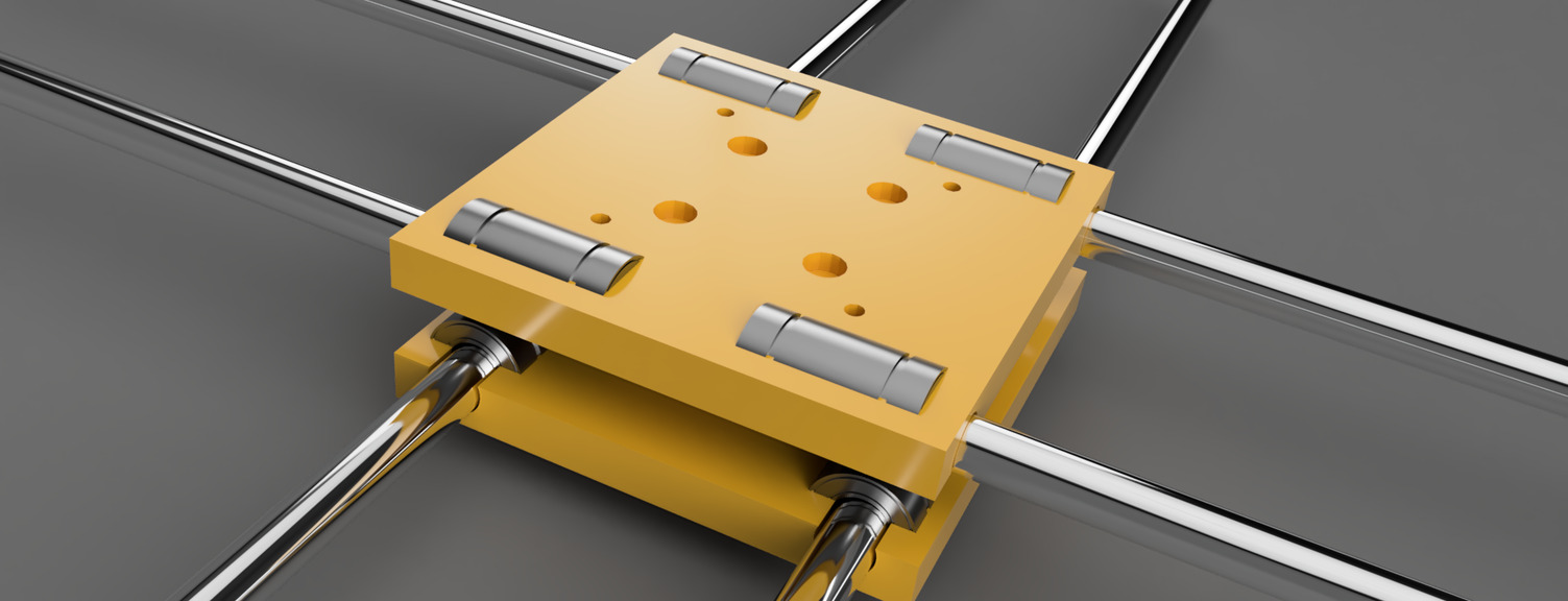
STEP 5:
Insert 30 mm-long screws in the 4 central holes of the top square carriage.
Insert 10 mm-long screws in the 4 outer holes of the top square carriage.
STEP 6:
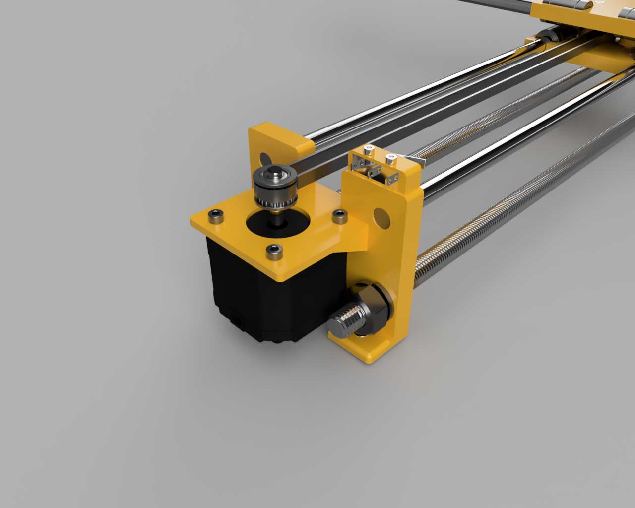
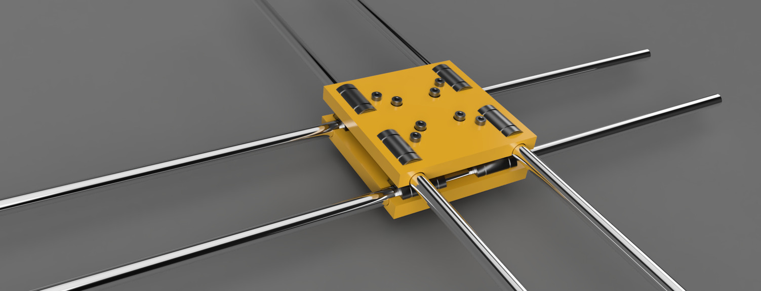
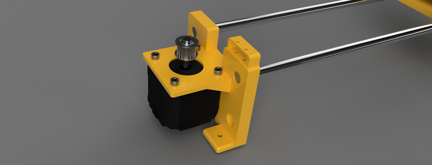
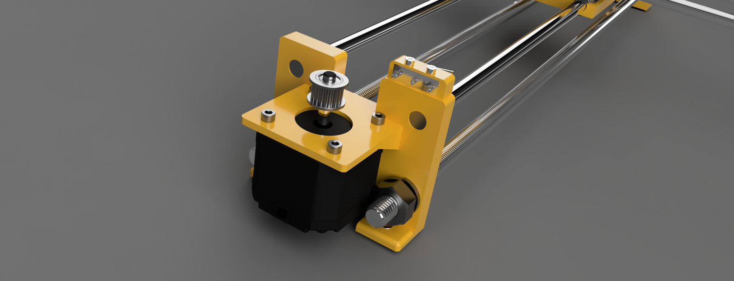
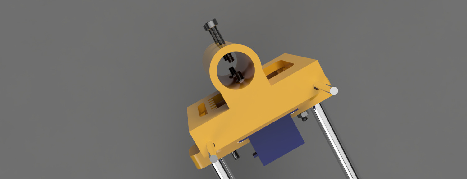
Mount the NEMA 17 stepper motors on the stepper motor mounts and screw the 8mm M3 screws to fix the motor.
Insert the 8mm M3 screws in the stepper motor mounts.
Insert the smooth rods in the stepper motor mounts.
On each stepper motor add a GT2 pulley.
STEP 7:
Insert threaded rods in the stepper motor mounts and screw in the M10 nuts as well as the washers.
Don't make it too tight and try to make it so that each side has the same spacing.
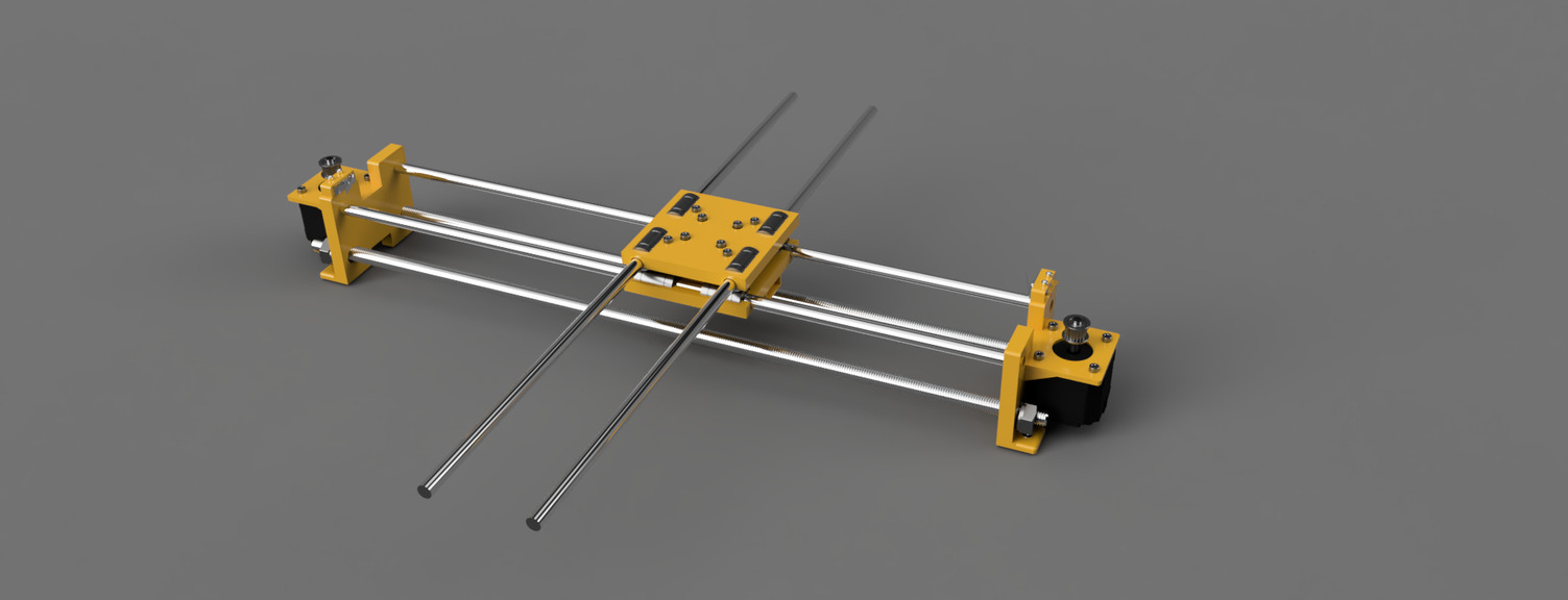
STEP 8:
The machine should look like this at this point:
STEP 9:
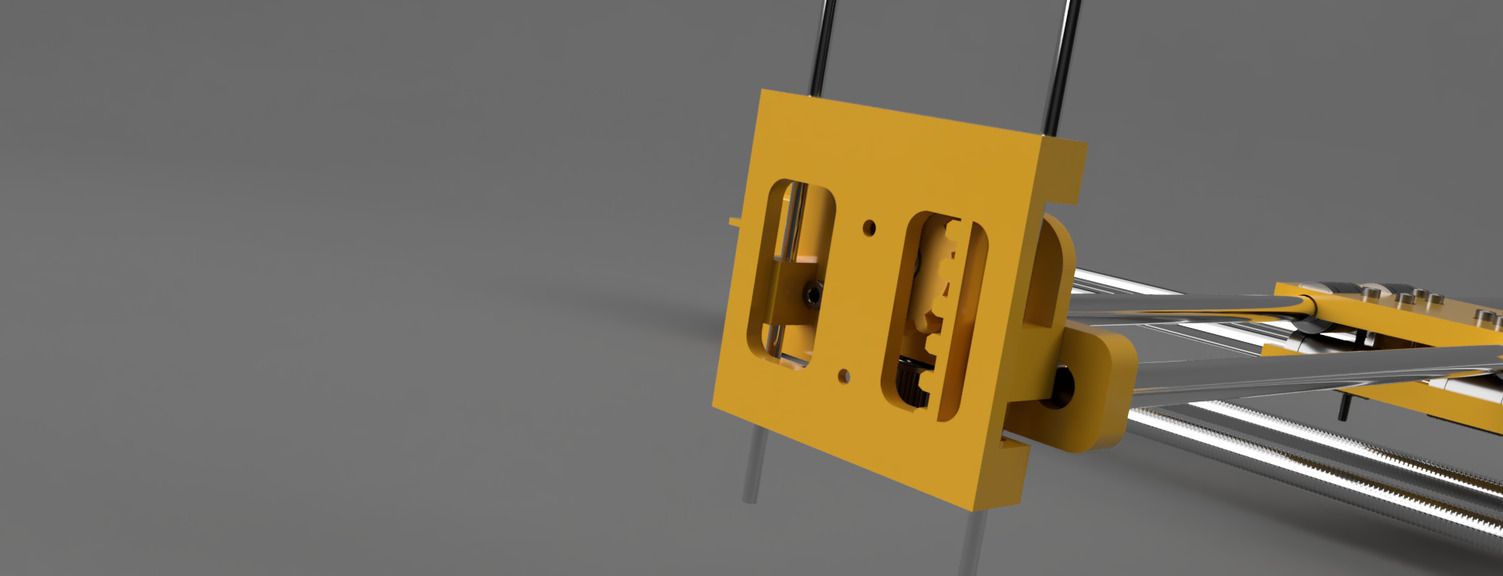
Insert the Y End part into the smooth rods. Some pressure is needed.
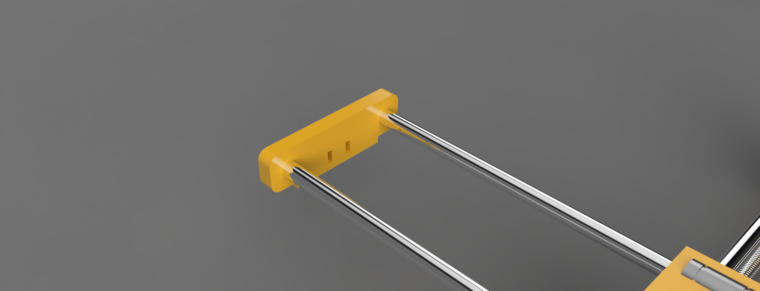
STEP 10:
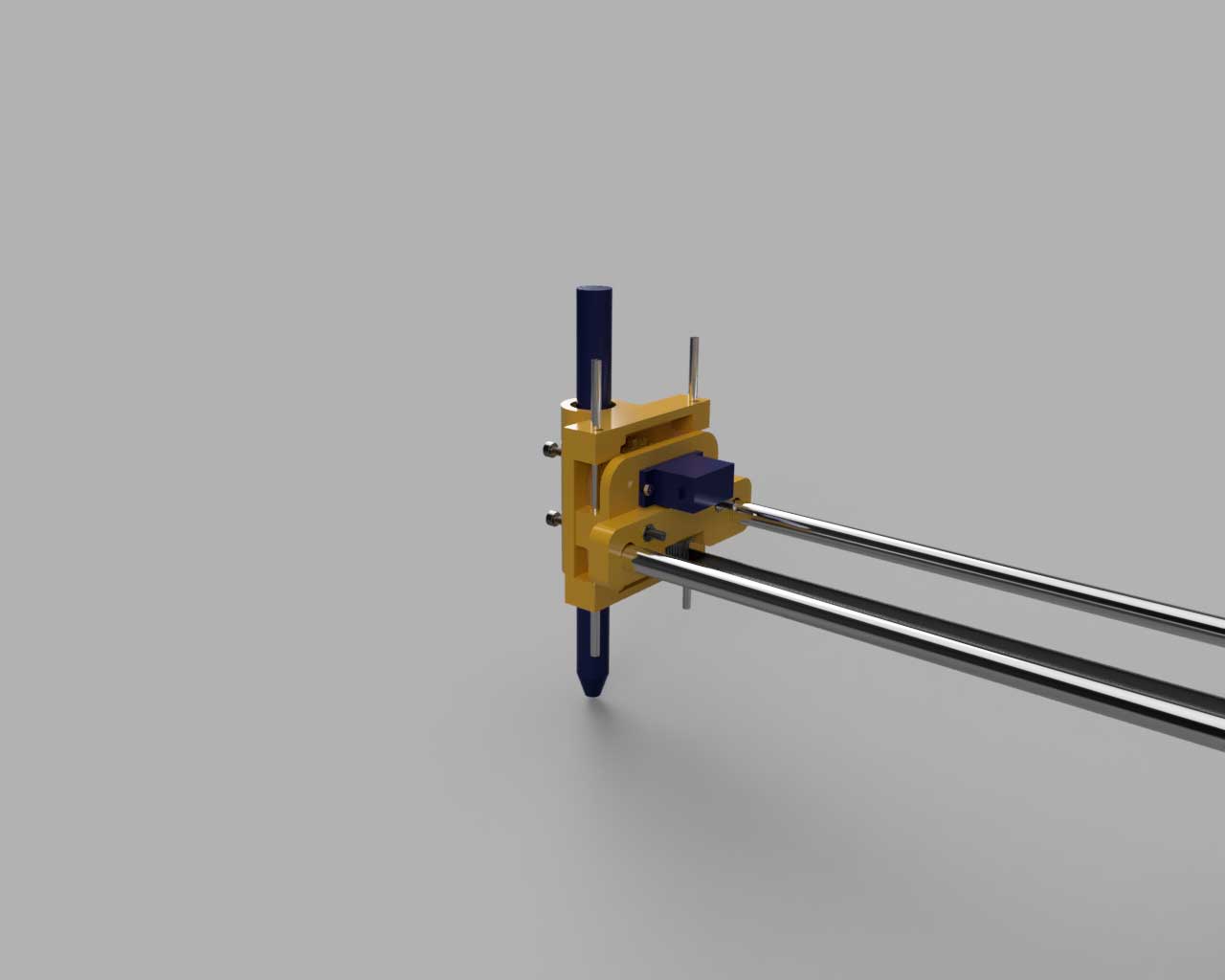
On the other side insert the second Y end that supports the servo motor and pen older.
Use two M3 screws and two nuts to attach the servo support part.

STEP 11:
Attach the servo using the two screws that come with it.
Insert both cylinders from the top but only mid way.
Insert the sprocket wheel and attach it using a screw.
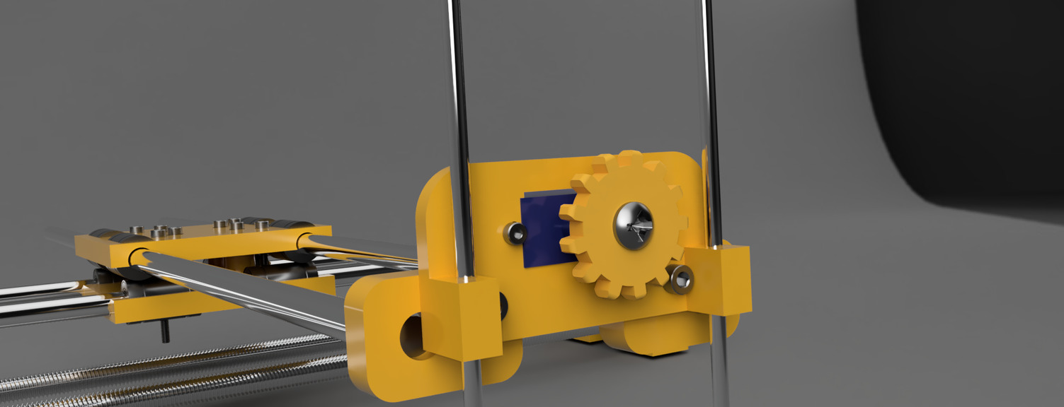
STEP 12:
Fix a polly with an M3 screw to the Y End part that has the servo.
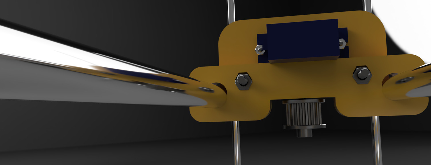
STEP 13:
Insert the actuator part into the two cylinders so that the sprocket wheel turns and lifts or lowers the actuator carriage.
STEP 14:
Attach the pen holder using two M3 screws and nuts to the vertical actuator carriage. Add two more screws and nuts to fix the pen in place.
STEP 15:
Insert the belt. And once pulleys are aligned with the belt tighten the grub screws on one of the Y Ends using a clamp of a screw.
STEP 16:
The machine should look like this:
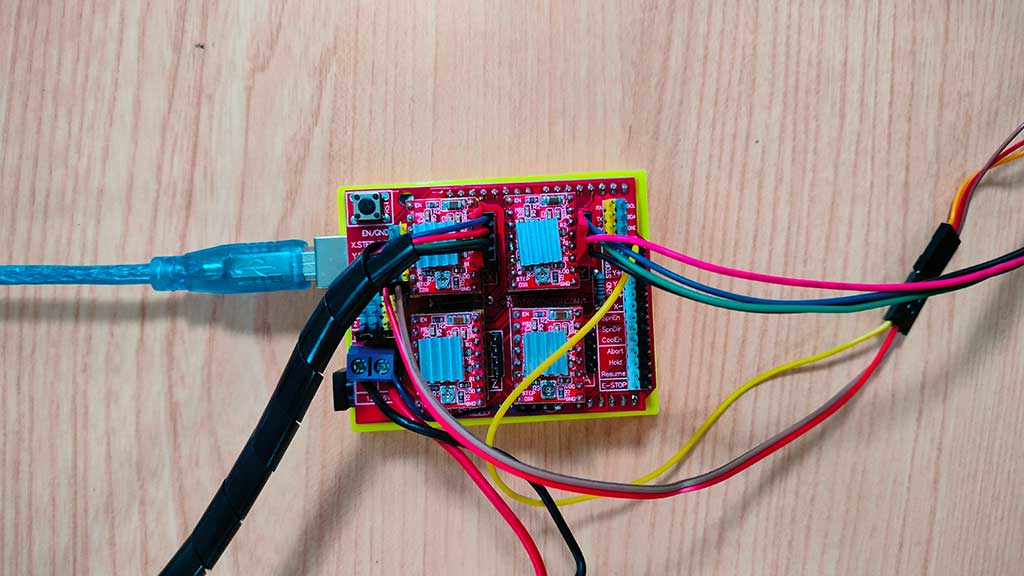
Electronics set up:
- Place the CNCShield board on top of the Arduino board.
- Put three jumpers in the headers near the motor drivers.
- Insert two of the stepper driver boards on top of the CNCShield board.
- Connect the servo and the stepper motors to the CNCShield board.
- Connect the three-wire cable from the servo to the +5V (red), GND (black), and signal (white or brown) pins on Digital pin 11.
- Connect each stepper motor to the X and Y axis four-pin headers on the CNCShield board.
- Connect end stops to the CNCShield board.
- Connect the USB cable to the Arduino board and the computer.
- Connect the power supply to the CNCShield.
The wiring should look like this:
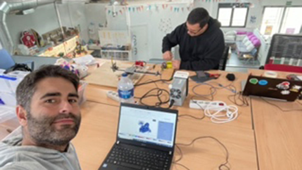
We are almost done!
The instructors patiently wait for us to finish on a Saturday afternoon.
Software:
Before making the machine draw something we must burn into the arduino the GRBL library.
Installing GRBL
GRBL is a "An open source, embedded, high performance g-code-parser and CNC milling controller written in optimized C that will run on a straight Arduino and although it can be seen as outdated, the truth is that it works!
The latest release was downloaded from GitHub (link here) and installed.
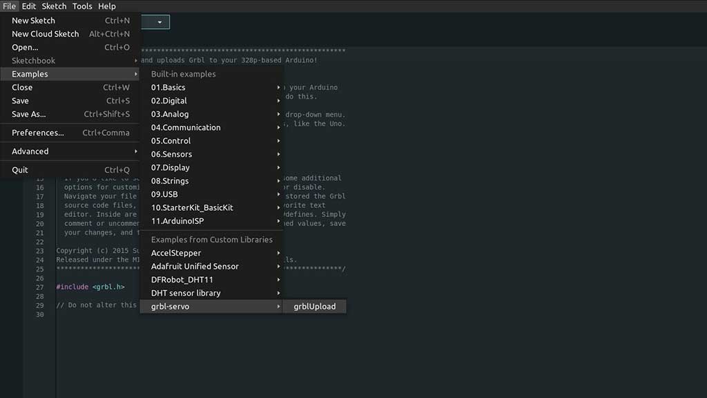
After the installation, in Arduino IDE, we needed to go to the File > Examples menu and select the GRBL Upload example and upload it to the Arduino. GRBL Upload.
Universal Gcode sender
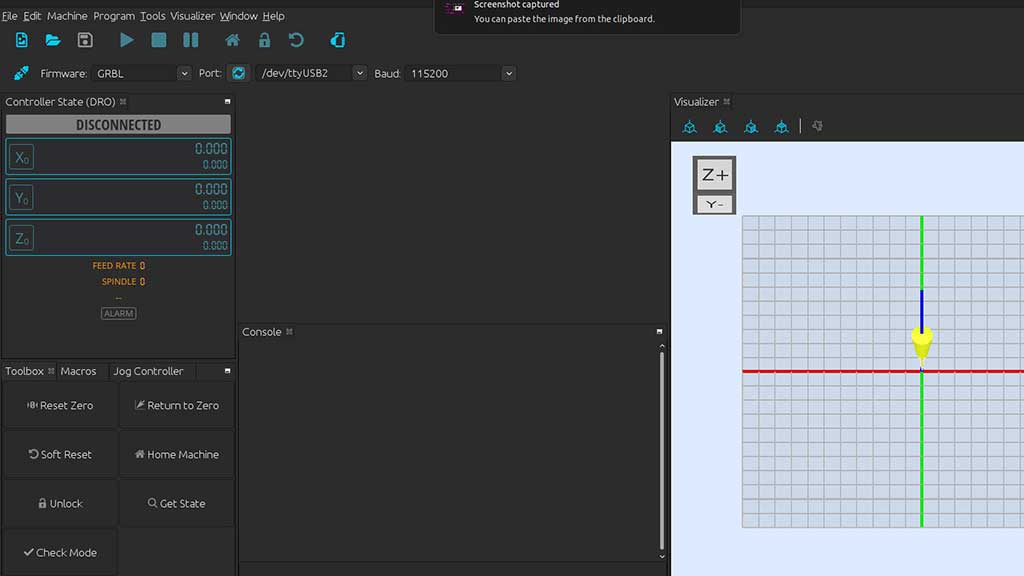
Now we need a way to control the motors and servo. For that we are going to use the Universal Gcode Sender.
A cool thing about UGS is that it runs on pretty much any popular computer OS and works with pretty much any controller. Universal GCode Sender is a freeCNC controller software package. The “Universal" designation means means that it will work with a lot of the firmware options around, such as G2core, TinyG, and GRBL.
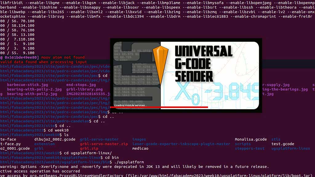
Universal Gcode Sender can also be downloaded from GitHub
After extracting the files, Inside the main folder there will be a bin folder and inside that folder there is a ugsplatform file.
Via command line/terminal, navigate to the bin folder and type ./ugsplatform, that's it.
Now we can access the firmware settings by typing $$ in the text box on the bottom of the interface.
The parameters $100 and $101 define how many steps are required for the
machine to go 1mm.
The Nema17 stepper motors we are using is a 200 steps motor, and the GT2 timing belt is a 2mm pitch,
so I found online that the value for $100 and $101 should be 80.
As we can see from the prompt the values are very different, so we need to adjust them.
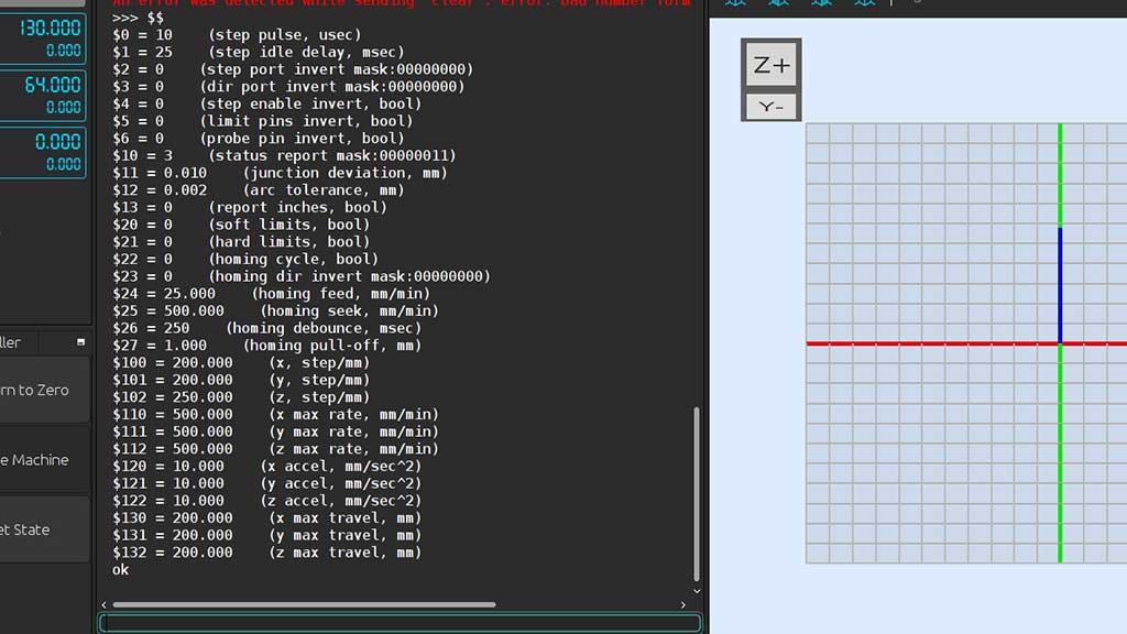
I will later measure the distance the machine travels for 100mm and make the necessary adjustments but for now, 80 will be the value.
To introduce a new value we just need to write in the terminal $100=80 and
$101=80.
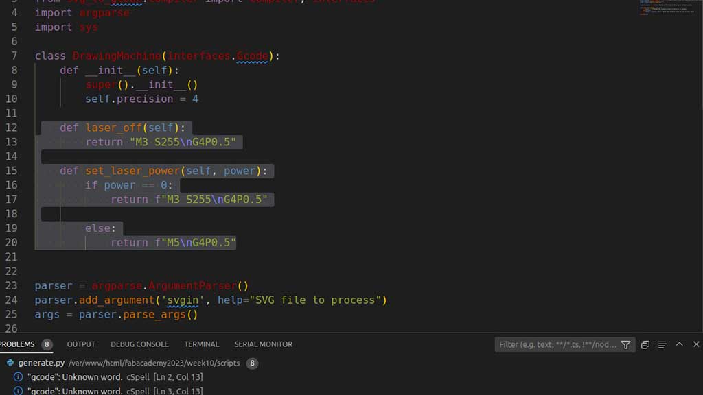
Creating GCode considering the Servo
There are a lot of ways to create Gcode. I can use Inkscape, Prusa Slicer, Tinkercad and.. Python!
The challenge here is that we are using a Servo to push the pen Down or pull UP. Instead of a Laser, we will use a servo and the Gcode must include the M3 S255 to push the pen Down and M5 to pull it up.
After downloading the generator.py file from the downloads sections of this page, just write in the
terminal python3 generate.py name-of-the-svg-file.svg and the script generates a Gcode
file that you can use in Universal
Gcode Sender.
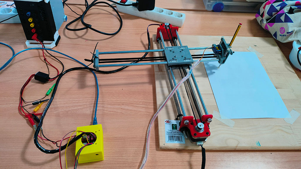
Building and testing:
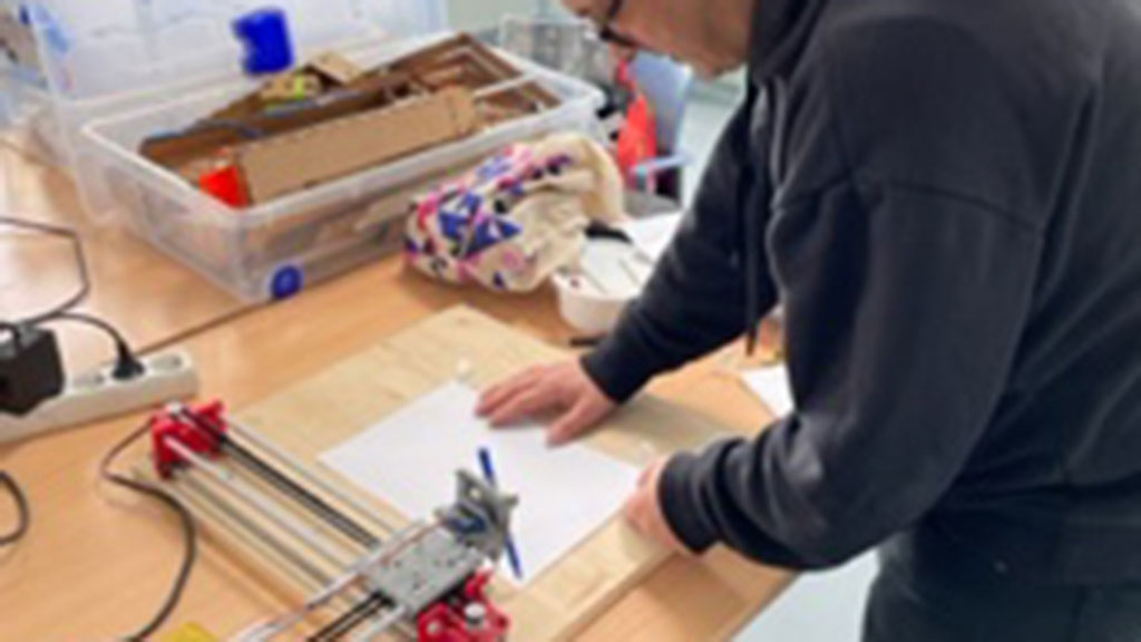
A brief explanation of how the machine works:
Both motors control the X and Y axis at the same time:
- If both motors turn in the same direction, the head moves in the X axis;
- If both motors turn in the opposite direction, the head moves in the Y axis;
- If only one motor turns, the head moves in diagonal;
Principle of Operation
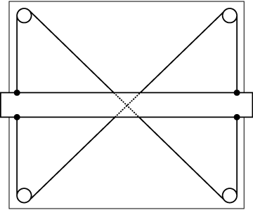
This is a standard drafting table. The horizontal bar is a straight-edge which can be moved up and down by the user. The criss-cross pattern of the cables stabilizes the bar and keeps it horizontal. |
This effect can be seen by following the direction of motion of the two cables which comprise the mechanism. Note that all of the vertical arrows point in the same direction. |
You could imagine attaching a stepper motor to one of the pulleys. Now, the horizontal bar can be moved up and down under computer control. This might be called a single-axis CNC stage. |
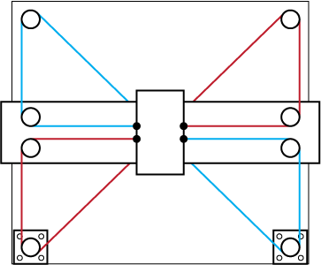
How might we modify this mechanism to convert it into a two-axis CNC stage? The illustrated mechanism above is one solution. Rotating both motors in the same direction results in horizontal motion. Rotating both motors in opposite directions results in vertical motion. |
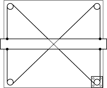
Reference Mechanism
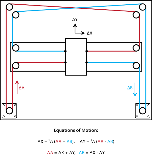
This reference mechanism is functionally identical to the last figure in the prior section. Two additional pulleys have been added to shift the belt cross-over outside of the working envelope.
Going further:
Design and build a cover and a stand for the machine:
Files:
- STL files: Machine version 1
- STL files: Machine version 2
- Complete Machine: Step file
- Complete Machine: Fusion 360 File (External)
- Mandalorian GCode
- Scripts to generate GCode
- Machine cover files
Links:
- Axidraw Pen Plotter Clone
- Multicolor DrawBot/
- CoreXY CNC Plotter
- Dual Task CoreXY DrawBot/
- 3D Printed Arduino CNC Drawing Machine
- Generate GCode from image using Inkscape and Python
- Brachiograph
- fAB SAND PLOTTER
- Sisyphus Sand plotter
- Digital Daguerreotype
- DrawingBotV3
- From JPG to GCode
- CoreXY theory
- Fab Sand Plotter
- Fab Lab Kamakura Core XY Pen Plotter
That's it