10. Input devices
Group Assignment
For this week’s group assignment, we worked remotely, so it was a bit difficult to catch everything going on. We each set up the same ultrasonic sensor with Arduino at our houses, then talked about what they did over zoom. Some of the pictures of my setup appear in the documentation, as well as screenshots I took of Henk sharing his screen.
Henk used a logic analyzer to demonstrate that the sensor sends a pulse of sound, then receives an echo, and measures the time between these to register distance. It was cool to get an input device working so easily, and see how much is going on at the level of the electronics, that even the basic elements we are putting together do a lot.
Inputs
For this week, I wanted to first try using a few of the input devices we got in our quarantine kit with a development board. I tried get the Arduino clone I was using (The Diavolino) working via the FTDI cable Henk made us in the kit.
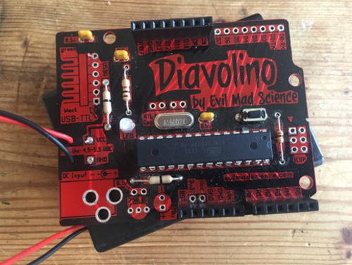
I was able to program Blink on to it, but the connections were too delicate to be able to program it most of the time, or even to supply it power.
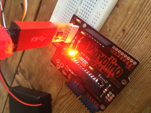
I tried configuring it in several ways on the breadboard, but could not get it to be stable, so will have to wait until I can solder it. Additionally, I thought for some time that the issue might be the “Programmer” selection in the Arduino IDE, as I kept getting the following error:
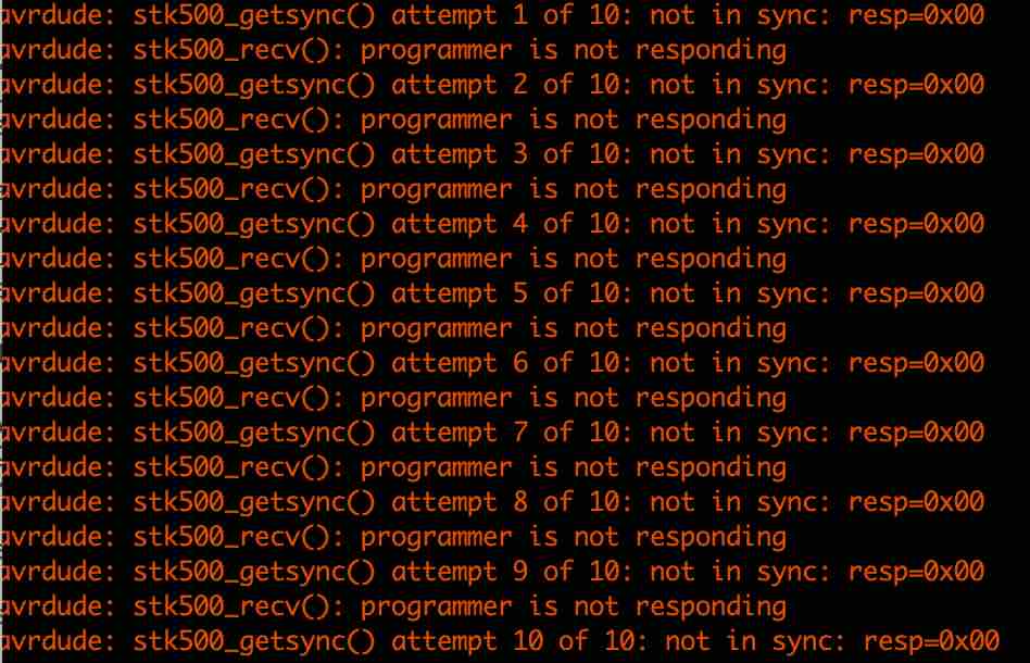
After doing some research, I found that on this board, as on Arduinos, the “Programmer” selection does not matter, as the Arduino has its own bootloader.
So, I decided to continue to use the Node MCU that Harm had given us to experiment with different inputs.
Humidity and Temperature Sensor
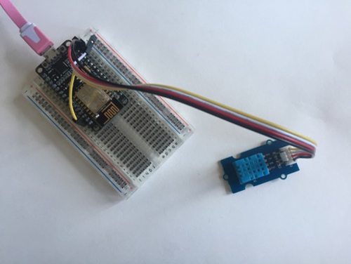
First, I decided to work with the temperature and humidity sensor.
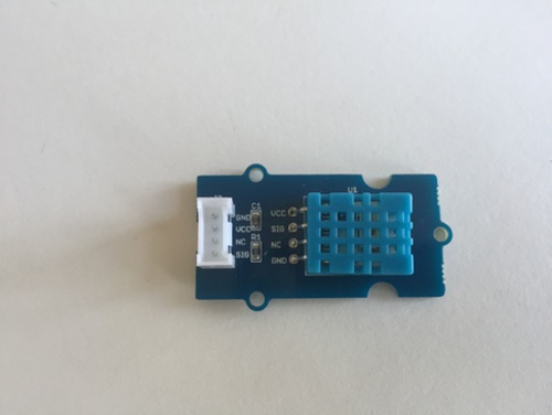
First, I connected VCC and GND to the NodeMCU using a breadboard. Next, I realized I had no clude what to do beyond this, so I looked up the device and how to use it with NodeMCU and found this:
NodeMCU + Humidity Sensor + Arduino IDE
The tutorial was quick and easy. I downloaded the libraries they provided, then ran their code, with the NodeMCU and Sensor connected:
#include "DHT.h"        // including the library of DHT11 temperature and humidity sensor
#define DHTTYPE DHT11   // DHT 11

#define dht_dpin 0
DHT dht(dht_dpin, DHTTYPE);
void setup(void)
{
  dht.begin();
  Serial.begin(9600);
  Serial.println("Humidity and temperature\n\n");
  delay(700);

}
void loop() {
    float h = dht.readHumidity();
    float t = dht.readTemperature();
    Serial.print("Current humidity = ");
    Serial.print(h);
    Serial.print("%  ");
    Serial.print("temperature = ");
    Serial.print(t);
    Serial.println("C  ");
  delay(800);
}
This produced the following readout in the serial monitor:
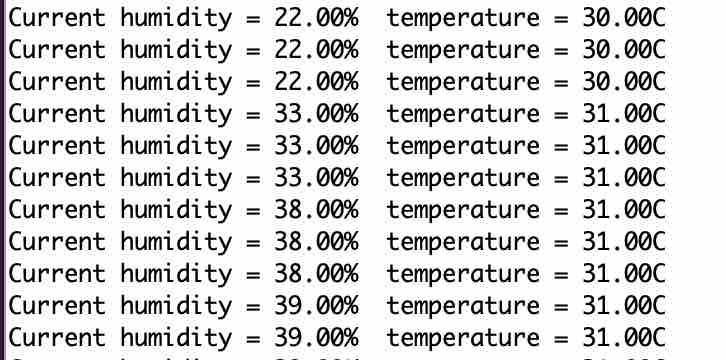
I blew on the sensor and was able to see some adjustments, so it seemed to be working, though humidity fluctuated more than I thought it should have without contact.
Accelerometer
For the accelerometer, I found this tutorial
I did not know if the accelerometer that I had was a clone of the ADXL345, but the connections looked similar, so I thought I would try to use them and the ADXL345 library from sparkfun and the example sketch.
After looking at a few more of the components Harm had given us, I finally found a brand name- Grove. I searched for “Grove accelerometer” and found out it was, in fact, based on the ADXL345.
I looked up the SCL and SDA pins on the nodeMCU, and found they were D1 > SCL, D2 > SDA.
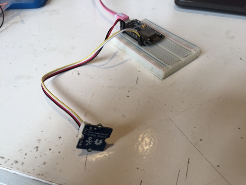
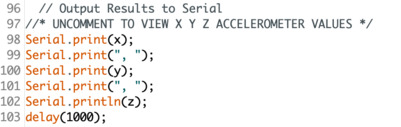
I connected the accelerometer to 3v3, GND, D2 and D1. I wanted to read X, Y, and Z values on the serial monitor. I looked in the sketch, and found the part where I could do this. I had to uncomment this area, otherwise it would only display “Interrupts.”
I ran the serial monitor, and the display went by too fast, so I added a delay(1000).
But it worked. it is cool how easy it is to get components up and running with development boards, and I also liked how easy it was to use the libraries.
Step-Response
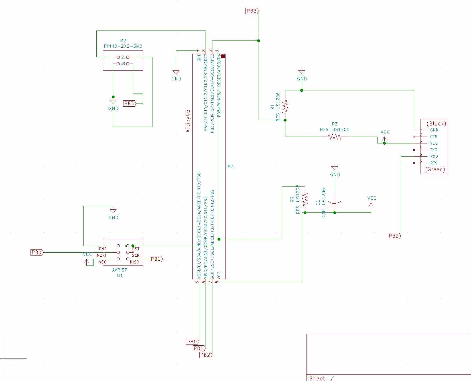
I decided to make Neil’s Transmit-Receive Step response circuit.
I opened up KiCad and began laying the components I saw in the components image.
I first ran into trouble with the tiny45 symbol, as it was very long and made me think it would have the wrong footprint. I spent a lot of time downloading symbol and footprint libraries. As a reminder on how to do this:
Go to Preferences > Manage Symbol/Footprint Libraries> Click the Folder Icon (Add existing library to table)
Symbol libraries will be a .lib file, while footprint libraries will be a .pretty Directory or .mod file.
Sometimes, Manage Footprint Libraries would disappear from my Preferences menu in the schematic editor, but it was always available when I was in the PCB editor. After spending probably an hour looking for a library with the correct Attiny45 and making sure they were all linked to in KiCad, I gained a betetr understanding of the difference between Symbols and Footprints. For some reason, I hadn’t thought to look at the actual footprint for the tiny45 from the fabacademy library, and assumed it would correspond to the long, rectangular symbol. I finally did this after downloading it from elsewhere, only to see it had been right all along. At least I now had a symbol that looked more like it as well! I also downloaded the power symbols, which were missing. Still getting used to the KiCad interface.
As I was away the week of electronics design, I also did not have a good understanding of global labels, so i decided to get an understanding of those this week.
I then connected all of the traces on the board, following closely what Neil had done on his example. Because we do not have access to the lab due to Coronavirus, we are currently sending our designs to Henk to mill then picking them up. I am still new to electronics design, so I did not want to try anything too difficult or get creative and risk not being able to redo my board.
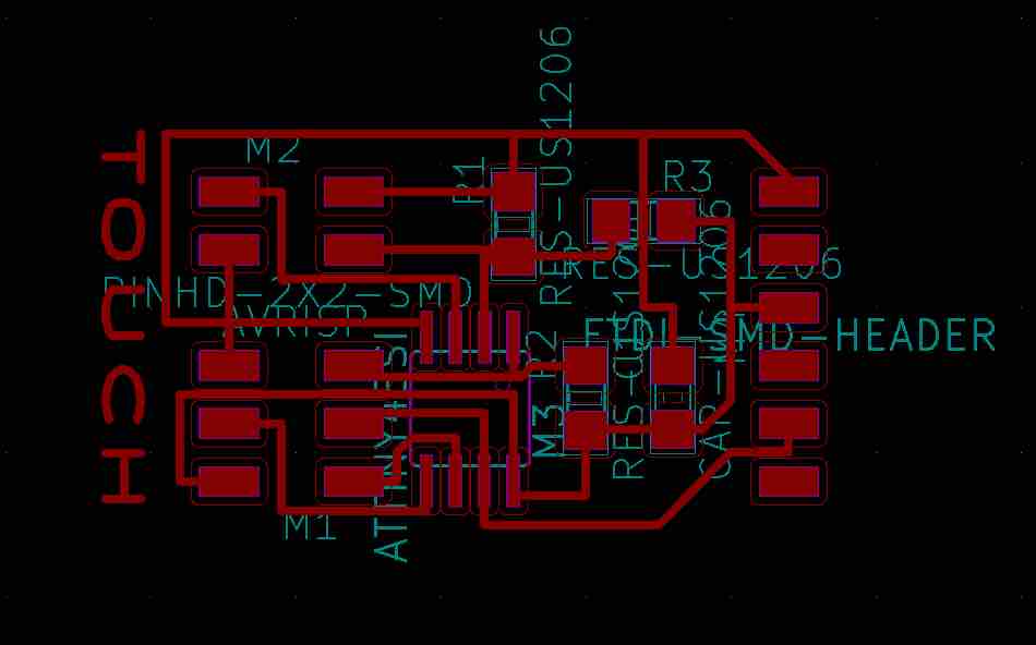
At first, I sent a file with too tight of a border to Henk, and it ended up cutting into the traces.
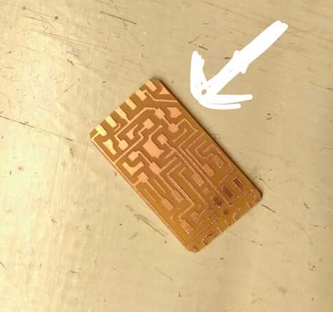
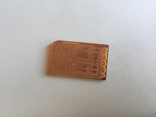
Here is my final board, with wide enough outline:
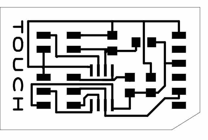
It milled successfully. Thanks Henk!
Because of Corona and lab closures, Henk also gave me a USB powered soldering iron and all the components I would need so that I could stuff the board at my house.
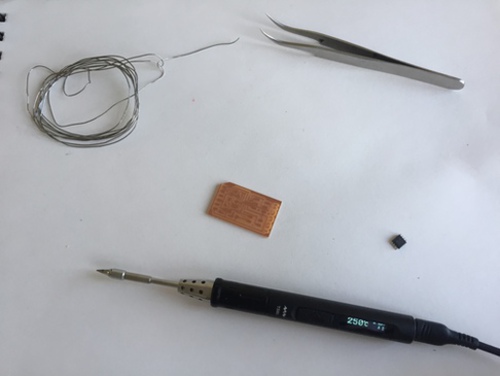
Stuffing it was easy- very few components. The new soldering iron was a bit inconsistent though, I kept having to turn the temperature up just to maintain the same heat. I went from 270-340 over the course of soldering.
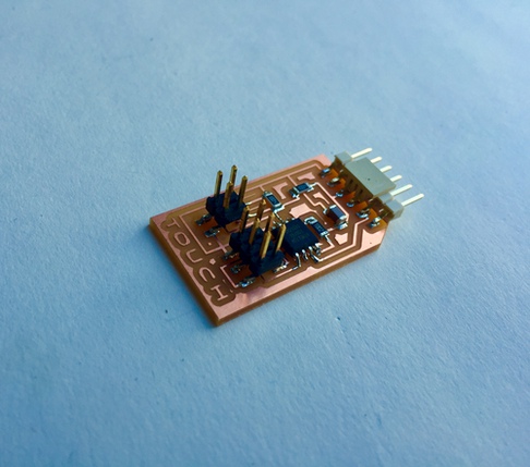
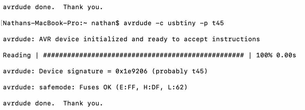
I then hooked the board up to my computer using the tinyISP we had made in week 5. My computer could find it:
I then copied the c file Neil wrote for the board and copied it into a new Arduino file. In tools, I selected Attiny as the board, tiny45 as the processor. I compiled the code, and uploaded it successfully. I then downloaded the python file Neil wrote to operate the board and get a readout on the computer. I placed it in a directory, navigated to that directory in terminal and attempted to run it using the command:
$ python hello.txrx.45.py /dev/tty.usbserial-[my serial port number here]
However, I kept getting the following error:
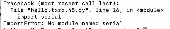
I googled this error, and learned that I should download pySerial. I did so using
pip3 install pySerial
It installed successfully, but when I tried to run the file, it produced the same error.
Henk told me the problem was likely that I was trying to run the file with a command starting with python instead of python 3, as I had already installed pySerial for python3.
I tried python3 hello.txrx.45.py /dev/tty.usbserial-DN05BTJ9 and… the error disappeared! But now I had a new one
File "hello.txrx.45.py", line 15, in <module>
    from Tkinter import *
ModuleNotFoundError: No module named 'Tkinter'
It seemed like pip3 install Tkinter would solve it as this was the same error as with pySerial....but no luck.
ERROR: Could not find a version that satisfies the requirement tkinter (from versions: none)
ERROR: No matching distribution found for tkinter
After looking online I found pip3 install tk to work. But when I ran the program, same importError.
Henk told me to change the line of code in the file to tkinter rather than Tkinter- it is lower case for python 3.
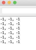
Finally, this got it running, and I was getting variance when I touched the pins, so all seems to be working.

Now figuring out how to connect to the copper pads… Because the transmit-receive pins in the design lead to a 4 pin header, I assumed all 4 pins would be used. I kept taping 2 pins at a time to the pads, but the python readout would either fall to Zero, go all over the place, or stay too high. I read a bit more about the basic principles of step response to try to figure it out, and mainly read this fabacademy site:
Suddenly, it dawned on me that the two pins kind of make a complete circuit, and it is the addition of a person’s hand that completes the circuit and makes the change in signal. (my very basic understanding of step-response) So I only needed one pin on each pad. When I had this thought, I looked at other step response project pictures, and realized this is what others were doing as well. I connected only the pins that led to the microcontroller, one to each pad, and it worked!
Final video:
Summary
I was a bit distracted this week because of corona, but glad I got an input device working, even though I could have a better understanding of how it works. I definitely think I will use Arduino libraries with devices in the future, as I did not feel I could even begin to play with Neil’s code, and the arduino library commands helped me understand how the devices worked with the ones I connected to the NodeMCU, like the accelerometer. As X Y and Z were separate, I understood these were different pins on the device, etc.