9. Embedded programming
individual assignment: read a microcontroller data sheet program your board to do something, with as many different programming languages and programming environments as possible group assignment: compare the performance and development workflows for other architectures
ESP 32
This week I decided to read the datasheet for the ESP 32, as I want to use it for my final project.
The data sheet can be found here.
Notes
The data sheet is 52 pages. As this is not long compared to say the Attiny 44, I will read the whole thing. I am including notes I found interesting here:
1.1.1
In this opening section, I was surprised to read that they first list that the ESP is designed for mobile, wearable electronics, and then go on to explain its low power usage. I guess this makes sense, as the change in power consumption from esp8266 to esp32 would largely benefit mobile, rechargeable batteries.
The chip has both WiFi and Bluetooth capabilities.
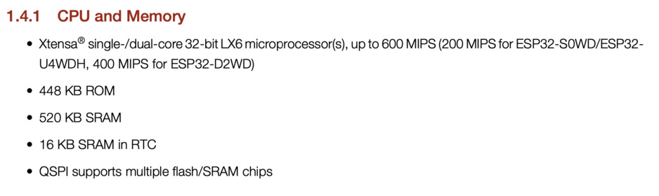
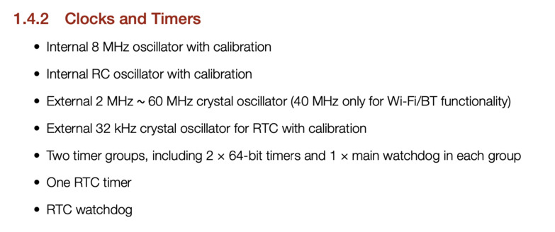
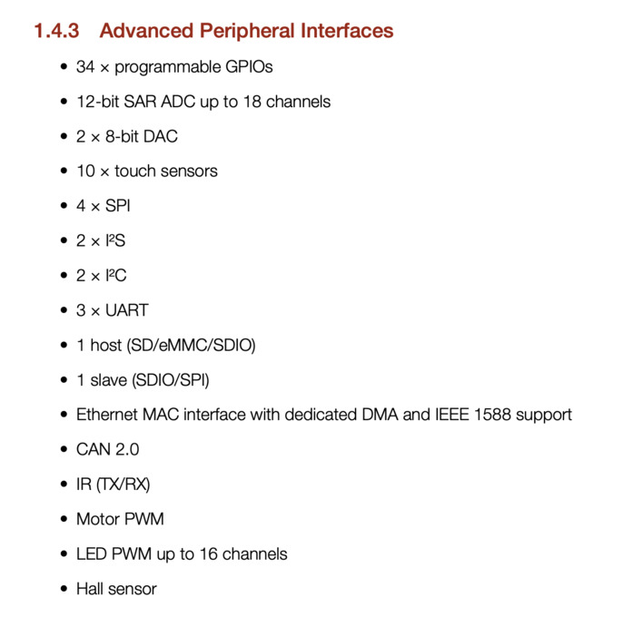
I am including screenshots from the sections which describe CPU and Memory, as well as clocks and timers and peripheral interfaces here, as I will likely need to refer back to these as I design my final project.
1.4.1 CPU and Memory
1.4.2 Clocks and Timers
1.4.3 Advanced Peripheral Interfaces
1.6 Block Diagram
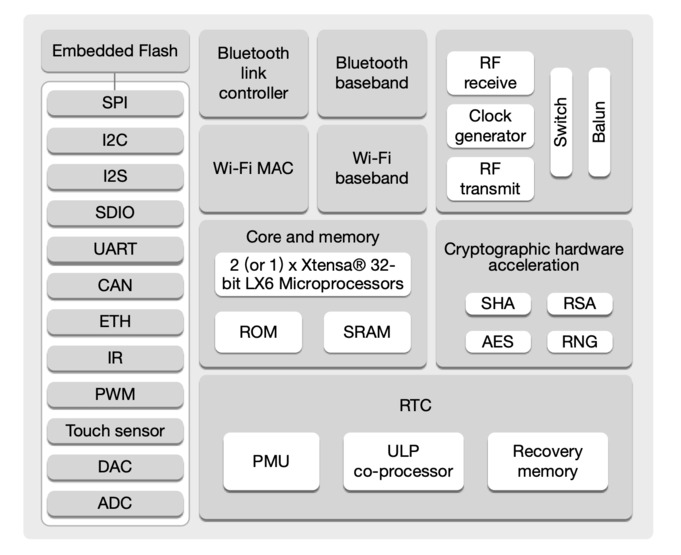
Here, I know I will use the ULP co-processor. This is one of the new features of the ESP32, as it is what still runs in deep sleep mode.
I will additionally connect the E-Ink display with SPI, and the accelerometer likely with I2C.
2.1 Pin Layout
The ESP has 34 accessible pins.
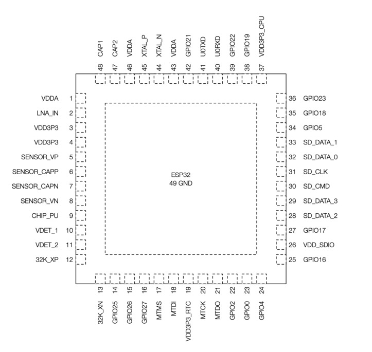
It has 4 different SPI bus connections on the chip. I will need all 6 SPI pins to connect an E-Ink display, in addition to two power supply pins. In the data sheet, they mark these groups of SPI connections with a different starting letter on each, such as SPI, HSPI, and VSPI. An example connection I could make is using all of the standard SPI pins:
GPIO9 - SPIHD GPIO10 - SPIWP GPIO 11 - SPICS0 GPIO 6-SPICLK GPIO 7 - SPIQ GPIO8 - SPID
As you can see in the chart, these are all multiplexed with other connections, such as SD_DATA
Additionally, these are all grouped under VDD_SDIO
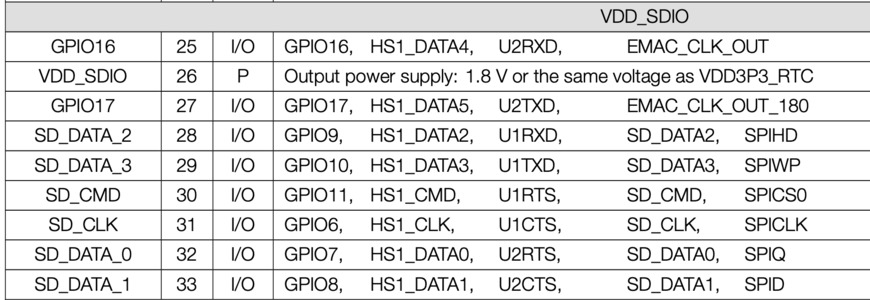
The distinctiuon is that each grouping of pins works on a separate internal power supply, as described here
“VDD_SDIO connects to the output of an internal LDO whose input is VDD3P3_RTC. When VDD_SDIO is connected to the same PCB net together with VDD3P3_RTC, the internal LDO is disabled automatically.”
In describing the power supply, they state:
"An additional discharge circuit may be required to accelerate the discharge of the large capacitor on rail VDD33, which will ensure proper power-on-reset when the ESP32 is powered up again."
This seems to be the case when looking at Neil’s “Hello ESP32 Wroom” board, as all he really adds is a reset button, as well as a switch that allows GPIO0 to be pulled low or high, which switches from programming mode non programming mode.
2.4 Strapping Pins
I dont know what strapping pins are, but was curious as the datasheet spends a couple of pages on this. On the ESP32, they are:
MTDI GPIO0 GPIO2 MTDO GPIO5
And software can read the value of them from register “GPIO_STRAPPING”
I looked up what strapping pins are, and found a description on the ESP32 site.
Basically, these pins sample their voltage value as either 0 or 1 at start up, and hold on to that value, controlling some aspect of the board’s performance. GPIO0 defines programming or run mode, for example. If 12 is pulled high, even in programming mode, it will prevent program writing, etc. All of these pins are important to keep in mind when debugging, to make sure no connections on the board are interfering with programming.
3.1.4 Memory Map
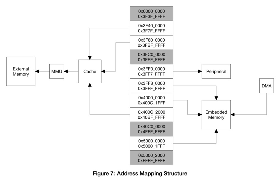
While I don’t fully understand the differences between all of these types of memory, I know that in ESP_tool, for example, you can write to these specific flash addresses by writing them out in a write command, so I want to include this section in my notes instead it comes in handy while programming.
3.3 System Clocks
The ESP32 has an MHZ oscillator. Upon boot, it will automatically attempt to connect to an external oscillator, and if not will use the internal oscillator.
3.5.1 Wi-Fi Radio and Baseband
The ESP32 Wi-Fi Radio and Baseband support the following features: • 802.11b/g/n • 802.11n MCS0-7 in both 20 MHz and 40 MHz bandwidth • 802.11n MCS32 (RX) • 802.11n 0.4 μs guard-interval • up to 150 Mbps of data rate • Receiving STBC 2×1 • Up to 20.5 dBm of transmitting power • Adjustable transmitting power • Antenna diversity
ESP32 supports antenna diversity with an external RF switch. One or more GPIOs control the RF switch and selects the best antenna to minimize the effects of channel fading.
3.5.2 Wi-Fi MAC
The ESP32 Wi-Fi MAC applies low-level protocol functions automatically. They are as follows: • 4 × virtual Wi-Fi interfaces • Simultaneous Infrastructure BSS Station mode/SoftAP mode/Promiscuous mode • RTS protection, CTS protection, Immediate Block ACK • Defragmentation • TX/RX A-MPDU, RX A-MSDU • TXOP • WMM • CCMP (CBC-MAC, counter mode), TKIP (MIC, RC4), WAPI (SMS4), WEP (RC4) and CRC • Automatic beacon monitoring (hardware TSF)
3.7 RTC and Low-Power Management
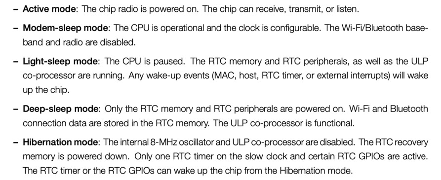
I am especially interested in this part, because I want to be able to put the board in Deep Sleep mode or even hibernation mode when I am not actively programming it or changing what is on the display.
This will depend on how I can wake it up- I likely want to do this with one of the touch pins. For hibernation mode, it describes that certain RTC GPIOs can wake up the chip- i am curious if any of these overlap with the touch pins. I looked back at the touch pins, and they do overlap! GPIO 10, 11, 12, 13, 14, 15, 16 and 17 are all both GPIO and touch. I will look into this more when I learn about programming for low power modes.
4.1 Description of Peripherals and Sensors
“ESP32 has 34 GPIO pins which can be assigned various functions by programming the appropriate registers. There are several kinds of GPIOs: digital-only, analog-enabled, capacitive-touch-enabled, etc. Analog-enabled GPIOs and Capacitive-touch-enabled GPIOs can be configured as digital GPIOs.”
4.1.5 Touch Sensor
“ESP32 has 10 capacitive-sensing GPIOs, which detect variations induced by touching or approaching the GPIOs with a finger or other objects. The low-noise nature of the design and the high sensitivity of the circuit allow relatively small pads to be used.”
I will want to try to use these, and I like that they can be used with small pads, as I will want to give my final project some discrete touch controls. This section is followed by the part I will want to use these with:
4.1.6 ULP Co-Processor
“The ULP processor and RTC memory remain powered on during the Deep-sleep mode. Hence, the developer can store a program for the ULP processor in the RTC slow memory to access the peripheral devices, internal timers and internal sensors during the Deep-sleep mode. This is useful for designing applications where the CPU needs to be woken up by an external event, or a timer, or a combination of the two, while maintaining minimal power consumption.”
I am picturing that I will wake the board up with a touch pin in order to program it, or in order for it to get its position via an accelerometer. So hopefully I can store the commands for this in the ULP. The e-ink display does not consume any battery when resting, so I am aiming for ultra low power consumption overall.
4.1.11 I2C Interface
This section does not tell me much about I2C, except that it has standard or fast mode on the ESP32. I do not think this concerns my applications, but will be curious if I run into this
4.1.17 Serial Peripheral Interface (SPI)
Similar to I2C, this section did not tell me anything new about SPI. It again lists that the ESP32 has 3 different kinds of SPI: SPI, HSPI, and VSPI. because it does not describe differences between these, I assume they are just labeled differently but essentially function the same.
The rest of this section is a many page chart, which describes all the multiplexed capabilities of each pin for the peripheral device applications described in this section.
5 Electrical Characteristics
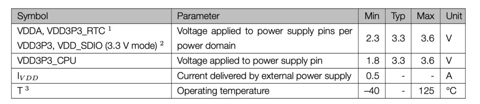
The board can operate between 3.3 and 3.6V, which is why a voltage regulator is required when connected to USb power, as seen on Neil’s board.
The datasheet closes out with charts with even more detail on each Pin.
Tutorials
Tinkercad
I wanted to get a very basic understanding of programming and how to communicate with the board, and because my own helloecho still didnt have a working LED, I decided to play around on tinkercad before trying to do something with my board and button.
I worked on different arrangements with the Arduino and added components, and through these it became a lot clearer to me how microcontrollers work, and how to communicate with them with code.
Tinkercad has a code block editor, where commands can be dragged and ordered as blocks, and the way you arrange these blocks then generates a code.
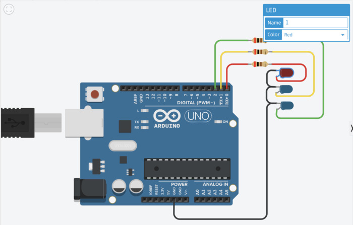
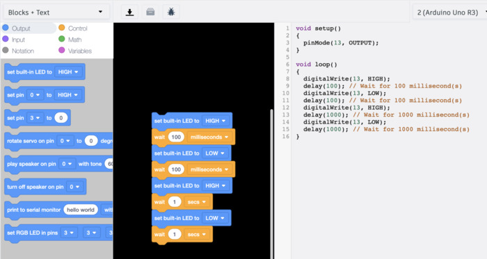
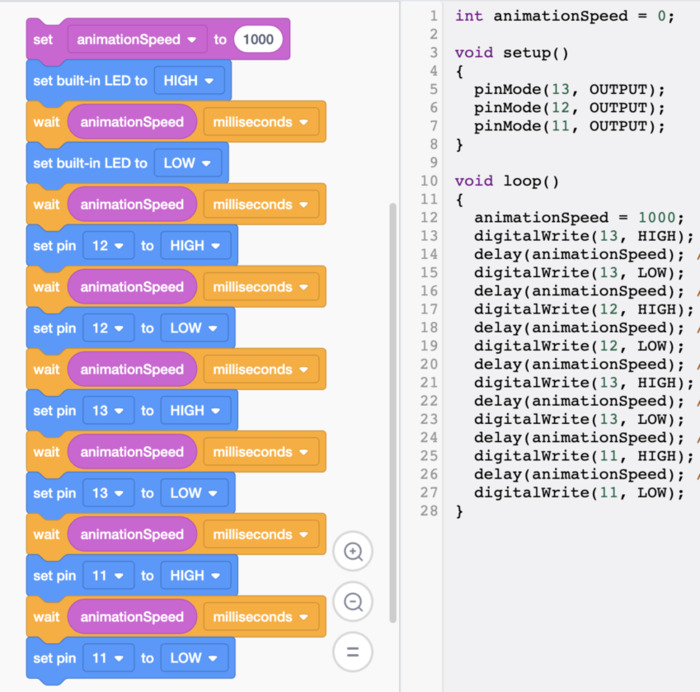
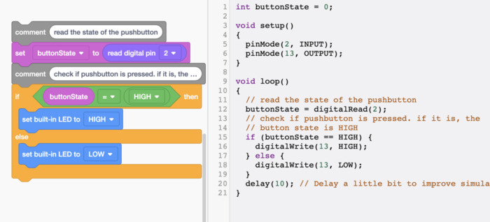
Though I used arduino a bit about 5 years ago, working in this graphic layout for a while really helped jog my memory. I liked how they had delays, on/off etc as blocks, that i could then see as code, so i could get an idea of the structure and what the basic commands are.
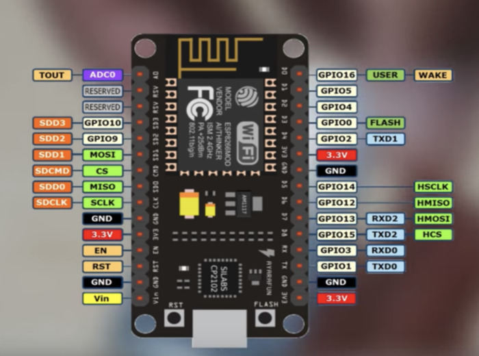
NodeMCU
Next, I wanted to try to use the NodeMCU board. This is the ESP8266 microcontroller it uses:
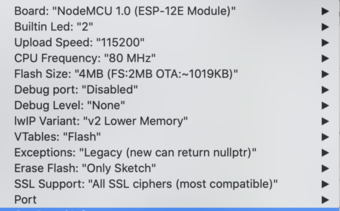
To do this, I had to change some settings in Arduino. I first added the line
https://arduino.esp8266.com/stable/package_esp8266com_index.json
I then selected the board from the Tools menu in Arduino as the one I would be using.
and then ran blink on it…and it worked, easy.
Note: When I adjusted the delays, however, it appeared the two commands were somehow reversed. “HIGH” ran as off, while “LOW” ran as on. However, if I placed Low before High in the loop, I could get it to operate correctly.
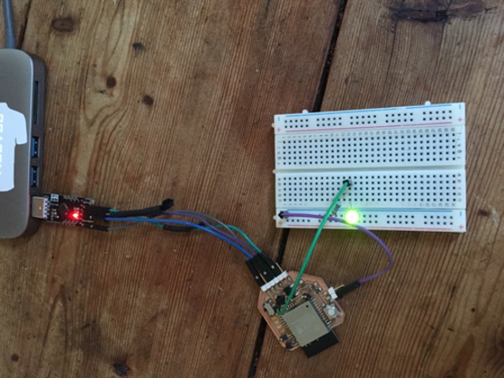
I then ran the code through one of the other pins and connect an LED to the breadboard, so I could begin to do more with the board. That worked, so I added a button.


Arduino IDE
I then wanted to compare a couple of platforms using a board I made. I am doing thse tests using the board I made for my final project
I am more used to using the Arduino IDE and find it easy. The basic principles are to make sure to have a link to the board libraries in the preferences pane.
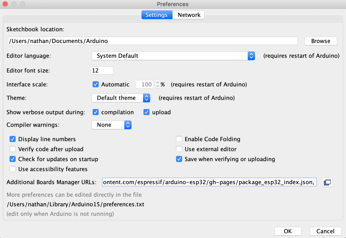
For the ESP32, those are:
https://raw.githubusercontent.com/espressif/arduino-esp32/gh-pages/package_esp32_index.json
An arduino file is called a ‘sketch.’ Premade sketches can be found in the File > Examples tab.
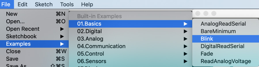
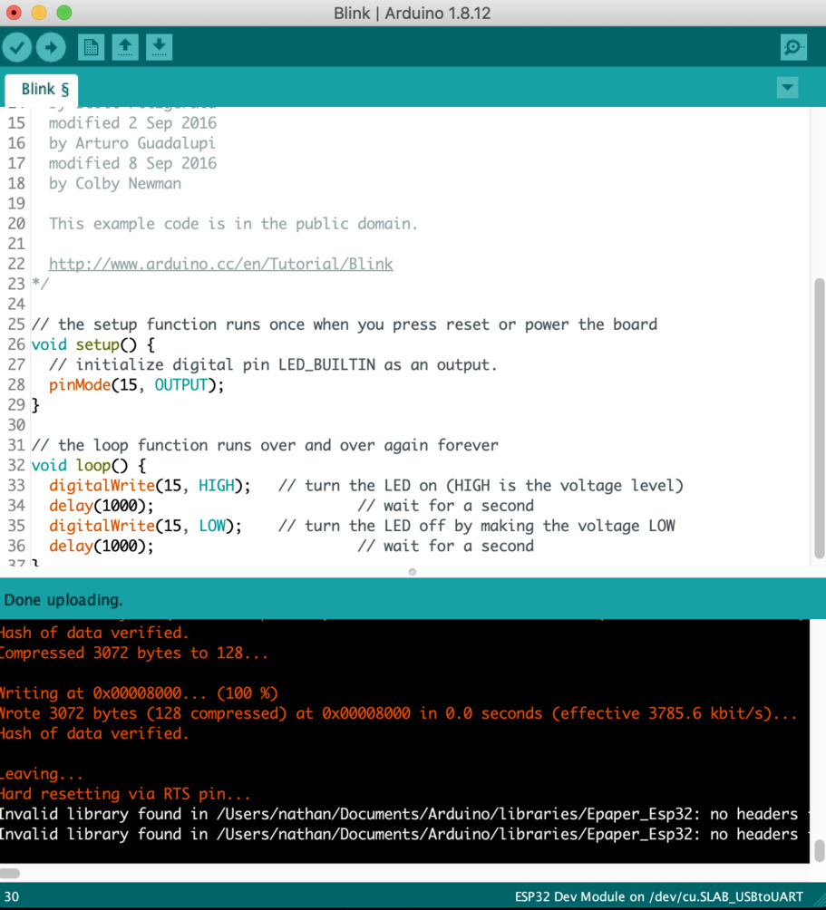
I used blink, as I wanted to compare the same sketch in a few platforms and thought this would be easiest.
After opening the sketch, you can select the board you are using from the ‘tools’ menu. For the esp32, the correct settings then automatically are chosen in the rest of the tools options.
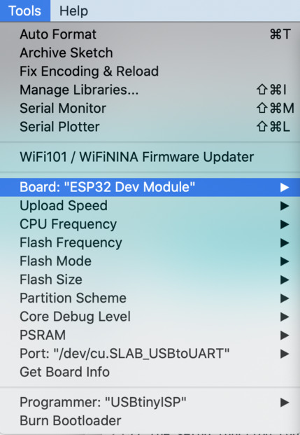
I am able to access esp32 in this menu because of the JSON link from the preferences pane.
Upload and compile are the check mark and arrow buttons in the top left corner, though upload will also compile when clicked. Blink compiles and uploads successfully!
PlatformIO
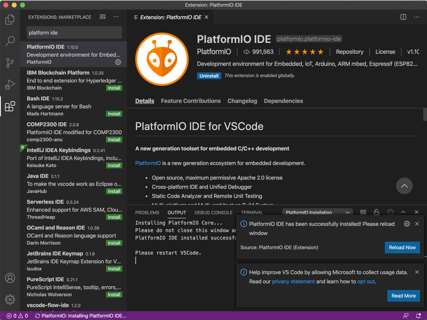
Upon going to the Platform IO site, I had not realized that this was an app within VSCode.
I downloaded VSCode, opened it, and typed Platform IDE in the search bar, as instructed on the PlatformIO quickstart page.
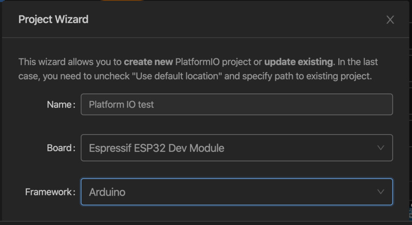
I then clicked New Project, and chose ESP32 as the board.
I was then presented with a tabbed screen and menu bar on the left.
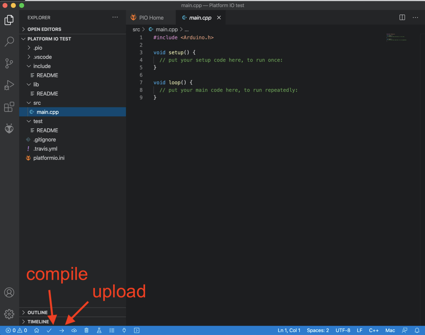
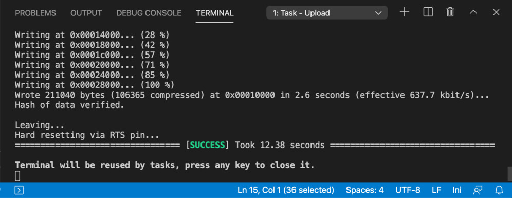
I then copied the blink sketch from the upload page into the main.cpp file as it suggested. I tried clicking compile, and it worked! But when I tried clicking upload, I ran into an error. It seemed it was trying to use the wrong port. I could not find any menu where I could change port.
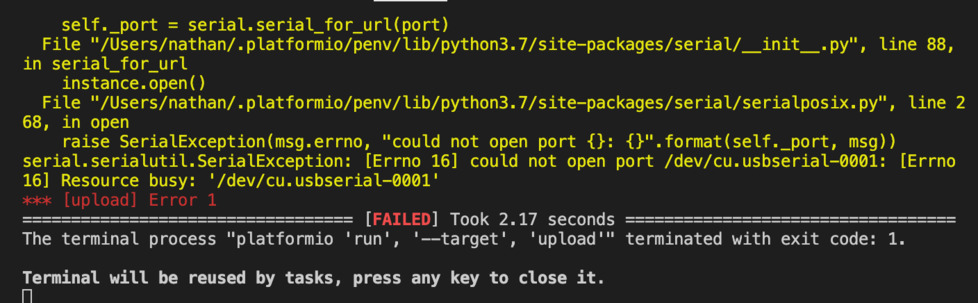
After doing some googling, I found that this could be changed manually.
What could more or less be used as the ‘Tools’ menu in Arduino was the platformio.ini file. This can be found in the project files on the left menu bar. With this, I could manually enter some of the settings I needed, and saw the board was already listed here. This page gave info on how I could do that.
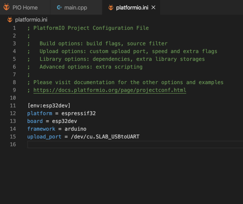
I added the line
upload_port = /dev/cu.SLAB_USBtoUART
I liked that platformIO seemed very flexible. Being part of the VSCode environment, it would be easier to use micropython or other languages than in arduino. That being said, I am still new to this stuff so will more likely sticck to Arduino.
Summary
I found reading the datasheet helpful— though i didn’t understand everything, I started to pick up on the basic process of seeing what you want to do, looking for the connections you need in the datasheet, then programming accoridng to those connections.
I will likely stick with Arduino for the remainder of fabacademy, as it has the most documentation and appears the most on previous documentation, so it will be too much to take on other environemnts until it is easy for me to work with Arduino. Tinkercad will be a helpful refresher for basic commands if I cannot find them elsewhere.