4. Computer controlled cutting
How to Use the Laser Cutter
Our laser cutter is a CO2 laser, brand BRM. Rutger introduced us to the laser, and showed us how there is a machine in the back that keeps the laser cool with mineral water. This machine should display a constant temperature of 23 degrees.

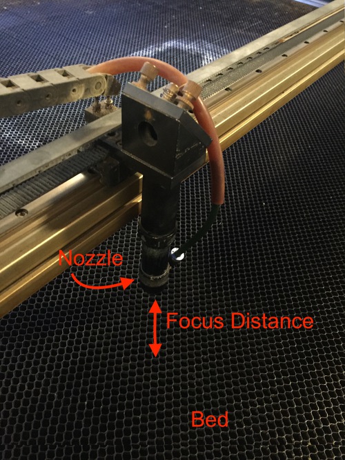
The bed is 160x110cm. There is a focus block we can use to set the focus by loosening the laser nozzle and changing the distance between the laser and the surface being cut. Sometimes, when cutting thick material, you can notice the cut begin to slope as the beam gets out of focus.
Using the Software
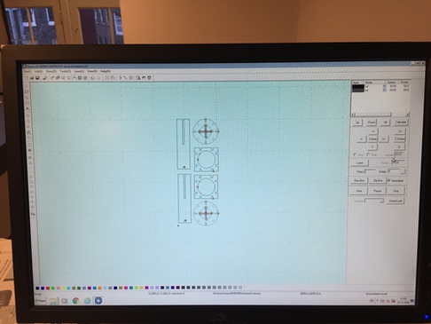
First, prepare the file inside of the software.
- Open Lasercut 5.3
- Import your file from a thumb drive in formats .ai(CS2) or .dxf(from inkscape only)
- Check dimensions with size tool
- Edit > Center to table
-
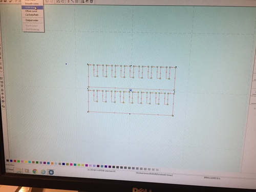
Drag and select all, then Tools > Unite Lines. This turns the design into a single path for the laser cutter so that it its more likely to move continuously.
-
Laser > Set laser origin (usually set to left top). After anchoring the laser head on the machine, this will determine the direction the nozzle travels in when drawing the design.
-
Different lines can be selected and assigned a new color in the menu on the right side of the screen. Each color is then listed in this same panel. Double click on a color in this panel to set the Speed and Power at which the laser will cut lines of that color.
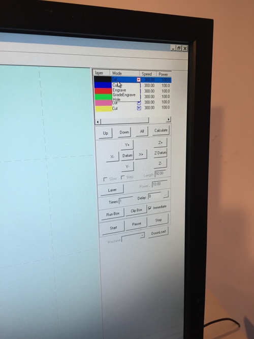
-
In the same dialog box as above, corner power can be set separately as the machine slows at corners. 20 is a good general setting
- Press download at the bottom of the right side of the screen. Click Delete All, then Download current. The Machine should be on for this step
Using the Machine
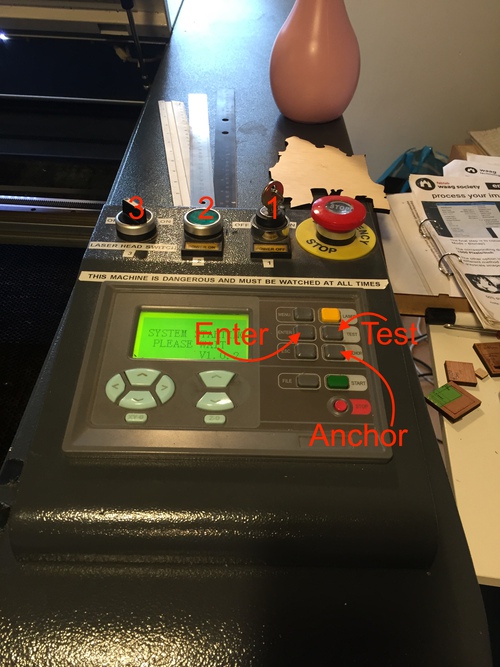
- Machine ON with key
- Green button
- At this point, you can guide the laser to the desired starting point on the bed using the four arrow pad on the machine. Note that it is NOT the arrow pad for the Z axis, which only has two arrows. If it doesn’t move, hit Escape on the laser and try again. Move it to the origin point, then press Anchor, followed by enter.
- Laser Head switch (turns on cooling as well)
- Press test and the laser head will trace the outline of the area of the design.
- Make sure laser cutter is closed. Use two hands to close it
- Turn on exhaust (switch below computer)
- Press start to start the job
- Pressing start again will pause the job. Stop stops it entirely.
Notes and Safety
- Don’t leave the platform that the laser cutter is on while cutting
- There is a spray bottle next to the laser in case of fire.
- pause sometimes when using acrylic, as the whole sheet can heat up
- Cut nexted shapes first so they don’t warp while cutting
How to Use the Vinyl Cutter
- Start the computer and hold F2, then choose to boot up in Windows 7.
- Load material into the cutter from the back.
- Pull handle on the back up to lock material in
- Keep pressing origin until the machine says it is set
- It sets width automatically
-
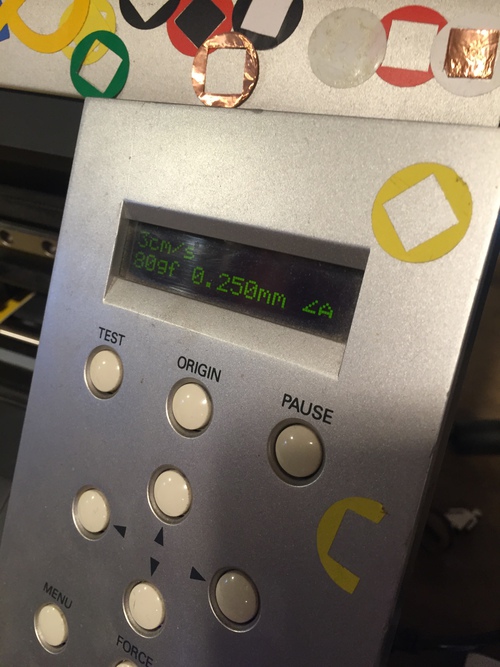
3cm/s, 80gf/force, .250 thickness are the settings that will typically be there and generally work well
-
Hold test until the machine cuts a test shape
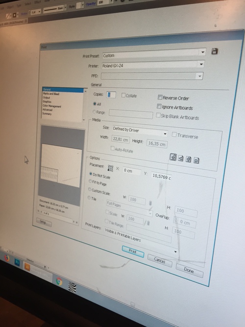
- Go back to the computer and open Illustrator. Always use 1pt line, vector is better
-
File and print
-
Check do not scale on the print dialog, and select bottom left placement
- Send print
- Peel off parts of the print you dont need
- Rub transfer film on the remaining parts, then pull off the backing paper from the vinyl
- Apply to where you want it, rub down, and remove transfer carefully.
We can also use mods in Ubuntu, but I did not fully understand this and used illustrator this week.
Group Assignment
For the group assignment, I worked on characterizing our machine’s focus. I quote my description of the process here:
Focus
To determine the laser cutter’s ideal focus distance, we had to run an experiment to find the distance between the laser head and the material being cut at which the beam from the laser was the smallest.
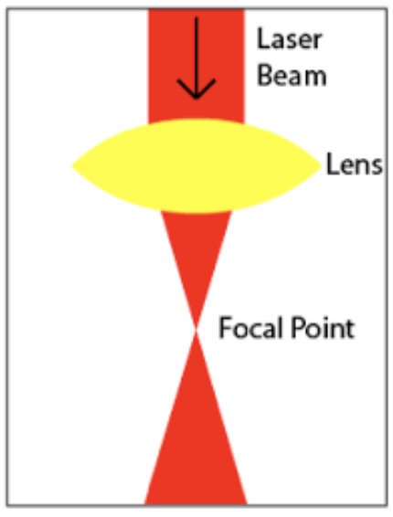
The laser beam is reflected off of mirrors to focus at a single point. The beam is wider both before and after the focal point, forming an hourglass shape, seen in the picture below.
I googled how to find this point, and a quick survey of the results suggested that there are two basic methods to find the focal point.
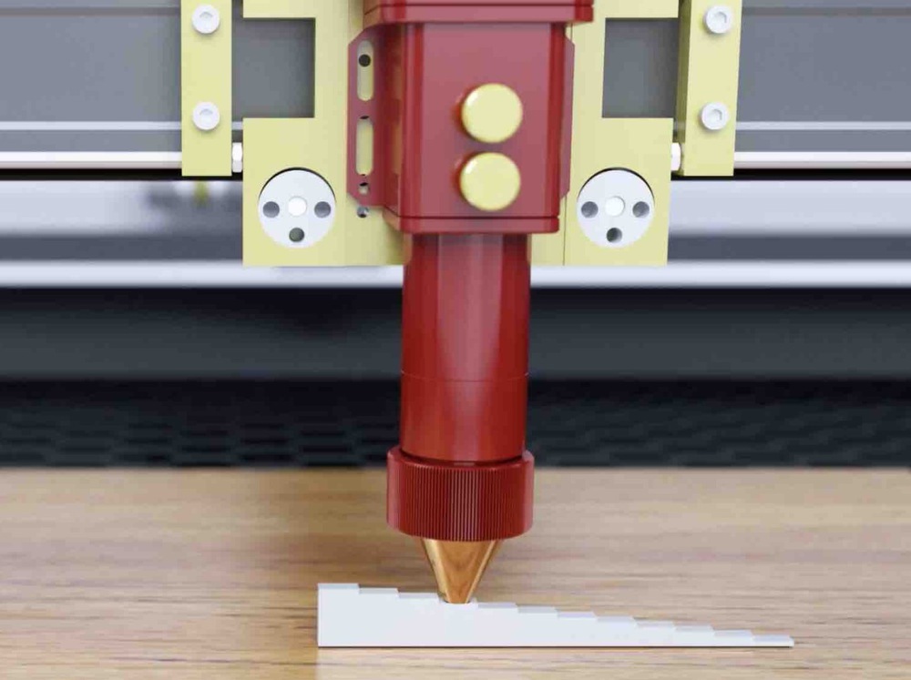
The first involves increasing the laser head by increments of 1mm, and carving a line with the laser after each adjustment. However, such a test requires a tool which allows you to precisely measure the distance between the head and the material. Something like the one seen in this video from BRM:
Other guides that used this method had similar measuring tools, with a different individual block for each mm increment. We had no measuring tools with this capability at Waag, so we had to go with the second method. For this method, a ramp needs to be created in the laser cutter. The laser should then be set to draw a line across the length of this ramp. This line will vary in thickness, and the point at which the line is the thinnest is the point at which the laser is at the ideal distance from the material’s surface.
Here is an example instructional video of the method.
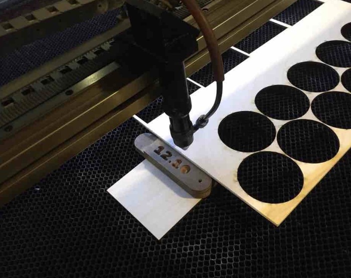
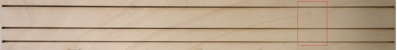
We set up our ramp using a piece of scrap wood, and propped it up on some other pieces of wood found around the lab. At its highest point, the ramp measured 27mm in height. We decided to draw three lines down the length of the ramp, all at speed 30, and at power settings of 20, 30, and 50, with the laser cutter set to ‘Cut.’
We set the laser head to 4mm distance from the ramp at its highest point, and had it draw lines of 48cm (the wood was 49cm).
The lines were the thinnest in the range of 9-13cm down the ramp.
I had to relearn some algebra in order to find what this meant the focus distance was. While the highest point was 27mm, the point 480mm down the ramp was not at a height of 0, but about 4mm, or the height of the wood at the lowest point of the ramp.
This means I first had to characterize the triangle created by this ramp, I then used that triangle to solve the distance between the surface and laser head at the point where the line was most thin. I calculated using 11cm as the distance the laser had traveled before reaching optimum focus, as it falls in the middle of our range of 9-13cm. The math I used is pictured below:
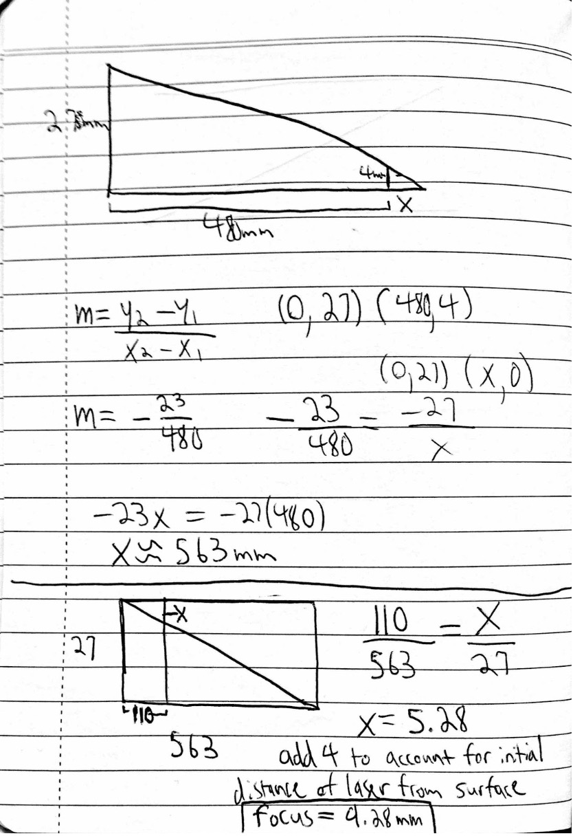
If we account for the entire range on the lines that the laser was in focus, this means ideal focus distance is between 8.3mm and 10.3mm.
We also used a bit more crude method. Before removing the ramp from the laser cutter, we moved the head back over the thinnest point of the line, and Harm attempted to measure the distance between the head and the wood using digital calipers. This measurement was 11.6mm.
The tool Waag uses to set focus distance places the head 12.10mm away from the material. We wanted to test our results against this number and see which is more accurate, but unfortunately did not have time to do that this week.
Parametric Construction Kit
My initial idea for this week was to make a bag that could take different forms by making an entire sheet of cardboard a living hinge, and then making different shapes to wrap it around. I then thought I could add wheels to these bags and make a transformable luggage set. I wanted to start as simple as possible, however, so I decided to make the wheels first as I figured the living hinge would be a bit more difficult and use more cardboard.
I searched the FabAcademy archive for previous projects that involved wheels in the parametric construction kit. I found this project and thought these types of shapes would be easy to replicate as a start:
I hoped that once I got these working, I would be able to make bags to attach to them later in the week.
However, I realized making a parametric design was not as easy as I first thought. I immediately ran into trouble placing constraints on even a simple circle with rectangles cut into the sides. Every time I changed a parameter, it would deform the circle. Here is an example:
Finally, I got it working. After I sketched the second shape, however, I changed a parameter and the first shape would not change at all. It took me at least an entire day of experimentation to get into a good workflow with sketch mode in fusion. I had remembered the software as more simple from the first week.
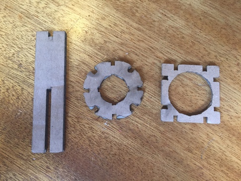
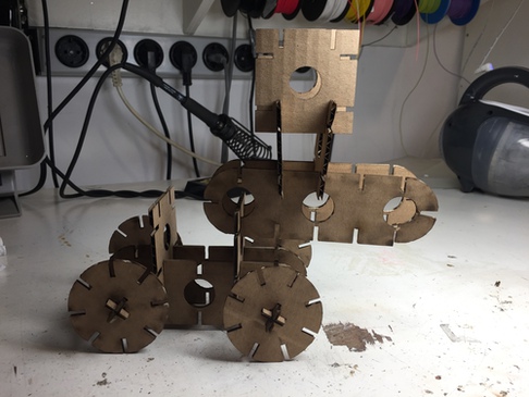
The first few shapes I made were a wheel, axel, and square that this axel could fit through.
I used the steps outlined in the section on lasercutting at the top of this page. I cut at a speed of 30 and power of 50. I was happy with how these settings cut, but I thought I should increase the speed if I had a bigger cut in the future.
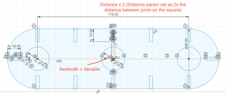
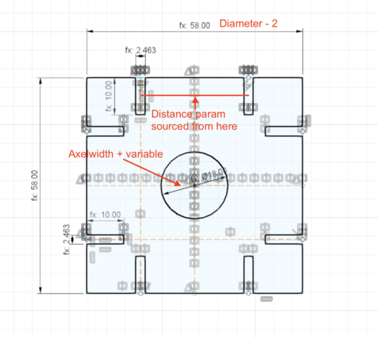
The pieces fit together, but the hole for the axel seemed too large, and I wanted a shape longer than the square. To make the size of the hole in the square parametric, I added the parameter Variable and changed the diameter of this center circle to Axelwidth + Variable.
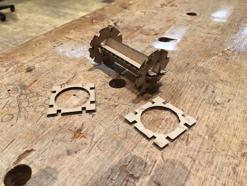
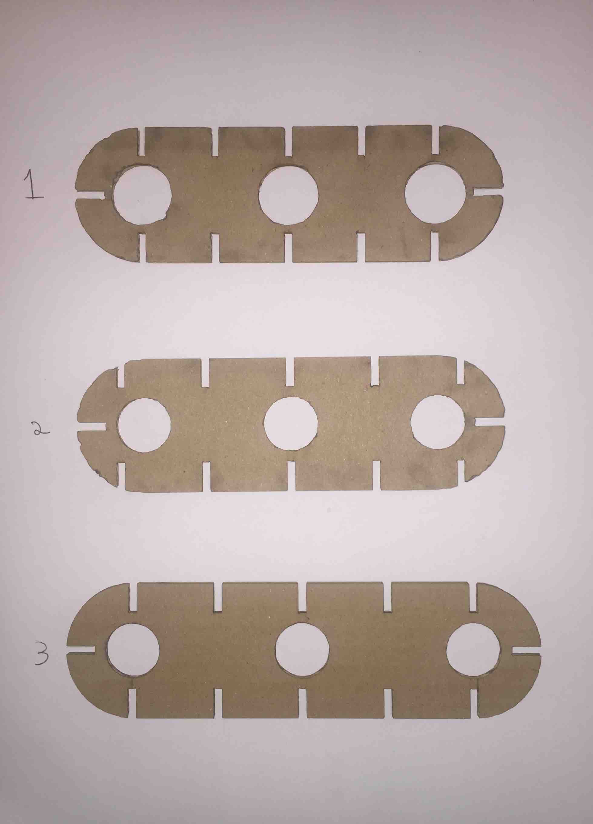
I decided to make a slot with three holes and joints all around the perimeter. I did not know exactly how this would work, but I liked that it offered either height or length, and and that it could connect multiple sets of wheels on its own.
This ended up being quite time consuming. I borrowed the Axelwidth+variable diameter for the central circles, but otherwise just guessed at howe everything else would work. In the first model, I did not think to make the spaces between joints the same distance between joints on the square shapes I had made. This meant that when I had two squares next to each other in the slot, I could not then attach a square perpendicular to them.
In the second version, I spaced the joints correctly, but then realized the design lost some flexibility if the joints were not even with the holes.
Finally, I made the slot longer to account for the squares and to have the joints line up with holes.
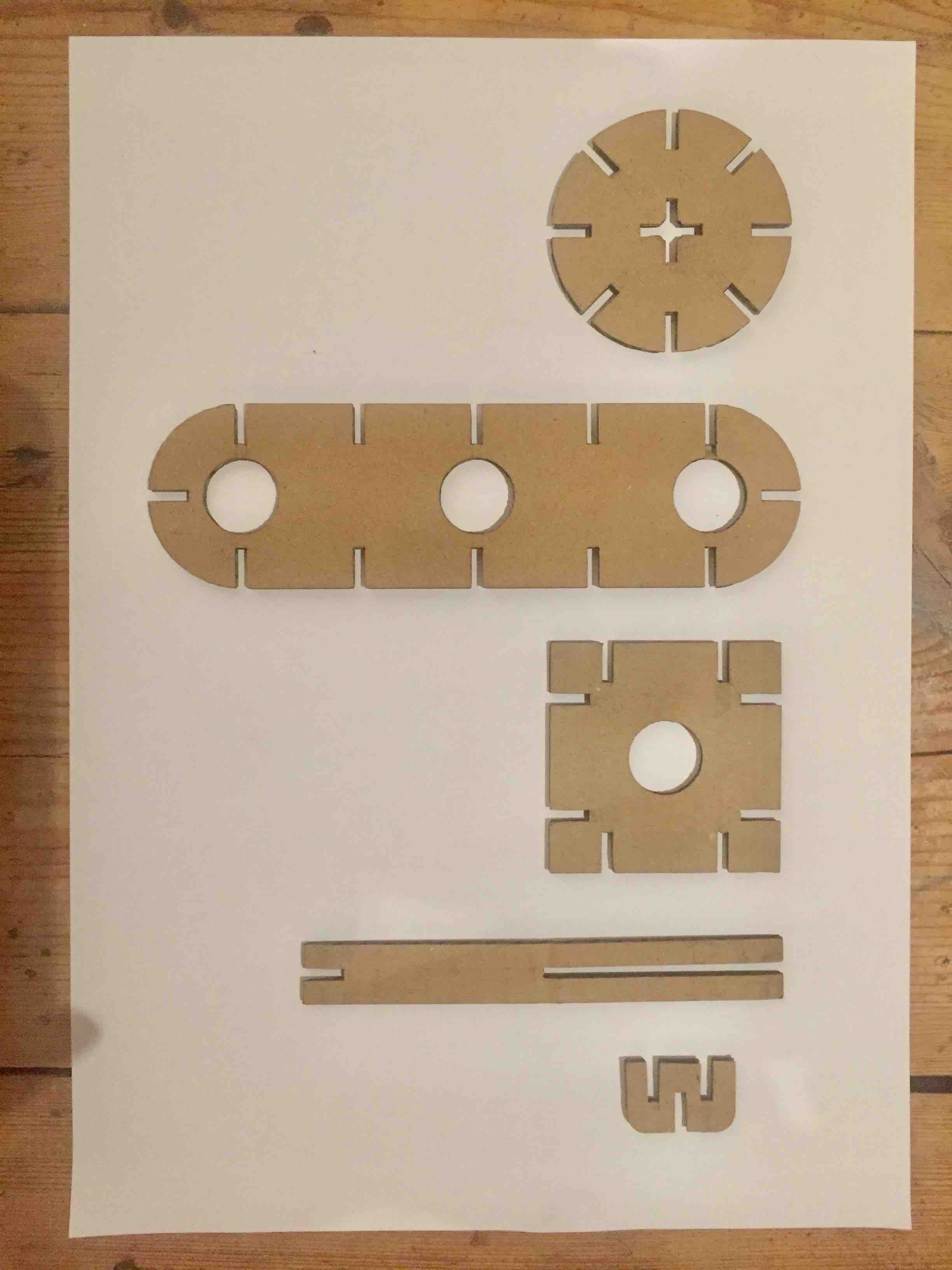
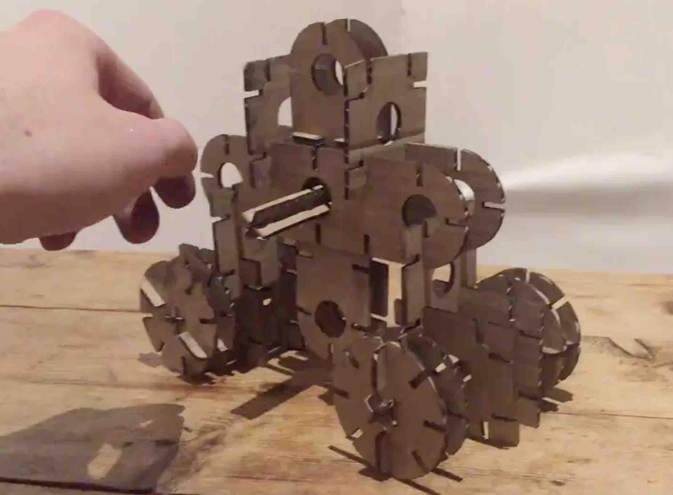
These are all of the shapes I ended up with in my kit.
I only had the first 4 at first, and these were a couple of my first constructions:
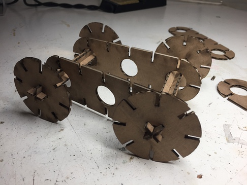
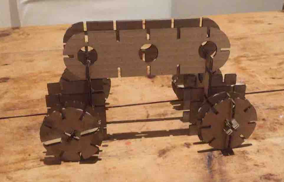
In the next image, you can see the problem with the spacing between joints in the original body. The two squares are attached at an angle.
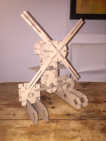
On top of the issues with the body, the wheels still felt too flimsy to me, so I wanted to make another shape that could connect two wheels together to make a bigger wheel to provide more stability. I also added another joint facing outward to this new shape, as I had been imagining I could do a windmill variation with these shapes and realized this would allow me to place the blades.
Though I had to give up on the bag idea because of time constraints, I ended up having a huge amount of flexibility with these shapes and am very happy with how they turned out.

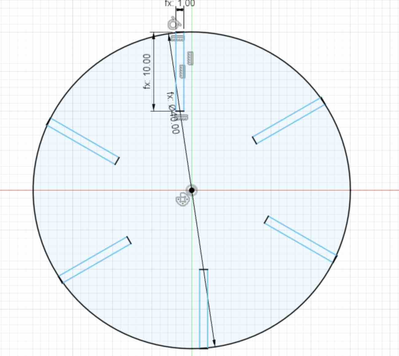
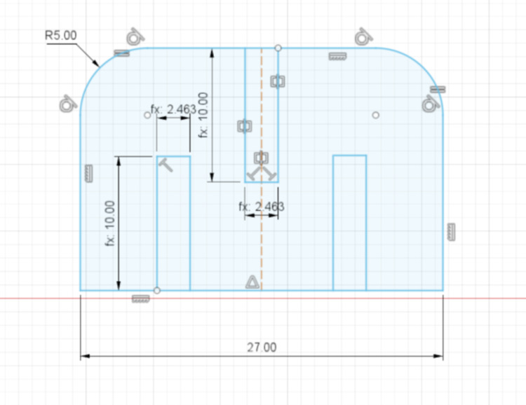
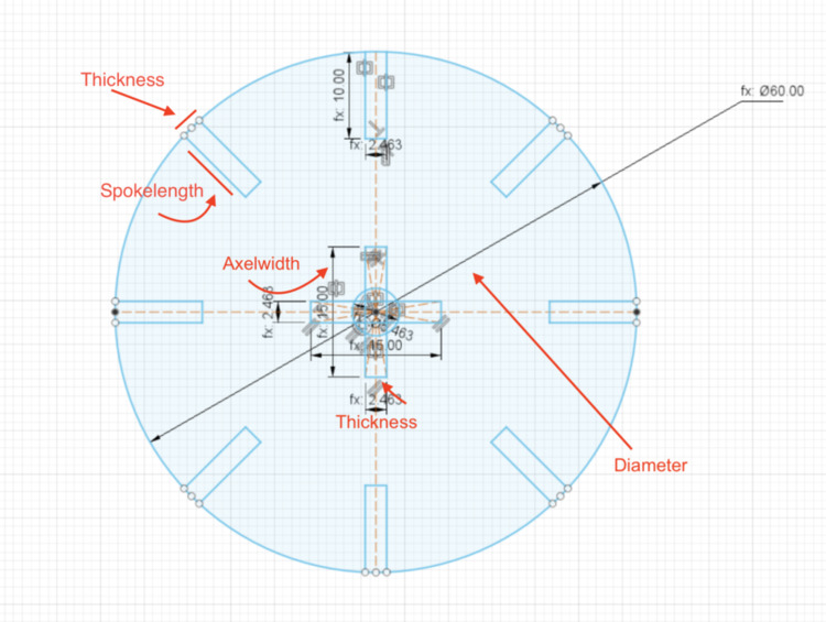
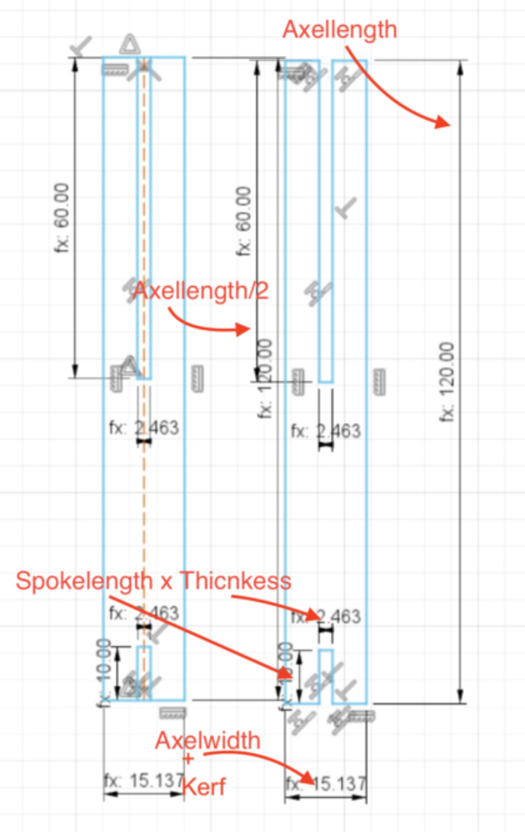
In the final version of my designs, here are all the parameters I used:
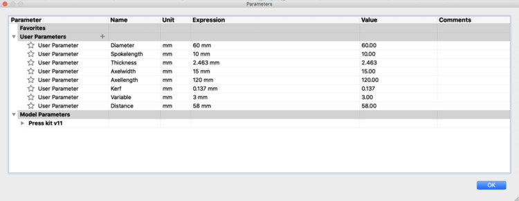
I labeled where I use them in the sketches below, some repeated from above.
Vinyl Cutting
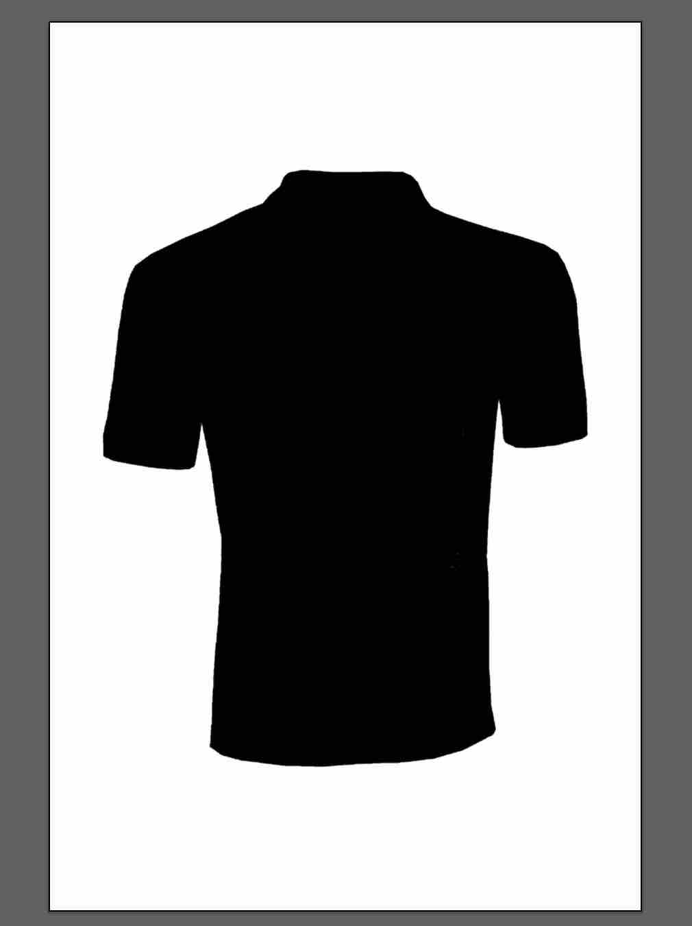
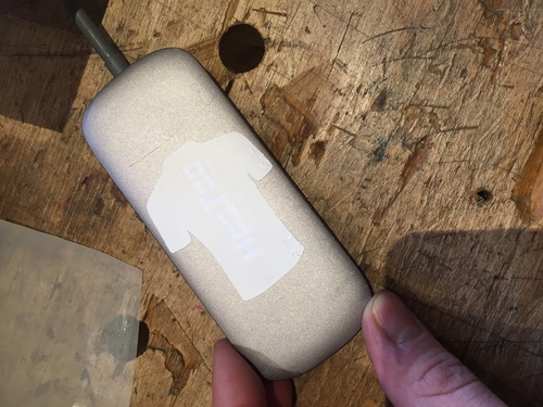
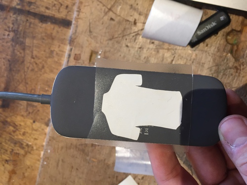
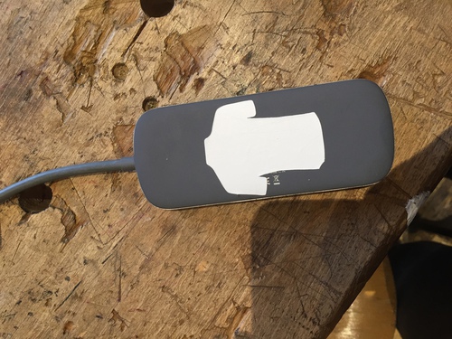
I made one very simple sticker on the vinyl cutter this week. I screenshotted an image of the silhouette of a t shirt from the internet and then saved it as an .ai file.
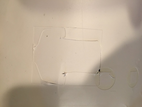
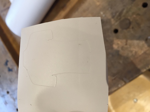
When I first followed the steps I describe in the above instructions for the vinyl cutter, the machine did not do anything. I then made the image a vector using image Trace. This worked, but the machine went over the lines twice and cut through the vinyl backing. I zoomed in, and realized image trace had made two lines that were on top of each other. I deleted one. This fixed the problem.
I then ran into trouble again when transfering the image- it was very stuck to the transfer material! Afterward, I asked someone in the lab about the material I was using… turns out it wasn’t the correct transfer.
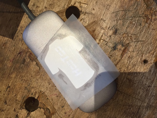
Luckily, I had the first print that the machine cut too deep. The design was intact, so I used this one with the correct transfer paper to get a feel for the right material. I placed both stickers on either side of my USB hub. Here are the results.
Summary
Going into this week, I thought it would be much simpler than it was, as we only had to do 2D design in fusion. Making the designs fully parametric and constraining the designs fully was much more difficult than I expected, and i was surprised at how many times I had to redesign, laser cut, and redesign again to get a design I was happy with. Even with only cardboard there are so many design flaws that are hard to think of the first time around.
I think what would have been the biggest time saving was if, from the beginning, I worked with lines instead of rectangles to make rectangular shapes such as the joints. Rectangles come with their own constraints that make it much more difficult to integrate into the overall design. For the joints, additionally, the edges of them will be rounded as they meet the edge of circular press fit shapes, so once they are dded in as rectangles, it is much more trouble than it is worth to constrain these to the larger shape then trim the excess.
This being the first week we used machines, it was scary the first time around, as it seemed like there were so many steps in which something could go wrong. After getting the hang of it, though, I found the laser cutter forgiving and easy to use. It was fun to actually start making 3d objects.