13. Interface and application programming
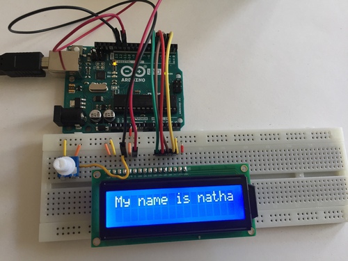
This week, I made a python interface using TKinter that could take user input and print it to an LCD display.
PySerial
I worked on using Python scripts to interface with microcontrollers. I primarily worked with pySerial and Tkinter.
PySerial allows you to establish serial communication with the board via the port it uses to connect to the computer.
If pySerial is not already downloaded you can install it by entering the following into the command line:
pip3 install pyserial
import serial
to the top of the .py file. Serial communcation with a port can then be established by writing
s=serial.Serial('/dev/cu.usbmodem####', 9600)
In which the first parameter names the port, and the second establishes the baud rate. After initializing serial communication with the board, I programmed an interface which sends strings to the Arduino. The primary command that I used was
s.write(str.encode('Ready...'))
s being my variable that represents the serial port of the arduino, s.write sends the port a string, which I encode into 1s and 0s using str.encode.
After establishing Serial communication, I was able to quickloy send some text to the screen using input entered in IDLE

TKinter
TKinter is an easy to use interface programming package for python, which comes preinstalled with python.
I got the hang of it by looking for a TKinter tutorial. I went with this one:.
I was able to create a box with a few widgets quickly. Here was my first practice, which changed the text after Welcome to: to whatever I added in the text box.


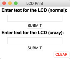
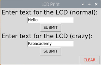
I ran into issues when I tried to work with additional widgets imported from tkinter.tkk, so I decided to just work with the standard Tkinter Widgets. This was the final interface I created, which would take text in the first entry to print normally, and in the second entry to print scrolling and on both lines of the display at once.
The code for TKinter looks like this:
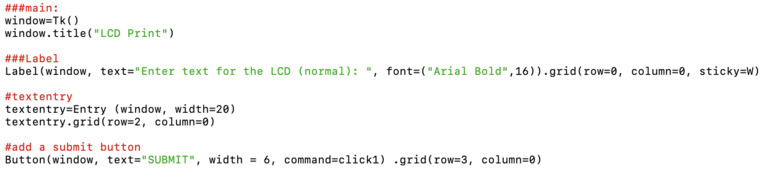
At first I establish a window, then can create widgets within that window by listing it as a parameter. See in the button where I name a command for it? Those commands can be written as functions within the same script.
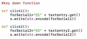
These are the commands I wrote for each button. I had the code add @1 or @2 to the beginning of each string, so that text from the different entry boxes could be interpreted differently.
from tkinter import *
import serial
import time


s=serial.Serial('/dev/cu.usbmodem146301', 9600)
time.sleep(2)
s.write(str.encode('Ready...'))


#key down function

def click1():
    forSerial1="@1" + textentry.get()
    s.write(str.encode(forSerial1))

def click2():
    forSerial2="@2" + textentry2.get()
    s.write(str.encode(forSerial2))

def e1_delete():
    e1.delete(first=0,last=22)

def click3():
    s.write(str.encode("@C"))
    textentry.delete(first=0,last=20)
    textentry2.delete(first=0,last=20)


###main:
window=Tk()
window.title("LCD Print")

###Label
Label(window, text="Enter text for the LCD (normal): ", font=("Arial Bold",16)).grid(row=0, column=0, sticky=W)

#textentry
textentry=Entry (window, width=20)
textentry.grid(row=2, column=0)

#add a submit button
Button(window, text="SUBMIT", width = 6, command=click1) .grid(row=3, column=0)

#new label
Label(window, text="Enter text for the LCD (crazy): ",font=("Arial Bold",16)).grid(row=4, column=0, sticky=W)

#textentry2
textentry2=Entry (window, width=20)
textentry2.grid(row=5, column=0)

#add a submit button
Button(window, text="SUBMIT", width = 6, command=click2) .grid(row=6, column=0)

#add a clear button
Button(window, text="CLEAR",fg="red", width = 6, command=click3) .grid(row=7, column=0, sticky=E)
Interpreting Serial Communcation in Arduino
In the Arduino code, begin Serial communcation at the same baud rate as listed in the python program by entering
Serial.begin (9600);
In the setup of the Arduino code. For my program, I was interpreting strings being sent from the python program to the arduino so that they could be printed on an LCD screen. I had the LCD connected as the pins are described in the Liquid Crystal example sketch in arduino. All the flexibility comes into the program from how the Serial input is interpreted!
It is important to understand how the methods for collecting Serial information in Arduino work. At first, I tried to use the following:
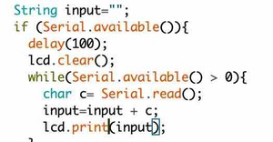
And it displayed like this:
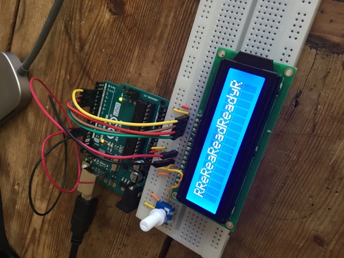
I had thought it would save each character in the string one at a time. Instead, I ended up using:
input=Serial.readString();
I added additional code, to interpret the beginning of each string to catch those address markers that I added, then print it accordingly, after also removing the address.
#include <LiquidCrystal.h>


LiquidCrystal lcd(12, 11, 5, 4, 3, 2);

void setup() {
Serial.begin (9600);
lcd.begin(16,2);
lcd.print("start");
}

void loop() {

  //addresses
  String line1="@1";
  String line2="@2";
  String clearLCD="@C";


  //Collect serial information in a string
  String input="";
  if (Serial.available()){
    input=Serial.readString();
    delay(100);


    //if string begins with 1@ print on line 1
    if (input.startsWith(line1)){
      lcd.clear();
      input.remove(0, 2);
      lcd.print(input);
    }


    //if string begins with 2@ print on line two
     if (input.startsWith(line2)){
      lcd.clear();
      input.remove(0, 2);
      lcd.print(input);
      lcd.setCursor(0, 1);
      lcd.print(input);

      for (int positionCounter = 0; positionCounter < 13; positionCounter++) {
    // scroll one position left:
    lcd.scrollDisplayLeft();
    // wait a bit:
    delay(150);
  }

  // scroll 29 positions (string length + display length) to the right
  // to move it offscreen right:
  for (int positionCounter = 0; positionCounter < 29; positionCounter++) {
    // scroll one position right:
    lcd.scrollDisplayRight();
    // wait a bit:
    delay(150);
  }

  // scroll 16 positions (display length + string length) to the left
  // to move it back to center:
  for (int positionCounter = 0; positionCounter < 16; positionCounter++) {
    // scroll one position left:
    lcd.scrollDisplayLeft();
    // wait a bit:
    delay(150);
  }

  // delay at the end of the full loop:
  delay(1000);
    }

  //clear the LCD
    if (input.startsWith(clearLCD)){
      lcd.clear();
      lcd.print("Ready...");
    }
  }


}
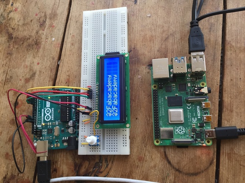
Raspberry Pi
I bought a raspberry pi that I had not yet used, so I wanted to try to run this program on it as I plan to use a raspberry Pi to communicate with several microcontrollers in my final project.
I had recently purchased a raspberry pi, so I decided to try to get this set up first, as it would likely be central to any Node-Red setup I created. From an initial search, it looked like i would need equipment I didn’t have-external keyboard, mouse, monitor etc.
I found out this is called a ‘headless’ set up. I looked for a tutorial on how to do this, and went with this one. My raspberry Pi came with an SD card preloaded with the OS, so I was able to skip the part about downloading and flashing Raspbian. I created the SSH file and wpa_supplicant.conf files in the boot drive on the SD card from my macbook, ejected the card, and plugged it into the Raspberry Pi. I then ran the following commands from Terminal:
ssh-keygen -R raspberrypi.local
ssh pi@raspberrypi.local
I wanted to control the pi from a remote desktop before doing too much in terminal, so I looked up how to do this and found it was easy to do with Microsoft Remote Desktop.
I had to install a remote Desktop server on the Pi, so I looked up how to do that and followed these instructions. All it took was running the commands
sudo apt update
sudo apt-get install raspberrypi-ui-mods xinit xserver-xorg
After that, I had to get the IP address from my raspberry Pi, which I got from typing Ifconfig in the command line. I then entered that in Microsoft remote desktop. It connected to the device. It asked me for the Username and Password, and I was in!
First I updated the Raspberry Pi
sudo apt-get update && sudo apt-get upgrade
Then I downloaded the Arduino IDE with
sudo apt-get install arduino
Python was already on the raspberry Pi. As I was controlling it from my Desktop, I was able to copy and paste the Arduino sketch and python program onto their respective applications in the Raspberry Pi, and could run it from there. The Arduino IDE did not recognize the String.remove() method, so I likely just have to update the libraries and will follow up with this later.
Arduino CLI
I wanted to create a python program that could write/compile/upload arduino sketches for the boards I would make, so that what appeared on the OLED and e-ink screens I used could vary a lot- text, animations, slideshows, individual images, charts, etc.
After doing some research, it seemed that doing this through the Arduino command line interface might be easy, as this way I could easily integrate with the libraries for devices that are already in the Arduino IDE. Additionally, you can compile in a single line, which will be very useful for the interface I want to make:
arduino-cli compile -b arduino:avr:uno /home/user/Arduino/MySketch
arduino-cli upload -b arduino:avr:uno -p /dev/cu.usbmodem...
arduino-cli compile --upload
-
Navigate to the sketch folder youy want to use in terminal, use the command $ arduino-cli boards list. This will produce the following readout:
-
From here, copy the /dev/cu. address of the port to which the board you want to program is attached
-
Enter
arduino-cli board attach serial:///dev/cu.....
- After the CLI is attached to the correct board and within the sketch folder, simply run
arduino-cli compile --upload
Maybe I can write a python program that automates this process with Python’s subprocess module and will update this page. The idea is that I will have processes that make this easy to do in an interface on the raspberry Pi, so that I can quickly change what is displayed on any connected display.
Using a Board I Made
As I had only been able to do this assignment with arduino originally as I worked on it during Lockdown, I came back to iot to recreate it with a board that I had made. I used my final project board + E-Ink display.
I simply modified the Tkinter interface to have a single line of text input, and adjusted the arduino program to write to E-Ink instead of LCD, by changing the setup to begin Serial communication with the display and prepare the font. I also had to include the E-ink libraries at the top of the sketch and list the pin connections to the ESP32. The modified files can be found below as attachments.
Here is a video of the interface working with my board and E-ink display:
Group Assignment
The link to this week’s group assignment can be found here. For this week, we each decided to work on building interfaces with different tools. I used Python and Tkinter, Tessel used processing, Hyejin used Node-Red, and Harm used scratch. After seeing all of the other tools, I though that node-red seemed very useful and like a tool that I would definitely want to learn. Aside from that, I was glad I used T-Kinter! I liked building my own project with python and Tkinter as it seemed like a more versatile skillset than processing, as I could use those interfaces not only for IoT and embedded systems. That being said, I would still like to become more familiar with processing as it seems like a great compliment to Arduino. As Harm demonstrated, scratch no longer seems to be useful.
Summary
I really enjoyed using python and tkinter this week. Tkinter was surprisingly simple, I hope to be able to use it to automate more complex operations in the future. I liked doing more programming this week, as it helped bring back my knowledge of coding from undergraduate classes. I see how having a good knowledge of programming could be a powerful asset to FabAcademy.