12. Output devices
NodeMCU ESP8266 with Waveshare E-Ink
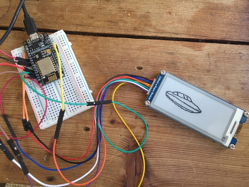
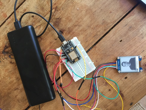
For this week, I wanted to try using the ESP8266 with a waveshare E-Ink display, as this will be a similar setup to what I am envisioning for my final project. Henk ordered me two small e-ink displays, one 1.54 inch and another 2.9inch, and I wanted to experiment with them. I wanted to use the ESP8266 because I want to try OTA programming using WiFi. So my order of operations will be:
- Get the waveshare displays running on the ESP8266
- Customize the display
- Attempt OTA programming of the ESP8266 while it is connected to the Waveshare display and change the animation
- Design and build a board with the ESP32 for these displays
Connecting display to NodeMCU
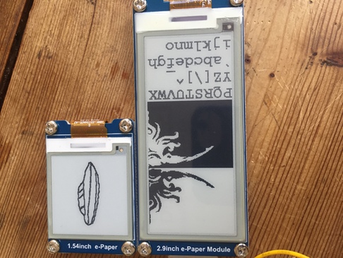
This was unnecessarily difficult and took up way too much time. A large part of this was due to the fact that the 1.54 inch e-paper display that Henk ordered was not working simply because I needed to disconnect and reconnect the ribbon cable attached to the driver—it must have been connected incorrectly. So a lot of troubleshooting on the programming/electronics side for nothing!
When I finally did try connecting the 2.9inch display and realizing the 1.54 inch display itself had been the problem, I then ran into further issues, as the board was very inconsistent in responding to programming and I thought I might be having issues with the NodeMCU. It turns out this was a good issue to have before designing the board, as I learned that the problem was that I could not have the display connected to any of the board’s UART pins while programming it.
First, I looked for Waveshare E-ink and ESP8266 setup examples online, which all referenced the GxEPD libraries. The arduino libraries designed for the Waveshare displays are the GxEPD and GxEPD2 libraries, which can be found here on github or in the Arduino library manager.
The example sketches from these libraries work by having a long list of the different waveshare e-ink displays as instances of the display class, all commented out at the beginning. You can uncomment the display you are working with for the code to work. Additionally, they offer a list of suggestions for connecting to different development boards at the beginning. For the ESP8266, they suggest:
// mapping suggestion from Waveshare SPI e-Paper to generic ESP8266
// BUSY -> GPIO4, RST -> GPIO2, DC -> GPIO0, CS -> GPIO15, CLK -> GPIO14, DIN -> GPIO13, GND -> GND, 3.3V -> 3.3V
I followed this suggestion for connection, uncommented the 1.54” display I was working with, and attempted to compile and upload to the NodeMCU. I kept running into the error that the board did not exist or was not connected. This was frustrating, as I would see a light blink on the board when I tried to upload, so I knew some communication was happening. I tried to upload Blink, and this didn’t work either. I then looked up the issue in a forum, and some people suggested that I go into the Board Manager and install an earlier version of the NodeMCU driver instead of the latest one. This also didn’t work.
I found out about the esptool.py command line interface, attempted to use this to delete flash on the board, as I thought maybe working outside of Arduino would offer some help. I downloaded the software using
pip3 install esptool
and attempted to use delete flash with
esptool.py erase_flash
which automatically scans for esp boards on each port and erases the flash memory when it finds one. The port for the ESP, named /cu.SLAB_USBtoUART would give the following output when the software checked on it:
/dev/cu.SLAB_USBtoUART failed to connect: [Errno 16] could not open port /dev/cu.SLAB_USBtoUART: [Errno 16] Resource busy: '/dev/cu.SLAB_USBtoUART'
I finally thought to disconnect the display, something I had been resisting as it required 8 pin connections so was a bit of a hassle to disconnect and reconnect. When I did this, I ran erase-flash again and it worked!
I went back to Arduino, compiled the example sketch, and uploaded it, and this also worked!
I plugged the display in and…nothing. I tried resetting the ESP, disconnecting and reconnecting again to double check my connections, still nothing. I moved it to a breadboard so the connections could stay in place if I picked up the board. I still was having no luck, so i switched to the 2.9 inch display and an image instantly appeared!
Good news. I changed the example to work for the 2.9 inch display, and again had trouble with the board with the same upload error. I disconnected the display, and it was able to upload. I was very excited to have the display finally working, but I needed to figure out why I couldn’t have the board connected and upload at the same time, as this would be a big obstacle in my final project if this was something I could not fix.
I looked up the issue, and saw a discussion of it happening with Arduinos when the Tx/Rx pins are used in a sketch, and it recommended to avoid using them. I tried plugging in the pins on the ESP one at a time until the sketch failed, to try to get a sense of which one prevented upload. I figured out it was D8, which was connected to the clock pin on the display. When I looked at the ESP8266 data, this made perfect sense. This was one of the UART communication pins. Of course, as i was connected through a UART converter, I should avoid these lines.
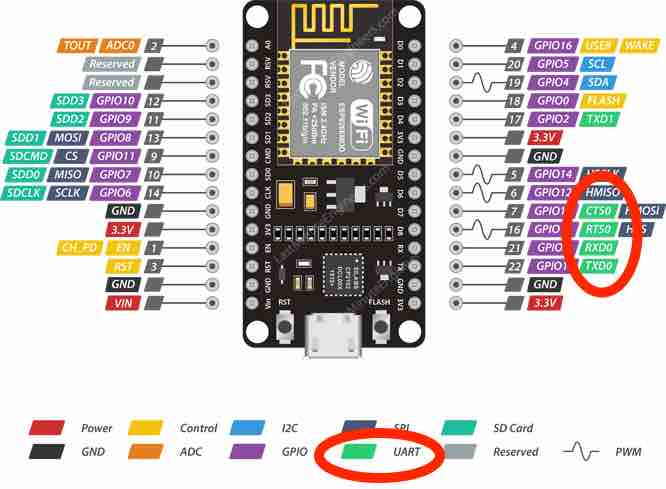
I connected to the clock pin on the other side of the board, which was not listed as a UART pin, and it solved the problem. I was able to upload and be connected to the display at once. Huge relief, and many hours gone, but at least I could be grateful I did not design a board with those same connections as listed in the example.
After this realization, I started to do some general web searches for connecting the e-ink displays to the ESP32, as this was the microcontroller I wanted to design a board for with the waveshare display. I found that waveshare already makes an ESP32 driver for the e-ink displays, which is essentially what I would be making. However, in the pictures it showed the ribbon cable connected to the driver, and I got to thinking that I had not checked if this was ok on the 1.54” display. I disconnected and reconnected the cable, and this display could now run with the upload sketch too! I felt stupid that it was such a simple fix, but I was glad to now have both displays working.
Customize the Display
On the GitHub page for the display libraries, he describes how the GxEPD libraries are a subclass of the Adafruit GFX libraries, so I look into the Adafruit documentation for information on ways I can print to the screen.
I tried using the GxEPD example code, but found customizing this difficult, as each part of the example display was called as its own method, and the code contains different commands for different boards and screen sizes. I instead looked around for a post going over how to start from nothing and simply print text or a single image to the screen. I found this website.
void setup() {
// setup the display
display.init();
// colours are good.
display.fillScreen(GxEPD_WHITE);
display.setTextColor(GxEPD_BLACK);
// load a font - in the library
display.setFont(&FreeMonoBold9pt7b);
// let the strings begin
display.setCursor(0, 0);
display.println();
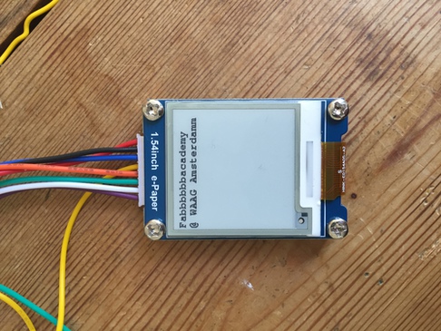
display.println("Hello. My name is Inigo Montoya. You killed my father. Prepare to die." );
display.println();
display.println("This is another line!" );
display.update();
}
This is the example code for printing text to a waveshare e-ink display from the website. It did not have any calls to include or define at the top, so I tried adding only #include
#include <GxFont_GFX.h>
#include <GxEPD.h>
#include <GxGDEP015OC1/GxGDEP015OC1.h>
#include <GxIO/GxIO_SPI/GxIO_SPI.h>
#include <GxIO/GxIO.h>
#include <Fonts/FreeMonoBold9pt7b.h>
GxIO_Class io(SPI, /*CS=D8*/ SS, /*DC=D3*/ 0, /*RST=D4*/ 2); // arbitrary selection of D3(=0), D4(=2), selected for default of GxEPD_Class
GxEPD_Class display(io, /*RST=D4*/ 2, /*BUSY=D2*/ 4); // default selection of D4(=2), D2(=4)
I still do not completely understand what all of these are doing, but including them made the code work!
Now, I wanted to test getting images running on the display. The same tutorial from above also included basic code for this, which was to include a byte array:
 const unsigned char gImage_IMG_0001[] = {
    0xff, 0xff, 0xfb, 0xff, 0xff, 0xfe, 0x00, 0x08, 0x80, 0x08, 0x4a, 0x4c, 0x65, 0x2a, 0xf,
    ...
   };
Then add these lines in the program:
 display.fillScreen(GxEPD_BLACK);
 display.drawBitmap(0, 0, gImage_IMG_0001, 200, 200, GxEPD_WHITE);
 display.update();
I tried to just copy and paste one of the bitmap arrays from the example code, but this did not work and produced this:
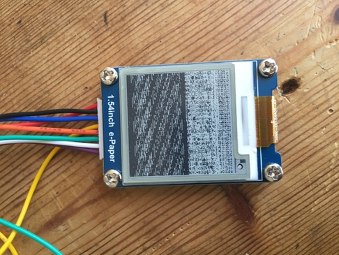
I then made my own image with photoshop, using only black and white pixels, and made it exactly the resolution of the screen, 200x200. I used several online image to c array converters, and all of them produced the same hazy display. Finally, running the file through this converter produced a code that worked.
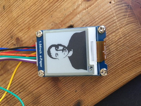
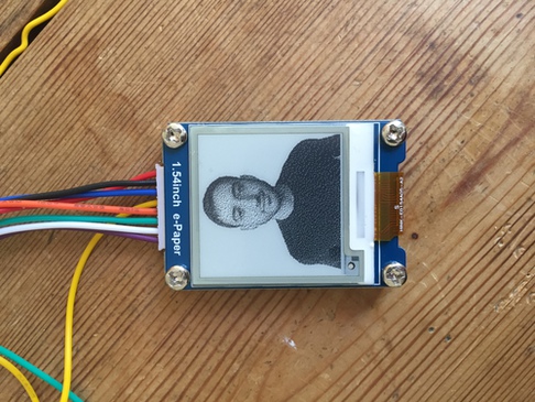
I had made this image using the threshold effect in photoshop, but knew I could get a more photo-like result, so i changed it by first choosing Image > Grayscale, then Image > Bitmap. Once you click on bitmap, it will give a menu for different ways of creating the bitmap (halftone, threshole, etc). I then ran the new bitmap I made through the same converter as above, and produced this:
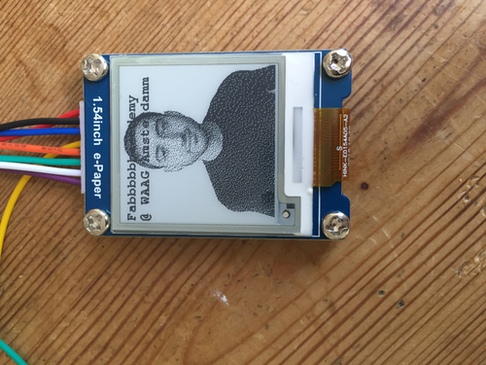
I then combined the image and text code, and also had them alternate.
OTA Programming
This ended up being the easiest part. I looked at several tutorials online for ota programming. If you have python installed, there should be an ‘Arduino OTA’ example code from the arduino File > Examples menu.
#ifndef STASSID
#define STASSID "......"
#define STAPSK  "......"
#endif
Substitute your wireless network and passcode for these two strings and upload the code to the ESP. Then, open the serial monitor. Hit reset on the ESP. The IP Address of the ESP should appear in the serial monitor if the program ran successfully. Now, when you go to Tools > Port, the IP Address should appear as an option. To put your own program on the ESP and maintain OTA programming capabilities, you simply need to add your sketch into the OTA example sketch. I copied the definitions and setup from the e-ink customization sketch, and added them into the OTA sketch, changing the text printout so I would be able to know if it successfully sent a new program. I unplugged the ESP and plugged it into a powerbank. I uploaded the new code using the OTA port and it worked!
The only problem I ran into here was inserting my own code into the OTA sketch in the wrong place. There are several loops in the setup, and I accidentally put part of my code inside of one, which prevented it from printing. This had me stuck for at least an hour and was a silly mistake.
Board Design
Please see my final project documentation for an ESP32 board designed to work with this same E-Ink display.
Summary
It was exciting to be able to display photographs, as this is closer to the kind of real world appication I will want to use in my final project. It was also satisfying because E-Ink is a bit daunting at first, especially with all the wires. Once it was wired correctly, I was surprised at how much has to be done on the software photo in order to display a photo, like converting it to a c-array.