17. Mechanical design
group assignment
 - design a machine that includes mechanism+actuation+automation
 - build the mechanical parts and operate it manually
 - document the group project and your individual contribution
We made a “simple drawing machine” which ended up being more difficult than we expected! To make the project a bit more exciting, Florent from AgriLab worked with us remotely, and was able to draw using a remote control that worked over the internet.
The documentation for our group work can be found here.
Tessel and I both worked primarily on the casing for this project. We first made the cardboard design that we pulled from the MIT lab’s guide, and then designed an acrylic case to stabilize it. Both of these took way longer than we expected. My part of the documentation is quoted here:
Making the casing more sturdy
For the design, we wanted to make a shell to encase the cardboard structure so that it would be sturdier and look nicer. There was a lot of scrap plexiglass laying around from Rutger’s work at the start of quarantine. The design involved 3 main parts.
- An outside casing for the stepper motor assembly attached to the base
- An outside casing for the higher stepper motor assembly, with additional components to hold the Z-Axis motor and its gear system
- Supports for a bridge which would balance the Upper assembly as it moved.
We made the entire design in a few hours over the weekend, but it took foreverrrr to fabricate. This was partly because Nathan decided to make the design press fit, and probably should have abandoned that idea and used glue much earlier.
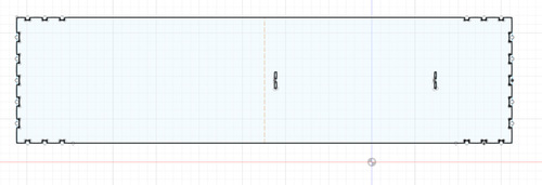
This was time also time consuming because using the laser cutter is so much more frustrating than I remembered. Many times, the files simply would not open, or the entire computer would shut off. The laser cutter requires .ai CS2 files. I was working in fusion, so I would have to save as a dxf, open in AI, save again as a legacy format, then bring to the machine. I often had to repeat this process a few times to get a file to work. The settings I used for cutting 3mm yellow plexi were Speed: 20, Power: 100. The main shell design involved a 3 part press fit kit, a large rectangular base, then a pair of triangles and a rectangle that fit together at the ends to make the end of the box.
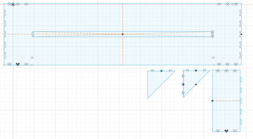
We used finger joints, and added circles to the inside corners of the joints to prevent cracking.
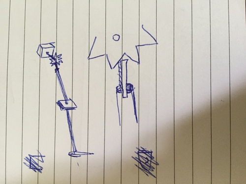
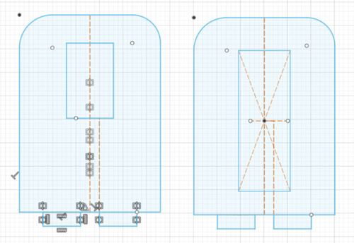
 We drew this rough sketch of the Z axis support system. It involved a gear, pen holder, and fulcrum.
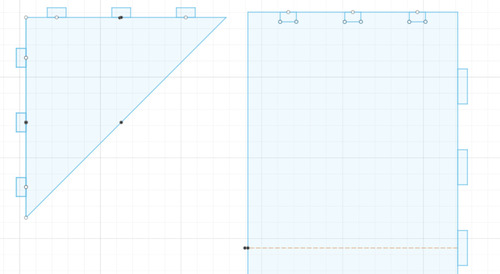
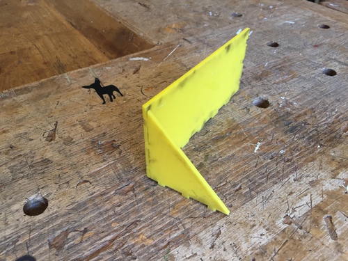
 Here is a design for the fulcrum and an additional guide for the stick, with finger joints that fit into the shell on the outside of the box.
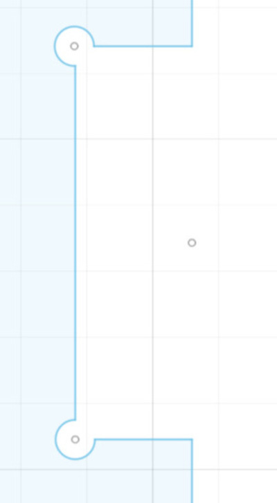
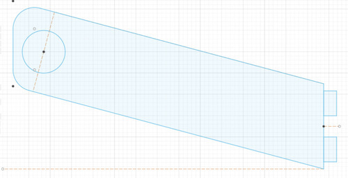
 Here is an initial bridge support we made. The idea was that it would fit into a base for the drawing machine, then hold a wooden stick that the box could roll over as it moved. We did not end up using this design.
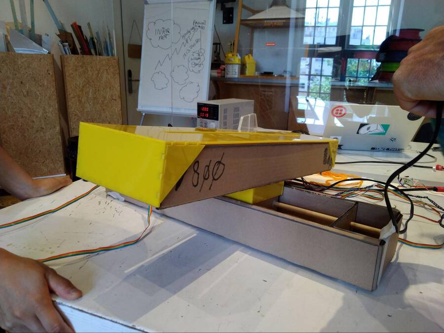
 The shell joined together:
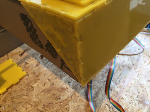
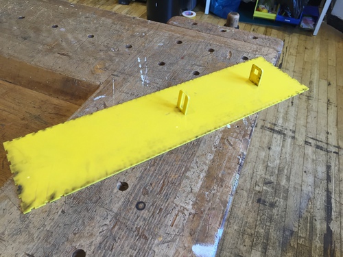
 The top shell, with fulcrum and Z axis guide:
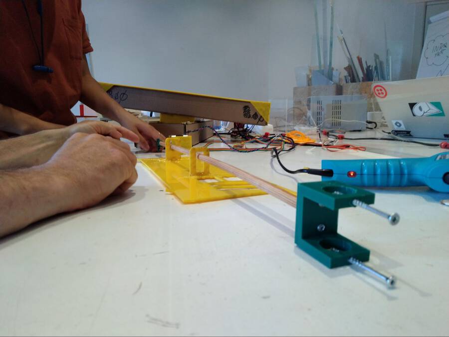
Building a supporting bridge
We had thought a lot about making the supporting bridge. We considered several fancy designs. But by the time we came to making the bridge, time was running out. So Hyejin and Tessel did a really quick job. We decided to make four boxes with holes in the side. A stick would be run through the holes. The arm can then lean on the supporting stick. These bridge boxes would be placed on either side of the arm. Hyejin made a design in Fusion360 really fast. It consisted of three parts. Two standing faces without holes and two with holes for the stick. Bottom and top of the box are a single square. We decided not to use press fit. Time was running out! Instead we would use the glue gun Harm had found earlier in the day and was happily glueing anything that was lying around loose. We laser cutted the parts and Hyejin, Harm and Tessel glued them together. It all was super sturdy. Or at least sturdy enough. But then minutes before the Lab was closing Harm send the arm too far and it pulled the bridge down with it. We have only tomorrow morning to fox everything. But we will make it :)
What I learned
I learned that, like most things in fabacademy, getting a machine to function takes way longer than expected. We began with a more ambitious idea— a walking robot dog, but after some fear that we would not be able to complete this in time, we decided to follow the guide for a simple drawing machine, and that we would add further spirals to this once it was completed. This ended up being a very good decision, as we were barely able to pull the first spiral together in time. As we had to delegate tasks, it was also hard to learn everything that I wanted to from the project. Design work took up too much time, so I was unaware of the mechanics or communication system that Harm and Florent were working on. That is the nature of group work, however, and I felt that otherwise we worked well together.
Press Fit
I think I could have also sped up my part of the design work— I could have used fewer joints in the design and it would have made it possible to fit everything together more quickly. Fine tuning the kerf was the most difficult part, as I kept adjusting by fractions of a millimieter, and it would then fit on some shapes but not another, or crack easily, etc. I think I also could have had even a more perfect fit with kerf adjustments, but once they snapped together at all I went with that sizing because of time constraints. Henk also pointed out that there were visible burn marks, so I could use lower power in the future.