3. Computer Aided design
Fusion 360 Tutorial
On Thursday, Mauro visited our class from Rome to give an all day introduction to Fusion 360. I kept up until the final hour, when I got a bit lost as he guided us through animation. I will summarize what I did pick up here:
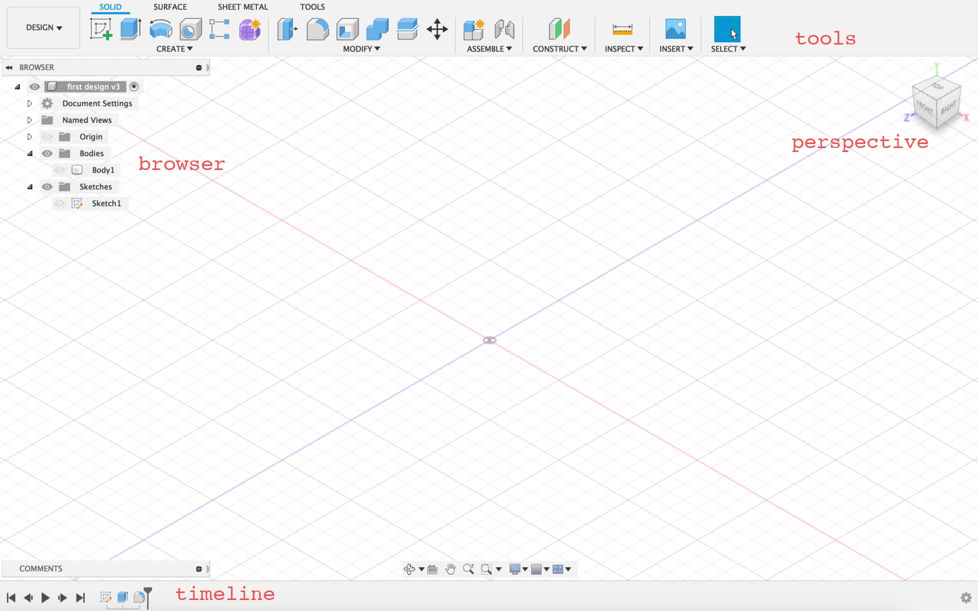
He first introduced us to the workspace, and described its componenet parts, labeled here.
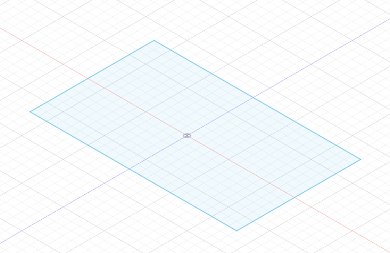
He then introduced a very basic workflow, in which we move from a sketch to a body.
We began with create sketch and drew a rectangle.
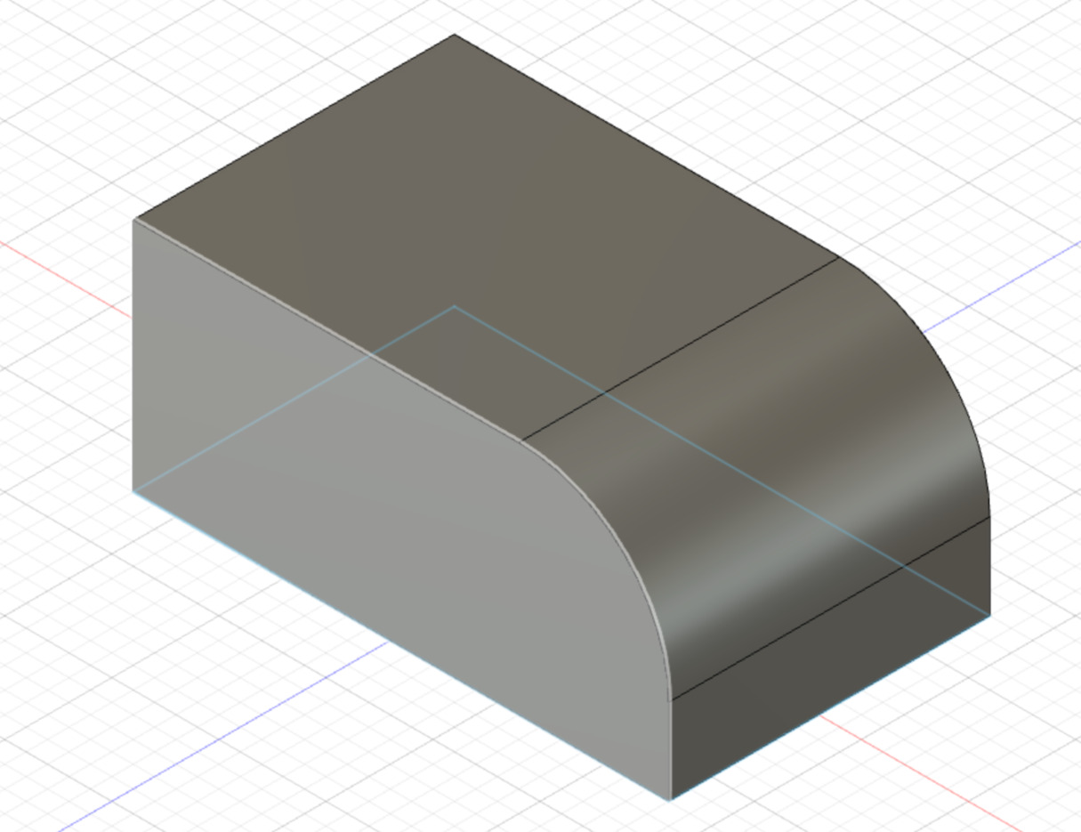
We then clicked finish sketch. Now in the solid workspace, we used the command extrude in the Create menu, and fillet in the modify menu.
Finally, he explained how each step of this process could be modified in the timeline, and altering an earlier step would apply changes through all of the later steps.

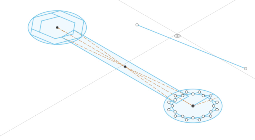
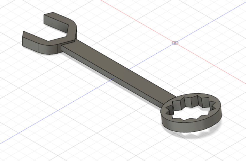
After we undertsood this workflow, our first big task was to make a wrench in fusion, starting with a sketch.
During this process, we learned about constraints by using the equal constrain to make the circles on each end of the rectangle the same size. We additionally used an offset to shape the hexagonal end of the wrench, placing one hexagon inside of another. We also used the command create circle pattern to create the circle of triangles on the closed end of the wrench.
We extruded each part of the sketch separately, so that we could extrude the closed end from a different plane as the other parts, as it sits at a slight angle from the rest of the wrench. Finally, we joined all of these pieces and had our wrench.
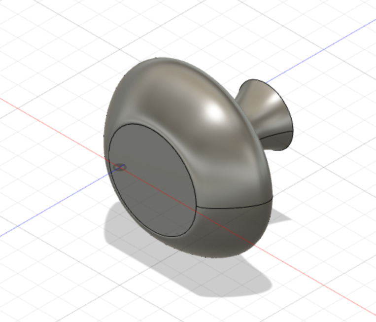
We then went through a few more, less time consuming exercises. We used revolve and shell to make a vase.
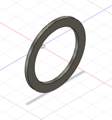
We also revolved a shape around a distant axis to make a wheel.
We used loft to make a body from sketches on multiple different planes.
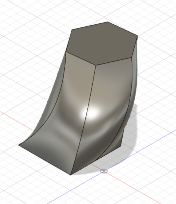
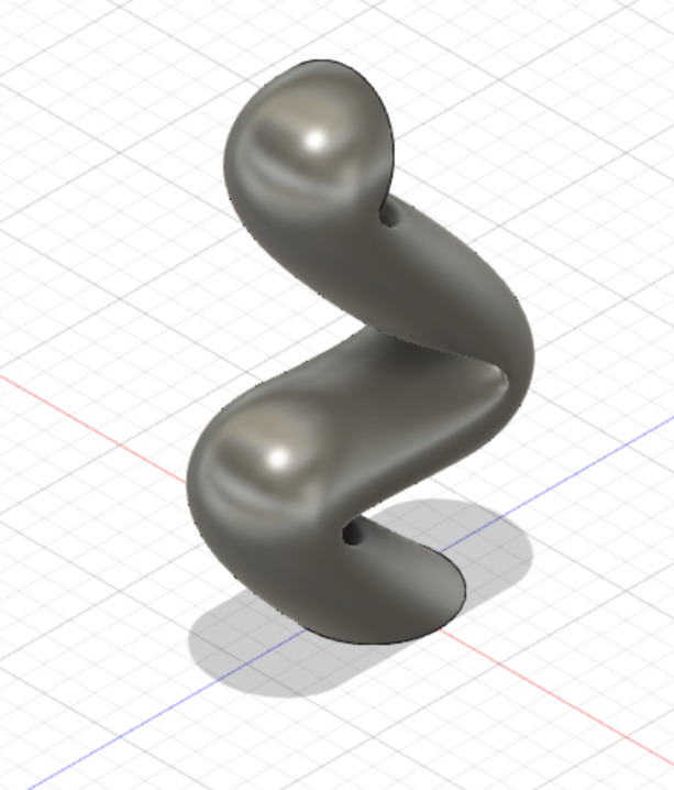
We used sweep to create a shape from having a sketch follow a spline.
Then we moved on from solids to learn about surfaces, a kind of body without thickness.
We learned about surfaces through the extended task of making one “arm” of a pair of eyeglasses.
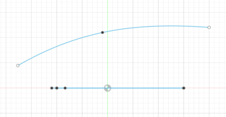
First, we sketched the shape of the arm.
Then, on the plane perpendicular to the arm, we drew an arc. The line underneath the arc is the glasses arm drawn from the side.
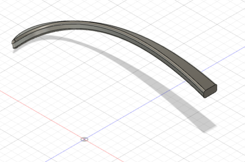
We then extruded both the arm and the arc, and used modify > trim to cut away the excess surface, leaving us with a curved glasses arm where the two extrusions met. We then extruded and filleted this shape to make the final product.
After this, we worked on animating objects using joints. I got a bit lost here in class… but I animated the model I made for this week, so I’ll go over how that’s done later on this page.
Screen Recording
Before I got started this week, I wanted to find which screen recording software would work for me, as I knew I would likely want to record something in the CAD design and would need to know how to do this for the rest of FabAcademy.
The main screen recording software we discussed on Wednesday was SimpleScreenRecorder. This wasn’t an option for me as it is Linux software and I am using Mac. A google search yielded a MacWorld article describing how Mac OS since 2018 has screen recording software built in to the screen shot toolbar, which can be accessed by hitting Cmd + Shift + 5. Clips can also be trimmed quickly by using the ‘Quick Look’ menu that pops up immediately after a screenshot is taken. I will likely do most of my editing using these tools, and if necessary will use Premiere as it is the software I am most familiar with.
I still will need to format screen recordings, so I downloaded ffmpeg through Homebrew:
brew install ffmpeg
Choosing CAD Software
I looked through the following links to gain a general understand of what CAD software is available out there, but as we had such a great Fusion tutorial and I had a hard enough time picking up on everything in that, I decided to stick with Fusion.
The Best 3D Modelling Software 2020
Top 10 Best CAD Software For All Levels
Modeling A Possible Final Project
This week, I had trouble thinking of a final project I wanted to model, so I tried to think of objects I had seen before that I wished I knew how to fabricate. I remembered that a few months ago I saw some sculptures by the artist Alex Da Corte and wanted to know how they were made. They were images sourced from cartoons that he made into 3D wall works. I am not aware of what process he used, but it looked like the kind of thing 3d fabrication could help with.
I decided to try to model something similar to one of these works in 3D software, and think about a way to incorporate movement and input/output on the way.
What I was most excited about was starting with a simple sketch, and finding a way to preserve a cartoonish look in the final product.
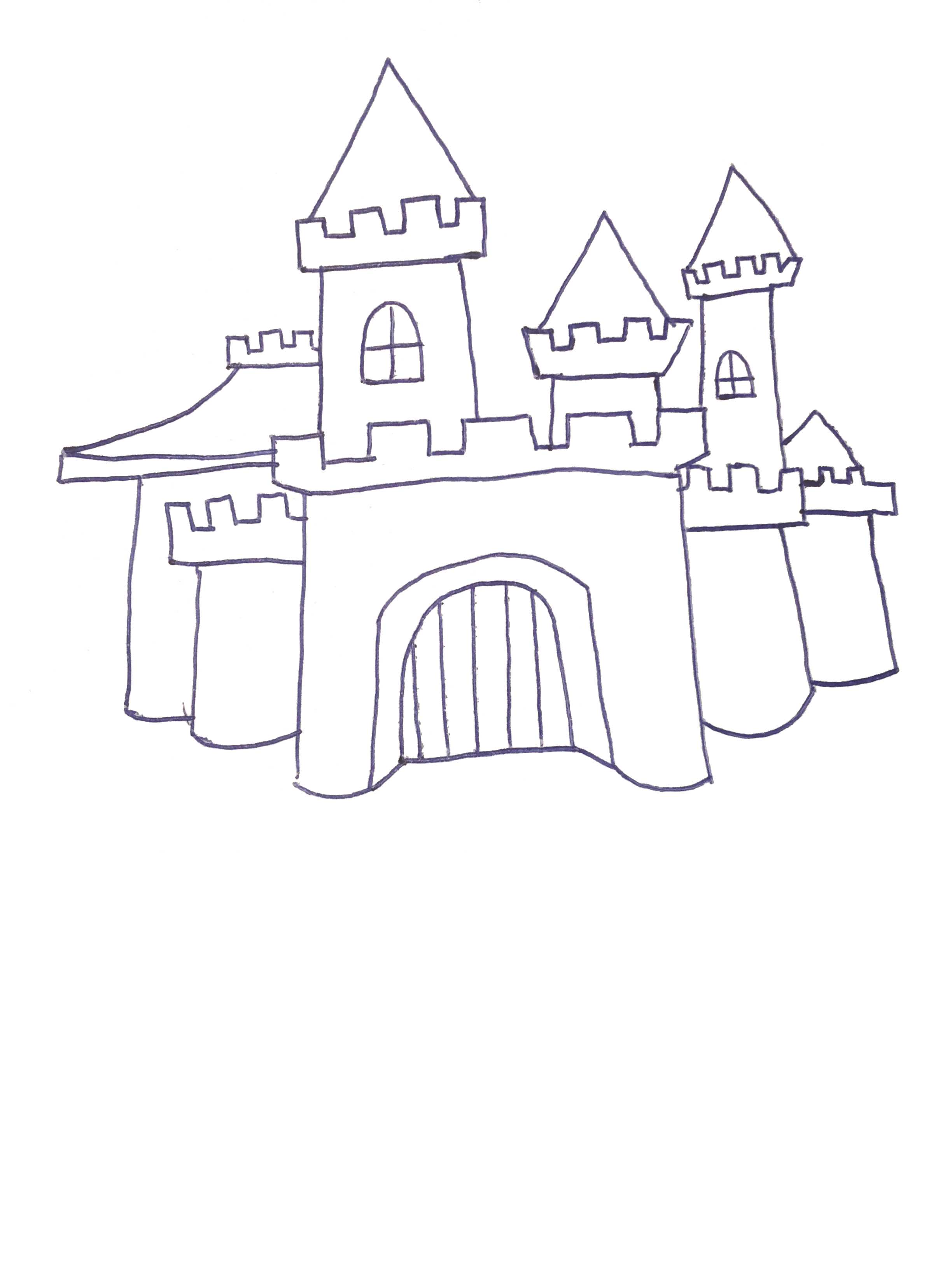
I started with a few different sketches.
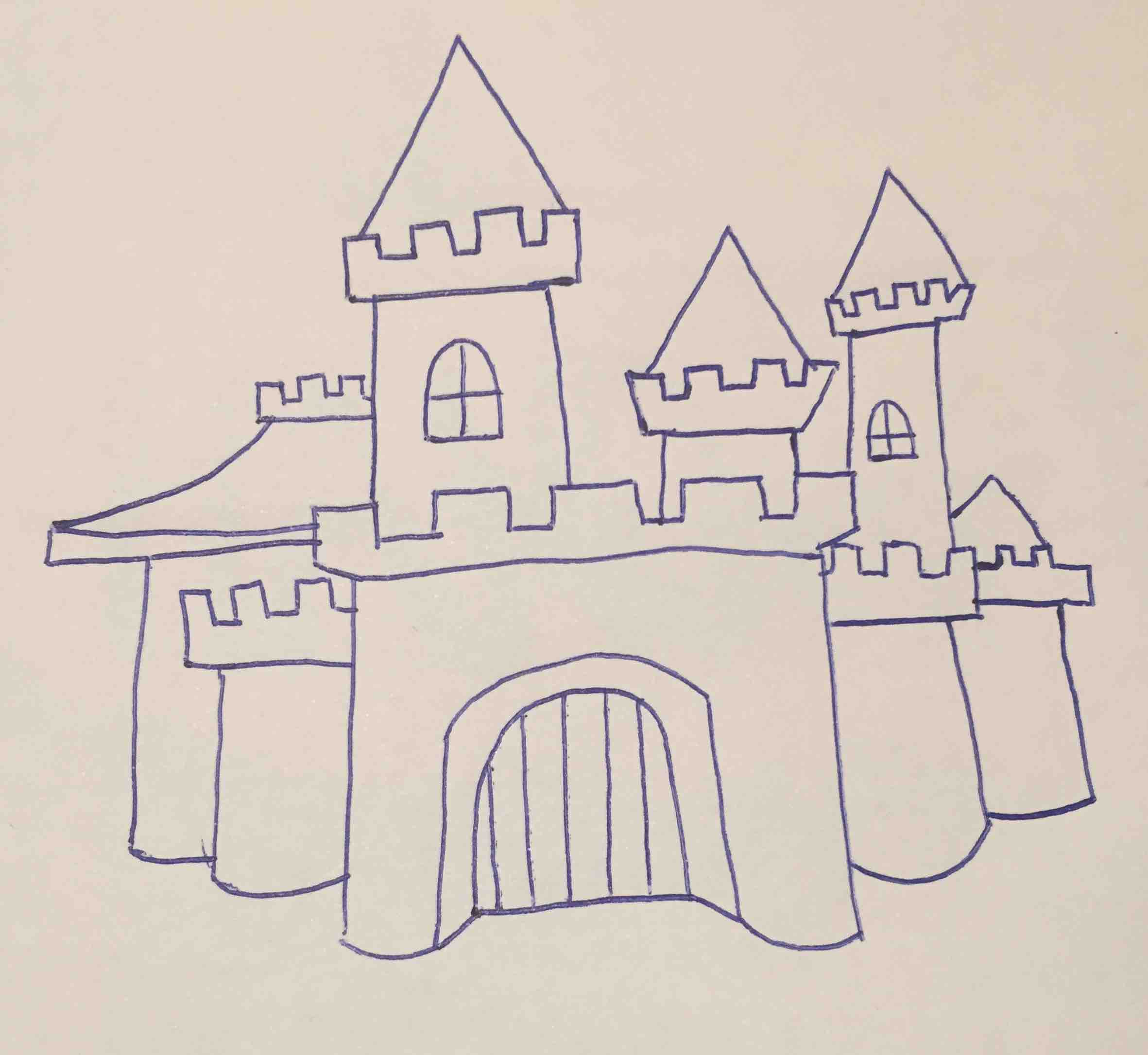
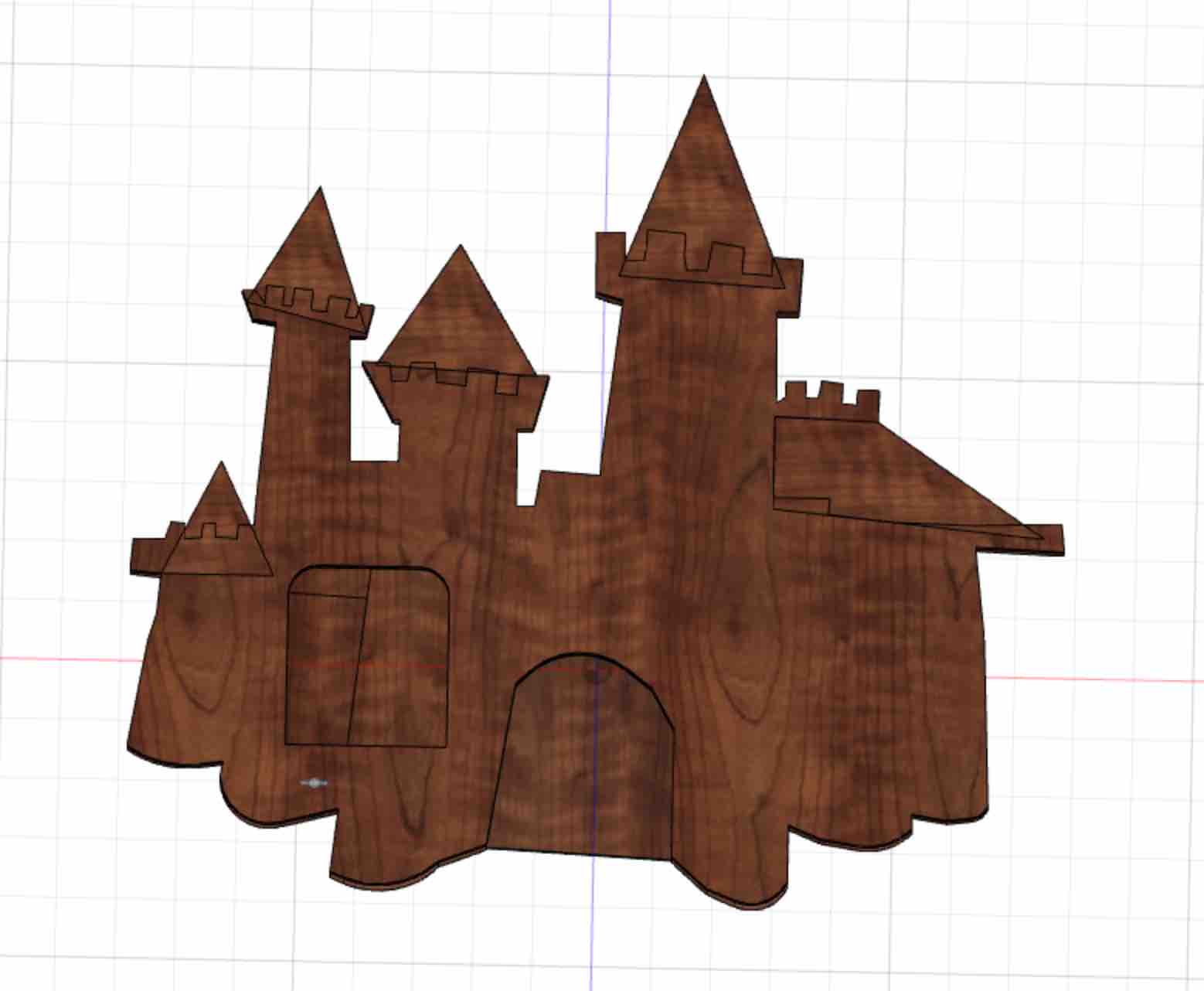
I decided to go with the castle as it would have the most dimensionality to work with.
2D
Raster
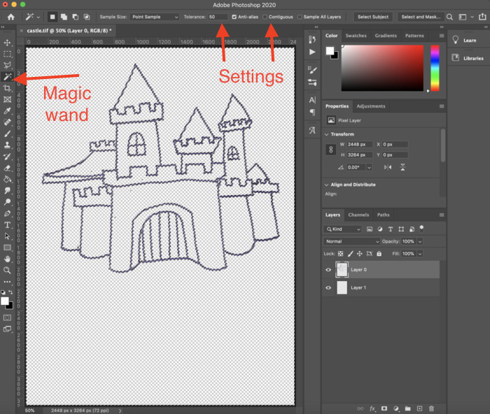
I am already quite familiar with Photoshop and use it often. I first brought the castle sketch into photoshop to prepare the file for illustrator.
I used the magic wand tool to select the entire paper background at once. This tool selects areas of the image with the same color, and the tolerance can be adjusted to determine how much variance around a certain color you want to accept. Additionally, you can check or uncheck contigueous, to determine if you the selected areas must all be touching or not.
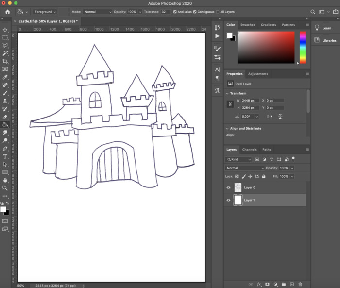
After deleting the selected paper background, I used the color fill tool to fill a layer beneath the sketch lines with white, so the sketch was now on a white background. I exported this file as a jpg so that i could bring it into illustrator.
I am less familiar with Illustrator than I am with photoshop.
At first, I thought I would try making my image a vector in Illustrator, then bringing that vector into Fusion and trying to work with it from there. Sounded easy!
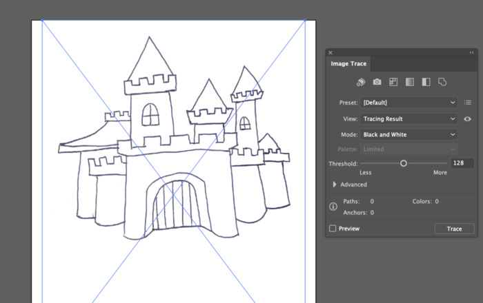
In illustrator, I used Image Trace to make the sketch into a vector. I watched a tutorial on how to use the tool first.
I dragged the JPG I had made into illustrator, then opened the Image Trace window from the menu using Window > Image Trace. This tool works by turning raster lines into vectors. In this window, you can adjust how the tool will respond to the image by adjusting the threshold, or how much contrast the lines will have, and the amount of lines and corners that the image generates.
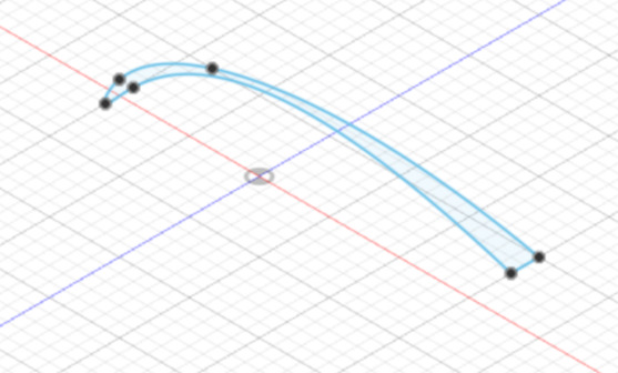
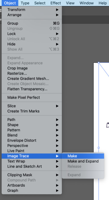
After making these adjustments, use the Menu to go to Object > Image Trace > Make/make and Expand. This will generate vectors from the lines. Here are the paths generated from my image, now with anchor points:
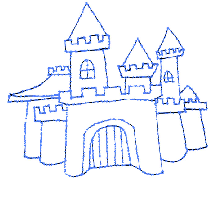
It works quickly. I saved the image as an svg then brought it into Fusion by selecting insert > Svg.
I realized this was a lot more trouble than it was worth, as the varying line thickness from the pen made the outline into shapes rather than lines.
I decided to try and trace the image in illustrator by drawing lines rather than using image trace. However, after getting started I realized this step might be unnecessary and I could try tracing it straight inside of fusion.
3D
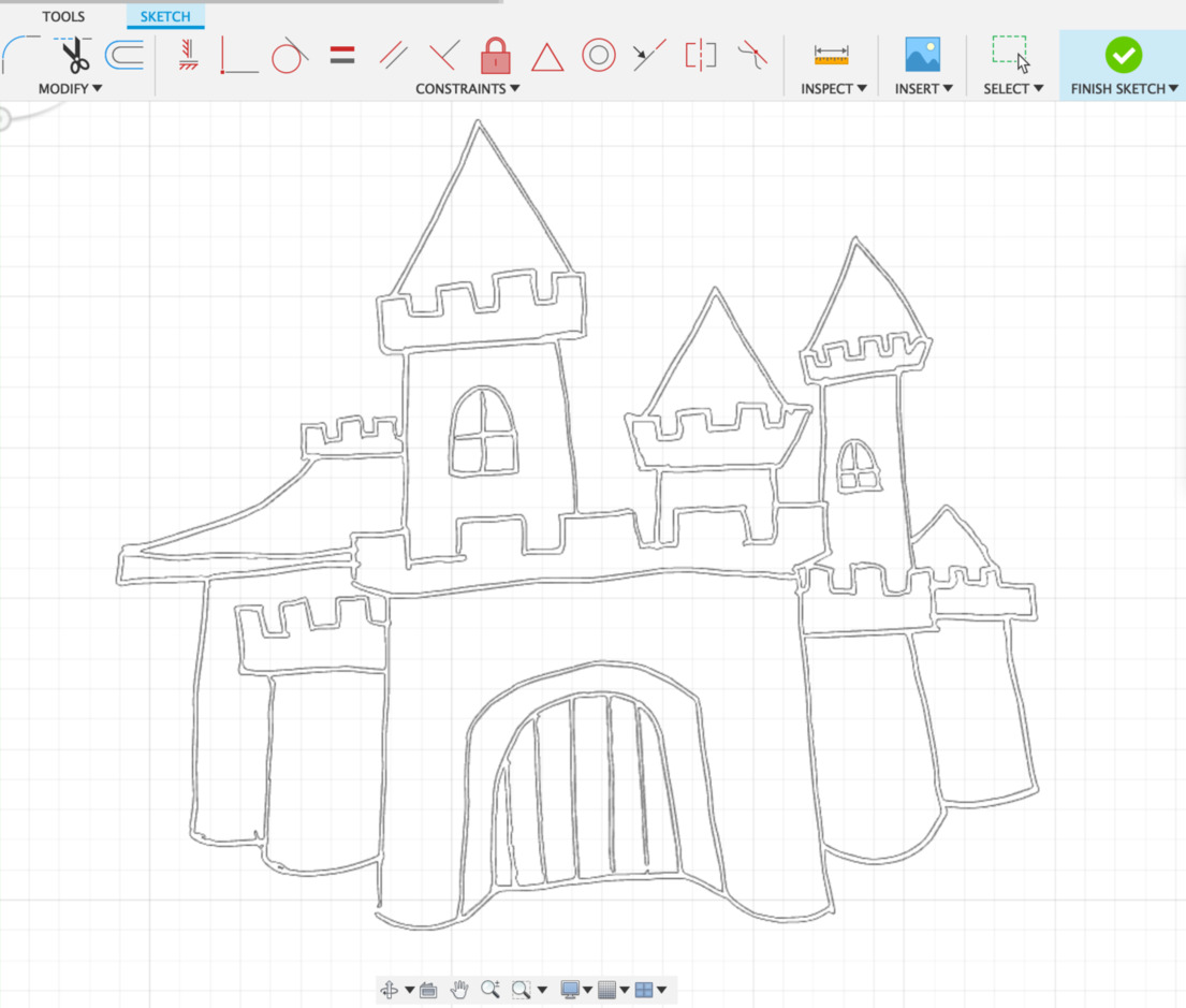
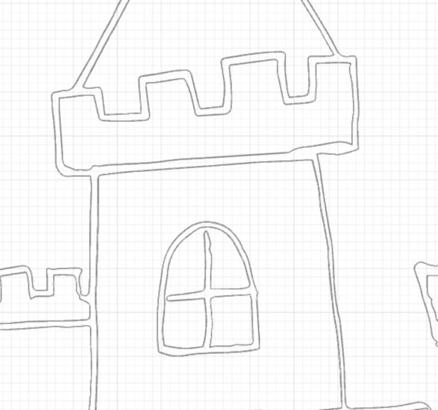
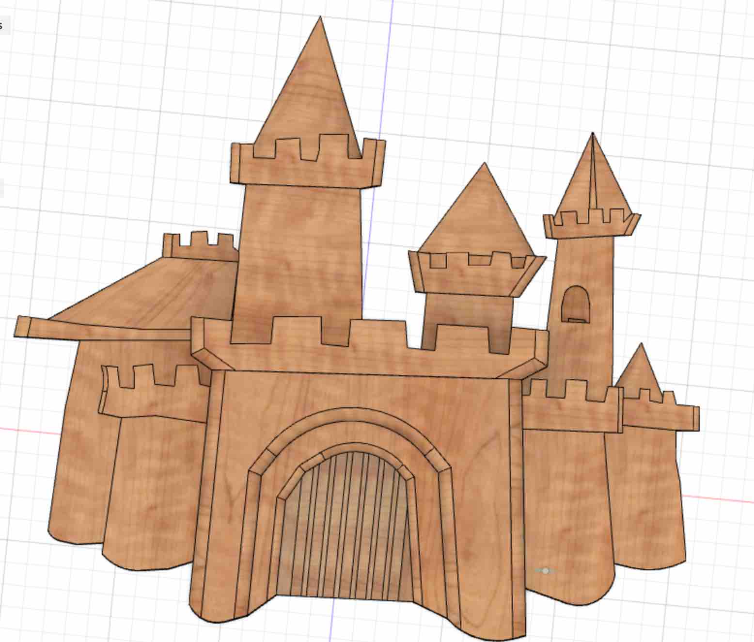
I found out you can open a jpg in Fusion as a ‘canvas,’ so I opened the image and then traced it as a sketch- this ended up being easy and seemed even quicker than illustrator.
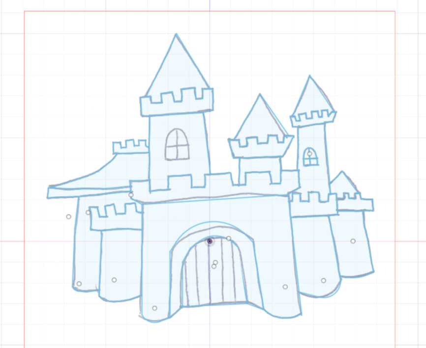
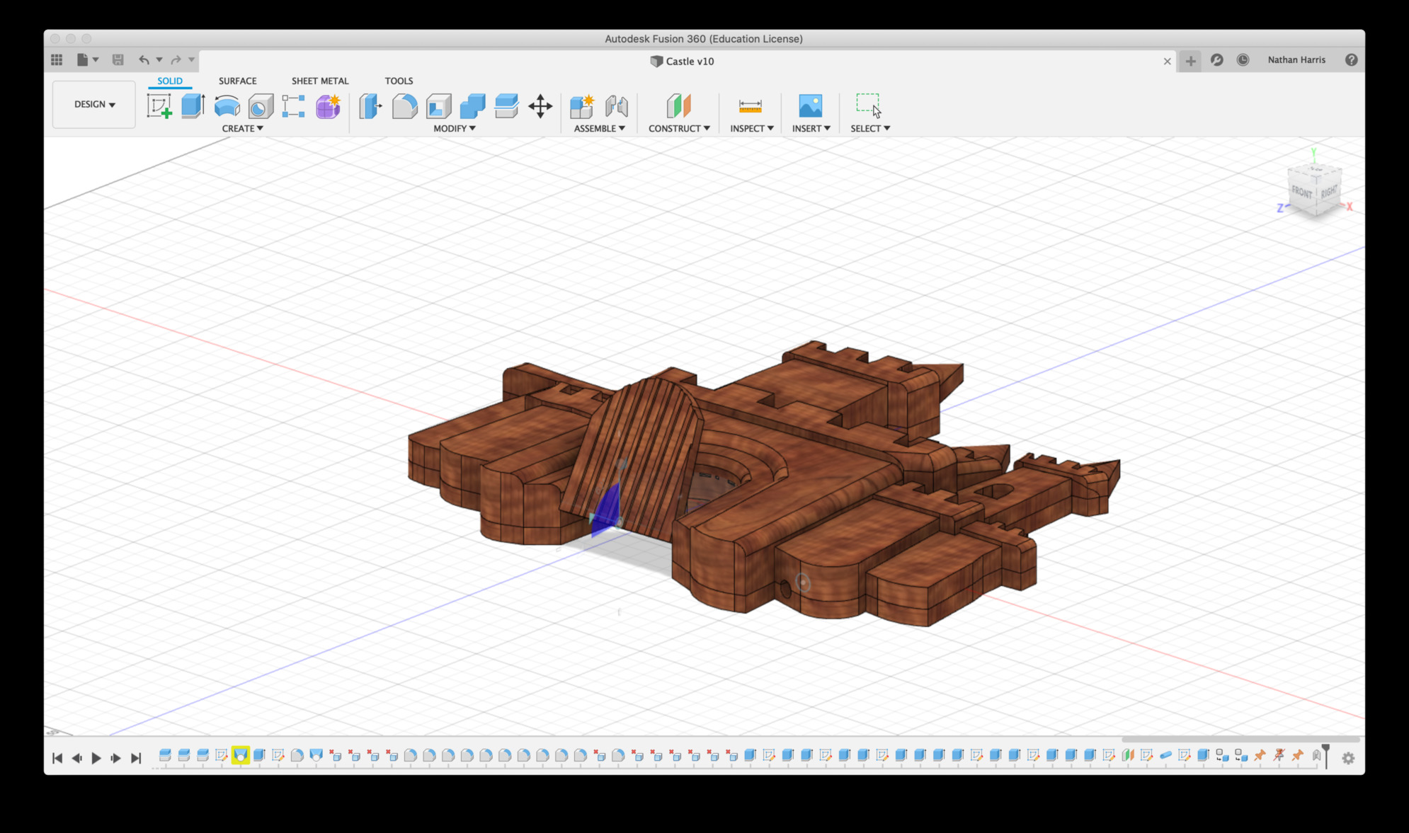
From there, I went about extruding and filleting all the sections from the sketch.
I ran into the most trouble with the cones at the tops of the towers. As they were drawn, the bottoms were not straight edges, but had the rectangular sections from the negative space of the battlements attached to them, so it caused the revolve command to malfunction
My first thought was to make new sketches that I could revolve to make cones, so I drew triangles that went below the gaps in the battlement, and tried revolving these around an axis near the center point of each tower. The cones this process made were way too wide.
My next thought was to fillet the edges of each triangle until they were so rounded that the fillets met in the middle. The issue with this was that it produced a small flat triangle near the center of each cone.
Finally, I remembered lofting from the demo. I thought that maybe I could loft an ellipse the length of each battlement to the top point of the cone, and googled to make sure this was possible.
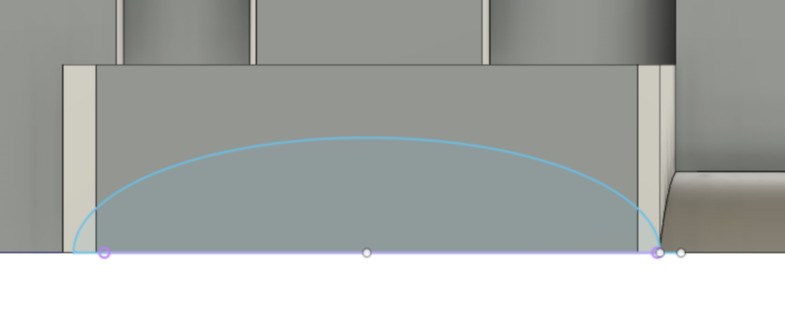
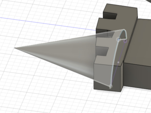
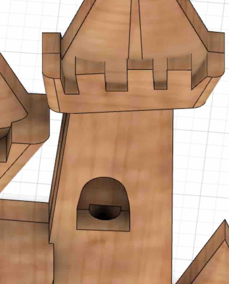
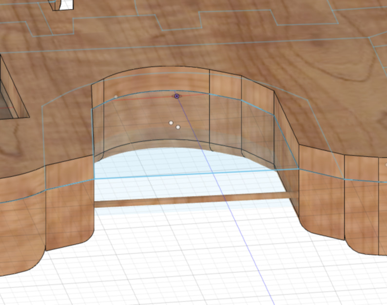
I started a new sketch on a plane at the top of the tower solid, drew an ellipse, and removed half of it so it would not extend past the flat back of the castle. I then made a loft between this half ellipse and the pointed tip of the tower in my sketch. This finally produced what I was looking for–a continuous rounded front on a shallow cone.
I repeated this same process for the other towers. For one of them, I added an additional, smaller ellipse to the base of the loft to vary how they look.
After all of the solids were done, I added an additional flat layer to the back of the entire shape.
Next, I tried to add skins to the castle in render, but when I tried to drag different materials to different bodies, I realized the bodies were grouped together strangely. I had forgotten to be careful about setting each extrude command to “new Body” so many of them had joined together.
This was a lot more difficult to fix than I thought it would be. Clicking on each body and “edit feature” was not that effective if I did not follow the order of the timeline, so I ended up going back through the timeline step by step from the beginning and making sure I made a new body with each create command.
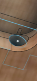
Once these were all separated, I got distracted from rendering and decided to build out some of the finer details. First, I made an inlet to store electronics on the back, and cut holes from this area to the tower window, the front gate, and the bottom of the design. My idea here is that I would have some kind of sensor in that window that signaled to open the door.
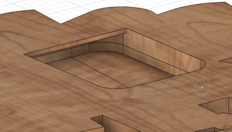
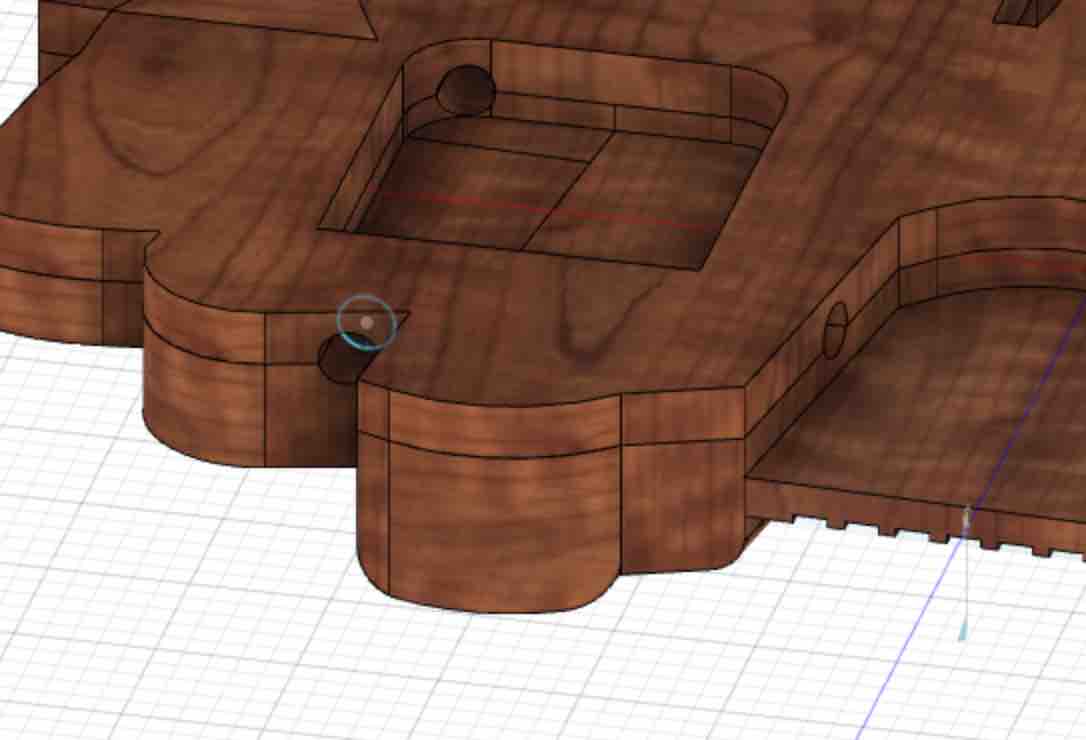
This part got a bit complicated, as I had to make sketches on several different planes and make sure they cut through the design to the point I wanted to send them to.
At one point, one of the tunnels I made cut a small notch into the back of the inlet. I had already made two extrusions from this circle, so I appreciated parametric design here, as I only had to scale the circle in the sketch to change both extrusions.
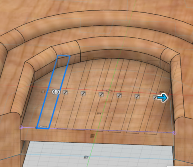
Finally, I added the door. I took the opportunity to use many of the commands that Mauro had showed us that I hadn’t used yet. First, I extruded the door from a plane offset to the original sketch. Next, I made a sketch on the surface of the door of a rectangle that I would use to add a pattern of indents to the door. i multipled it with the rectangular pattern command, finished the sketch, and made cut extrusions into the door.
Next, I offset a plane from the surface of the door to halfway through the door. Then I sketched a line on that surface through the bottom of the door. I then made that line into a pipe.
I then created a joint with the door and the pipe, so that the door would open by spinning around the pipe. I set a constraint on the door so that it would not spin all the way around, but stop at a 90 degree angle and rest in the closed position.
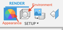
Render
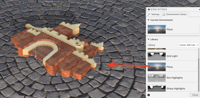
In the render environment, you can choose different materials for the surface appearance of the object created, as well as adjust background and lighting, so that it appears as if in a non-computer environment.
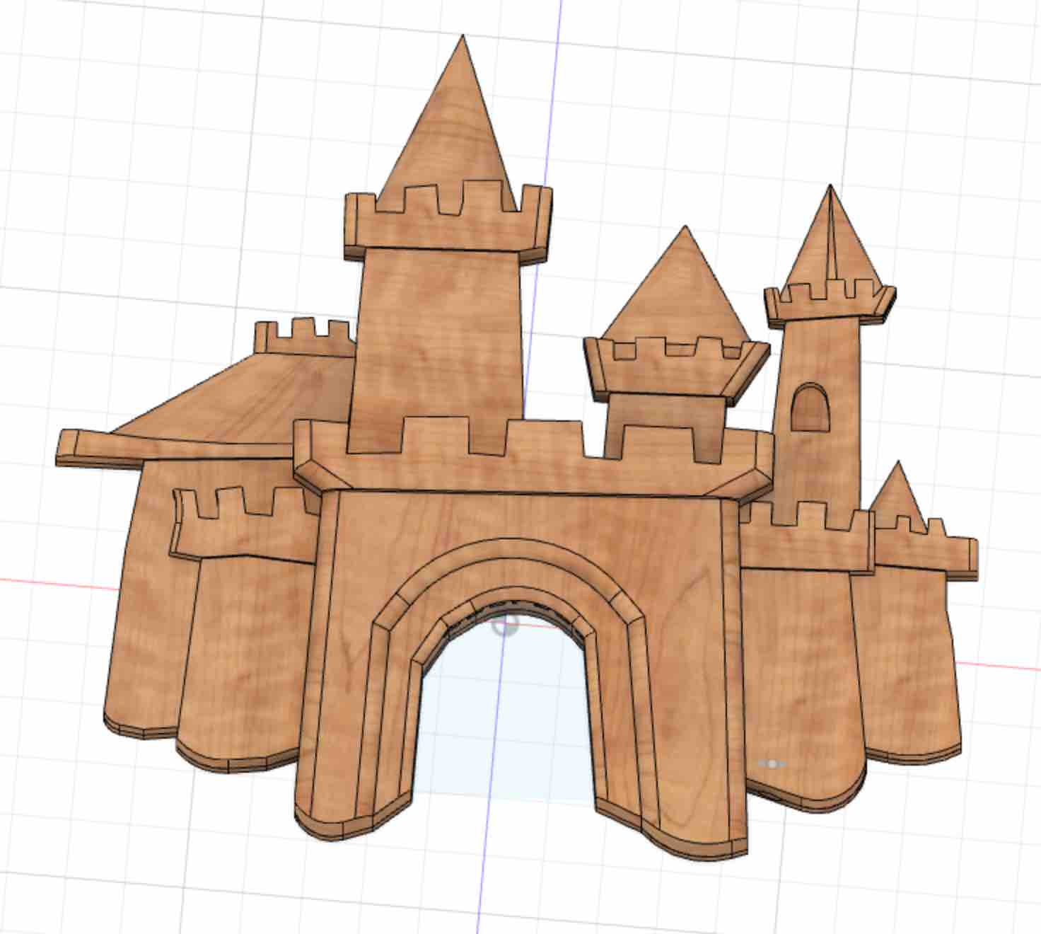
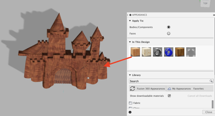
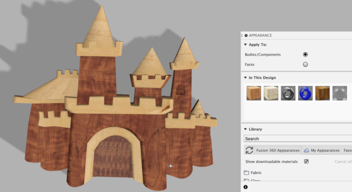
In the appearance menu, a catalog of different materials is listed. These can be dragged and dropped onto different bodies/faces of the design to change how it looks. I added different wood textures the different parts of the castle.
The environment menu works similarly. I chose the “Plaza” environment, after which the castle appears as if it is laying on the tiled floor of a plaza.
Summary
I really enjoyed this week. We were lucky to have such a great Fusion tutorial. By the end of the tutorial, I was a bit overwhelmed and could not keep up with how to make animation and componenets work, so i was glad I was able to figure these aspects of the software out at home. I was excited to be able to use Fusion more throughout FabAcdemy. The video I included would not appear when I uploaded it directly to my website, either as a compressed mp4 or webm, so I ended up using youtube. I found out no one in our FabAcademy group was able to upload directly, so curious if this is a GitLab issue or if it will get resolved.