Week 9 - Input devices
Assignment
Probe an input device's analog levels and digital signals
See the difference between the output of a sensor as:
Registered by a microcontroller
Via an analog measurement device
With the help of Henk we choose the distance sensor. We tried to install the sensor together remotely. We all had one board (NodeMCU) in common, so we decided to use it for this week's group assignment.
Setting up the NodeMCU for arduino
Each of us then connected the board to our computer and started up the Arduino IDE. We had to set up Arduino to work with the NodeMCU by adding the board. Under the files > preferences tab, add the link to the additional boards manager window. Add the following link: https://arduino.esp8266.com/stable/package_esp8266com_index.json. Then go to board manger and Add board, Search for ESP and install the board.
1. Registered sensor data by a microcontroller
We used the NodeMCU 1.0. We connected a Ultrasonic sensor. It consists of a transmitter and a receiver.
We had two different boards:
HC-SR05
3 pin board v2.0 (no type found)
The HC-SR04
From the datasheet of the HCSR-04,
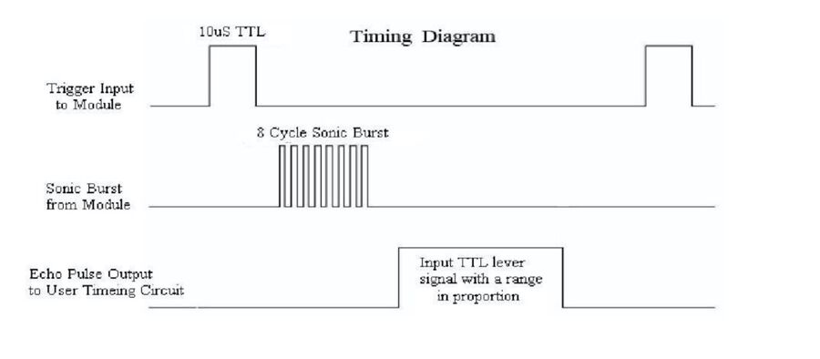
The module includes ultrasonic transmitters, receiver and control circuit. The basic principle of work: (1) Using IO trigger for at least 10us high level signal, (2) The Module automatically sends eight 40 kHz and detects whether there is a pulse signal back. (3) IF the signal back, through high level , time of high output IO duration is the time from sending ultrasonic to returning. Test distance = (high level time×velocity of sound (340M/S) / 2...
Source: datasheet HC-SR04
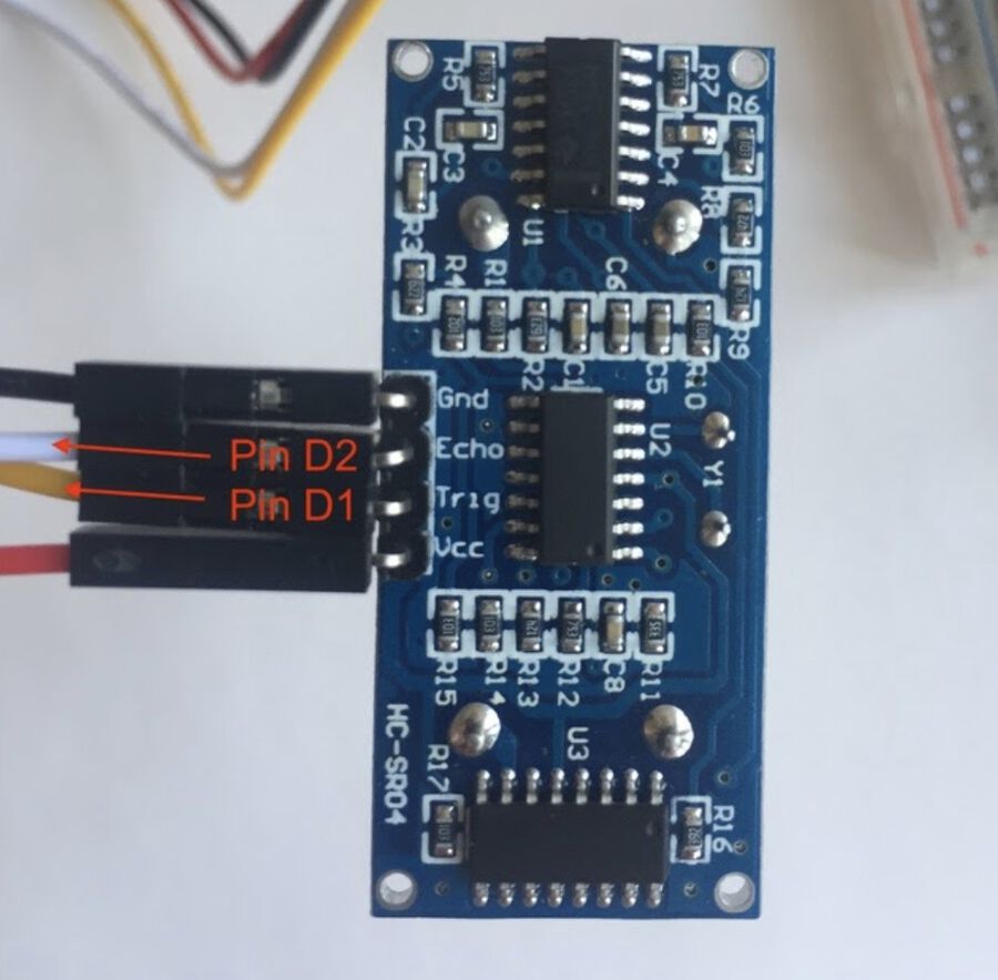
Connecting the HC-SR04 sensor
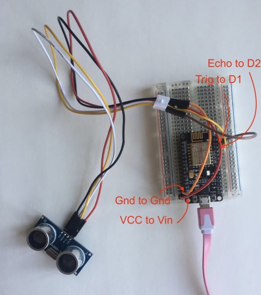
Hyejin, Harm and Nathan had a 4 pin HC-SR04. And connected the Trigger tot D1, and the Echo to D2. The VCC was connected to the Vin of the NodeMCU since this module only works on 5Volt.
We connected the VCC pin of the sensor to Vin of the MCU. The GND to GND, the Echo pin of the sensor to D1, and the Trigger pin to D2.
Code for the HC-SR04
Next we loaded the code unto the board. The code we used was:
#define trigPin D1
#define echoPin D2

void setup() {
Serial.begin (9600);
pinMode(trigPin, OUTPUT);
pinMode(echoPin, INPUT);
}

void loop() {
long duration, distance;
digitalWrite(trigPin, LOW);
delayMicroseconds(2);
digitalWrite(trigPin, HIGH);
delayMicroseconds(10);
digitalWrite(trigPin, LOW);
duration = pulseIn(echoPin, HIGH);
distance = (duration/2) / 29.1;

Serial.println(duration)
Serial.print(distance); Serial.println(" cm");

delay(100);
}
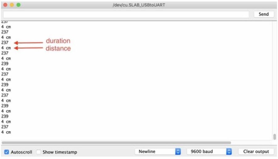
Output in the serial monitor of the Arduino IDE
Setting up the Ultrasonic Ranger V2.0 (Tessel)
Tessel had a different sensor, she did not have an echo and pulse pin. Instead she had an Ultrasonic Ranger V2.0. This one has only three pins. Next to VCC and GND there is a sig and nc pin. Nc stands for not connected, so this sensor has only three pins.
With the help of this documentation Tessel set it up:
This meant that a different code was needed to set it up. The code is not really good code, there is extra stuff that is not needed. But it does work.
const int pingPin = D1;
int M1 = 12;
int M2 = 13;
int C;
void setup() {
 // initialize serial communication:
 Serial.begin(9600);
 pinMode(M1, HIGH); //to control motor
 pinMode(M2, HIGH);
}
void loop()
{
 // establish variables for duration of the ping,
 // and the distance result in inches and centimeters:
 long duration, inches, cm;
 // The PING))) is triggered by a HIGH pulse of 2 or more microseconds.
 // Give a short LOW pulse beforehand to ensure a clean HIGH pulse:

 pinMode(pingPin, OUTPUT);
 digitalWrite(pingPin, LOW);
 delayMicroseconds(2);
 digitalWrite(pingPin, HIGH);
 delayMicroseconds(5);
 digitalWrite(pingPin, LOW);
 // The same pin is used to read the signal from the PING))): a HIGH
 // pulse whose duration is the time (in microseconds) from the sending
 // of the ping to the reception of its echo off of an object.
 pinMode(pingPin, INPUT);
 duration = pulseIn(pingPin, HIGH);
 C = digitalRead(duration);
 if (C > 2*cm)
 {
 digitalWrite(M1, HIGH);
 }
 else
 { digitalWrite(M1, LOW);}
 // convert the time into a distance
 inches = microsecondsToInches(duration);
 cm = microsecondsToCentimeters(duration);

 Serial.print(inches); // to serially print the data
 Serial.print("in, ");
 Serial.print(cm);
 Serial.print("cm");
 Serial.println();
Serial.println(duration);
delay(100);
}
long microsecondsToInches(long microseconds)
{
 return microseconds / 74 / 2;
}
long microsecondsToCentimeters(long microseconds)
{
 return microseconds / 29 / 2;
}
The code worked and we opened the serial monitor in the Arduino IDE. Here we could read the output of the sensor.
Here is a video of the output in the serial monitor of the Arduino IDE. Output alternates between distance and duration.
output ultrasonic sensor from Tessel Renzenbrink on Vimeo.
Register the sensor data via an analog device
According to the datasheet the pulse pin sends a signal (high voltage) to the Pulse pin on the Echo pin the received signal (audio) should be visible. The difference in time between the start of the pulse and the start of the echo is the time it takes till the sound bounces on a surface.

Source: datasheet HC-SR04
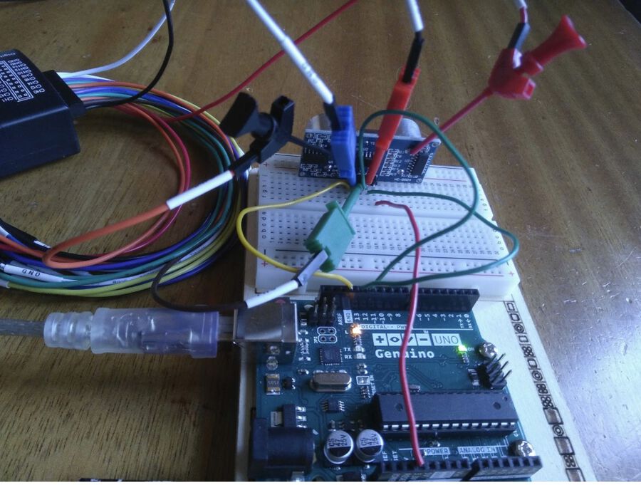
Working from home because of the pandemic, we asked Henk to connect one probe on the ECHO pin and the other probe on the Pulse pin. Set the voltage to 5V and the time Div to about 10 microseconds.
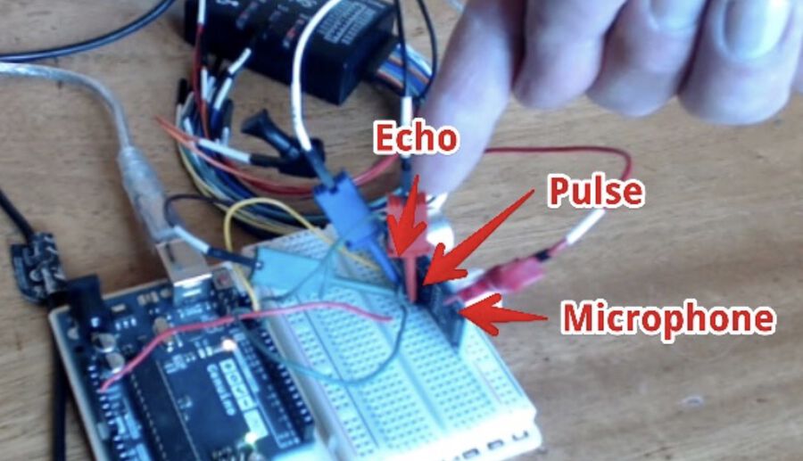
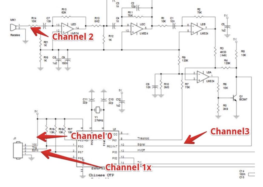
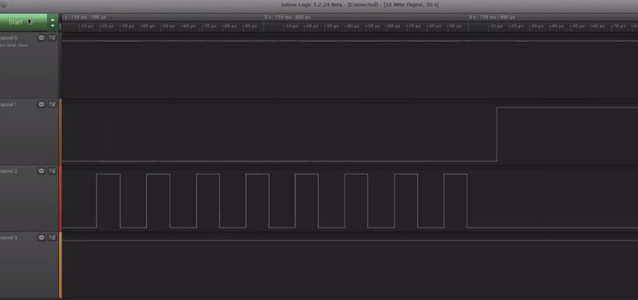
Channel 0 is connected to the trigger pin.
Channel 1 is connected to the echo pin.
Channel 2 is connected to the ultrasonic speaker
Channel 3 receives the echo’s.
The two pictures below show Henk measuring 4 channels. The left picture shows the logical analyzer connected to four pins. The right picture is the output of the logical analyzer.
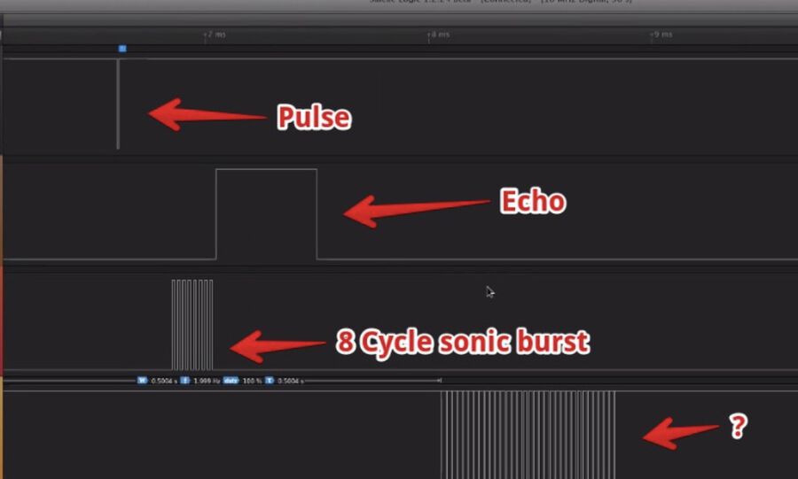
When the board is triggered it will send 8 sonic bursts. Also, it will put the echo pin to HIGH until it receives an echo back. The echo signal on channel 3 goes from small to bigger to small again. This is because it works like an echo when you scream in the mountains. You hear the echo back and then the echo of the echo of the echo.
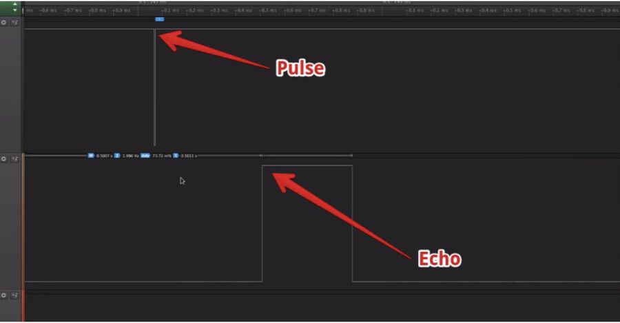
Pulse and Echo pins on the HC-SR04
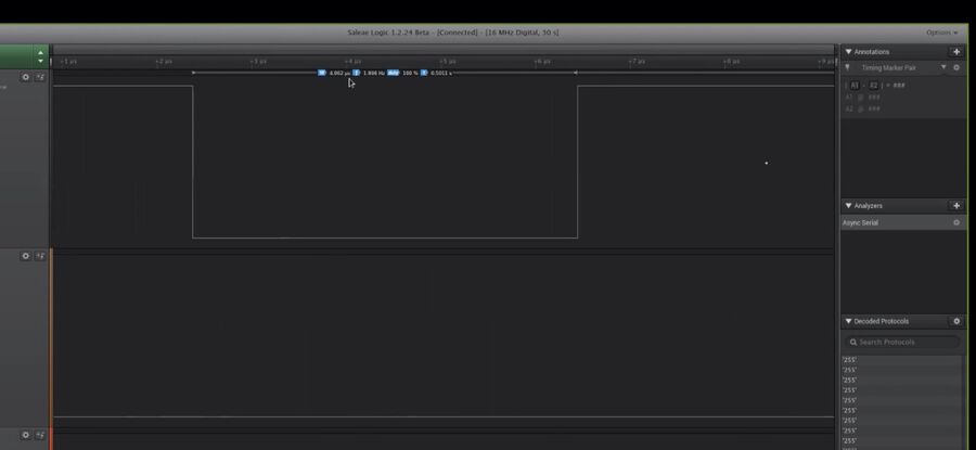
Length of the Pulse
Sonic burst
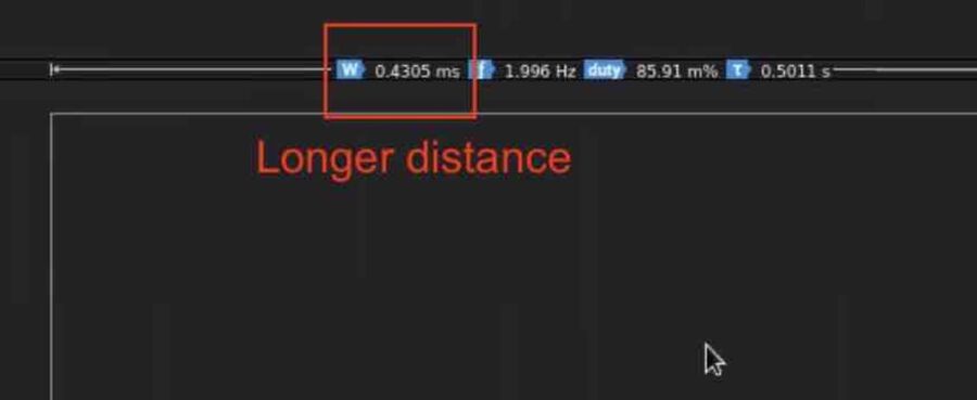
Henk measured two different distances with the sensor. You can see the outcome in the two pictures below.
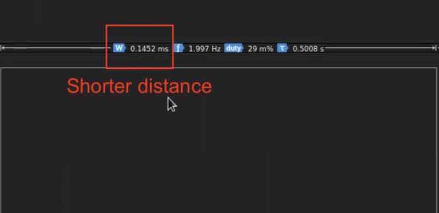
The shorter distance measured 0.1452 ms. Using this measurement you can calculate the distance.
// The speed of sound is 340 m/s or 29 microseconds per centimeter.
// The ping travels out and back, so to find the distance of the object we
// take half of the distance travelled.
The shorter distance that was measured is:
0.1452 milliseconds = 145.2 microseconds.
Sound travels at 29 microseconds per centimeter.
145.2 um / 29 = 5.007
This must be divided by 2, because the sound travels to the measured object and back again. Therefore the distance that was measured is 2.503 cm.
The longer distance that was measured is:
0.4395 ms = 439.5 um
439.5 / 29 = 15.1552
15.1552 / 2 = 7.5775 cm
The longer distance measured was: 7.5775 cm
Arduino code from an example for the ultrasonic sensor
 Ping))) Sensor

  This sketch reads a PING))) ultrasonic rangefinder and returns the distance
  to the closest object in range. To do this, it sends a pulse to the sensor to
  initiate a reading, then listens for a pulse to return. The length of the returning pulse is proportional to the distance of the object from the sensor.

  The circuit:
  - +V connection of the PING))) attached to +5V
  - GND connection of the PING))) attached to ground
  - SIG connection of the PING))) attached to digital pin 7

  created 3 Nov 2008
  by David A. Mellis
  modified 30 Aug 2011
  by Tom Igoe

  This example code is in the public domain.

  http://www.arduino.cc/en/Tutorial/Ping
*/

// this constant won't change. It's the pin number of the sensor's output:
const int pingPin = 7;

void setup() {
  // initialize serial communication:
  Serial.begin(9600);
}

void loop() {
  // establish variables for duration of the ping, and the distance result
  // in inches and centimeters:
  long duration, inches, cm;

  // The PING))) is triggered by a HIGH pulse of 2 or more microseconds.
  // Give a short LOW pulse beforehand to ensure a clean HIGH pulse:
  pinMode(pingPin, OUTPUT);
  digitalWrite(pingPin, LOW);
  delayMicroseconds(2);
  digitalWrite(pingPin, HIGH);
  delayMicroseconds(5);
  digitalWrite(pingPin, LOW);

  // The same pin is used to read the signal from the PING))): a HIGH pulse
  // whose duration is the time (in microseconds) from the sending of the ping
  // to the reception of its echo off of an object.
  pinMode(pingPin, INPUT);
  duration = pulseIn(pingPin, HIGH);

  // convert the time into a distance
  inches = microsecondsToInches(duration);
  cm = microsecondsToCentimeters(duration);

  Serial.print(inches);
  Serial.print("in, ");
  Serial.print(cm);
  Serial.print("cm");
  Serial.println();

  delay(100);
}

long microsecondsToInches(long microseconds) {
  // According to Parallax's datasheet for the PING))), there are 73.746
  // microseconds per inch (i.e. sound travels at 1130 feet per second).
  // This gives the distance travelled by the ping, outbound and return,
  // so we divide by 2 to get the distance of the obstacle.
  // See: http://www.parallax.com/dl/docs/prod/acc/28015-PING-v1.3.pdf
  return microseconds / 74 / 2;
}

long microsecondsToCentimeters(long microseconds) {
  // The speed of sound is 340 m/s or 29 microseconds per centimeter.
  // The ping travels out and back, so to find the distance of the object we
  // take half of the distance travelled.
  return microseconds / 29 / 2;
}