Design and Testing: Fusion 360
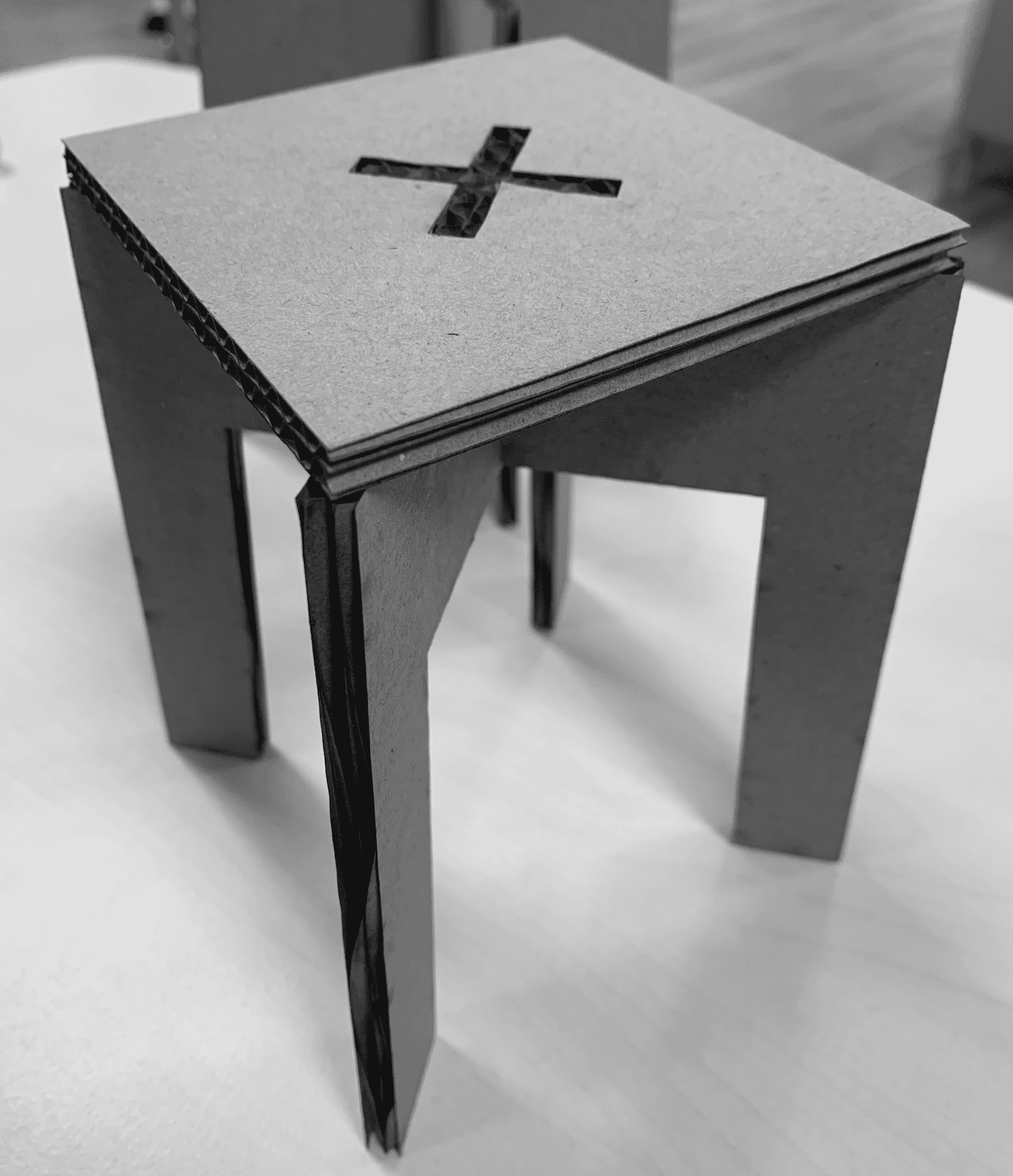
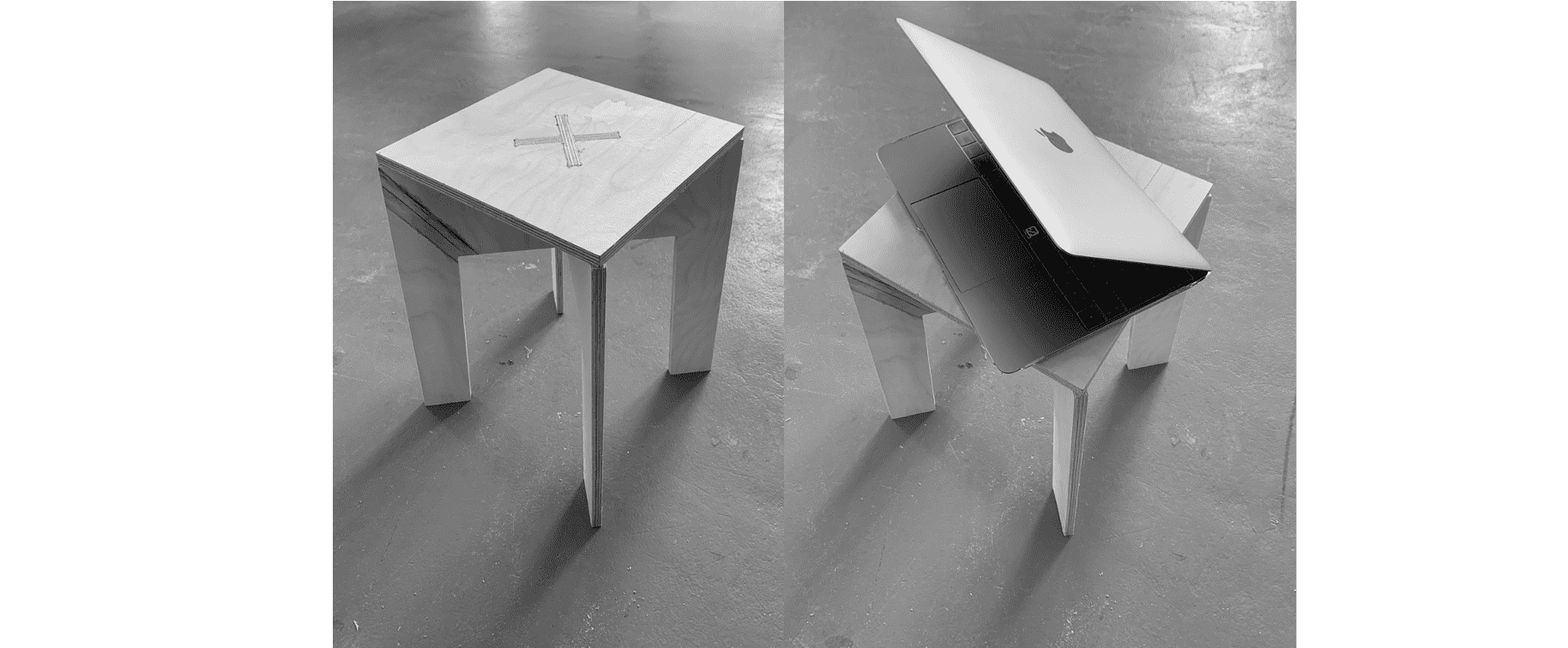
For this week, i decided to make a simple pressfit table stool. I designed it using fusion since i'm more comfortable with it and i'm learning more and more features throught this course. I began with a 2D design and then converted it to 3D using the normal steps i used previously. For the aesthetic aspect, i changed the appearance using the appearance feature to mimic the real look.The feature i used to ensure that the legs can fit together with the table-top on. After that, i exported the 2D file as dxf to cut a small scaled down version using laser on cardboard to make sure that dimensions and design fits well. Then going back to fusion, i layed out all parts on one flat sheet and exported it to prepare for CNC cutting process.
Downloads
Downloads
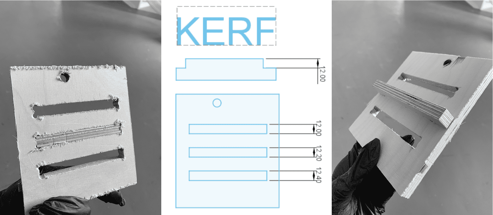
Finding Kerf
Before we proceed, we need to find the kerf for the 12mm plywood material we are using so we can incorporate it in the design. A simple pressfit design was made for this test and 3 different measurements were chosen as a start. Fillets used here and also will be used in the final design are the Dog bone fillets, which are used to create clearance for internal corners to allow slotted pieces to fit together.The cutting process will be explained below.The best fit was on 12.20mm which makes kerf=0.2mm.
Preparing files for cnc: Vcarve
Here we will start working on generating toolpaths in g-code for the CNC. Plywood sheets must be placed and screwed into the correct position. Then the following steps are followed:
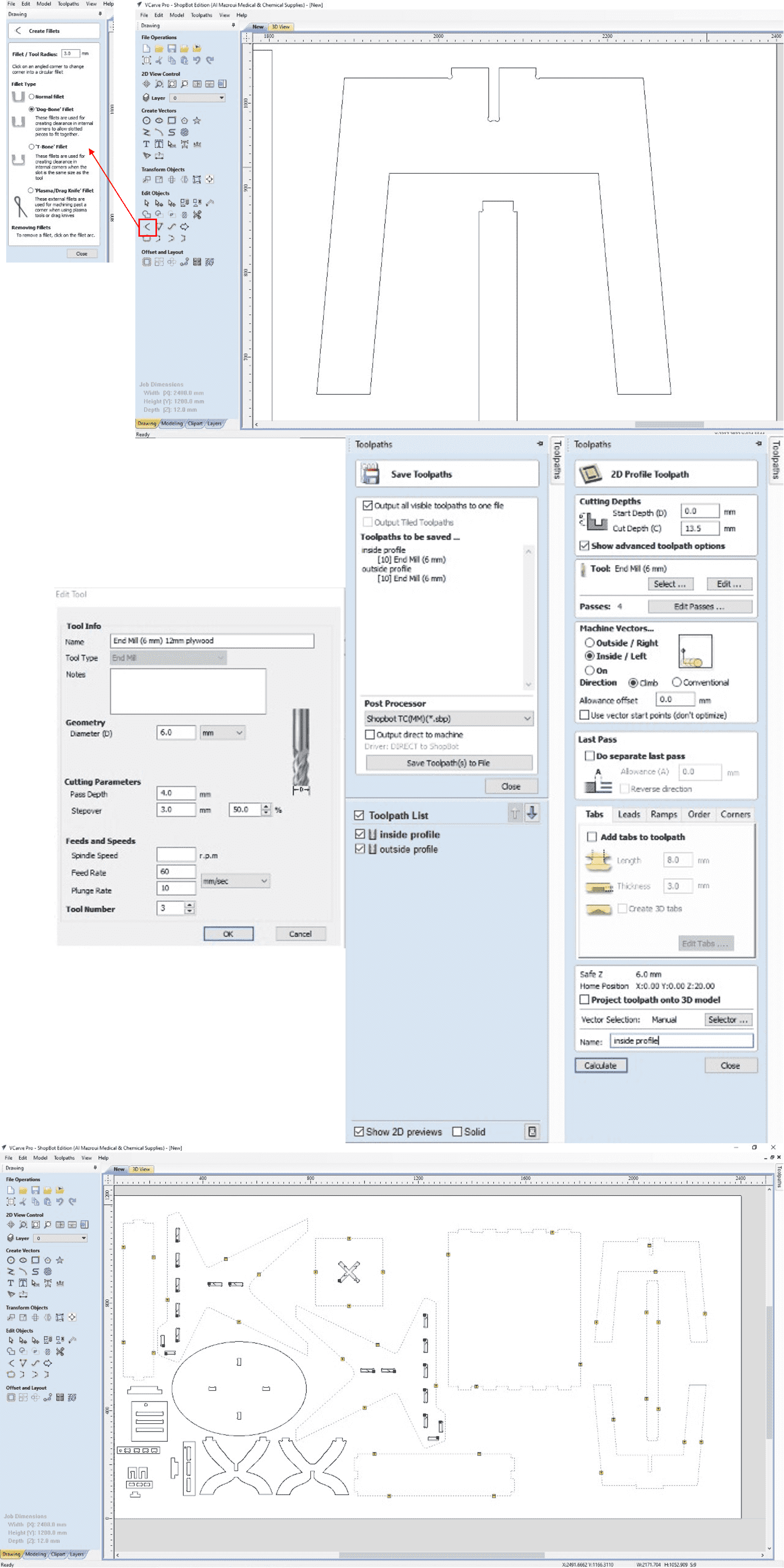
- Import the design in Vcarve software, making sure that sheet dimension is measured and inserted under Job Setup Tab, in addition to specifying material thickness (12mm in our case).When placing the design, we must always pay attention to the location of screws to prevent the end mill from passing over it and breaking.
- As mentioned before, Dog fillets will be used, for both slots and taps corner. Fillets are inserted in the design in this step.
- We will be creating 2 profiles, 1 for cutting the inner parts, and another for cutting the outer parts. Start by going to toolpaths tab and select profile toolpath with the following settings:
Inside Profile- Cut depth = 13.5mm (slightly larger the depth of plywood to ensure a full cut)
- Tool> 6mm End Mill, Spindle Speed=14000r.p.m, Feed Rate=60mm/sec, Plunge Rate=10mm/sec, Passes=4 (the higher the number of passes, the more steps it takes for the end mill to go down to cut, which makes it safer as it wont impose high load and damage it).
- Machine Vectors> Inside/left , Direction=Climb.
- Tabs > Tick add tabs, Thickness=3mm, Length=8mm. Tabs location can be changed based on our own preferenecs.
- Name the profile = Inside Profile, then press Calculate.
- Same exact steps are followed, the only difference is when choosing the machine vectors, where we choose> Outside/Right, then Rename the profile to Outside Profile and click on Calculate.
Preparing Shobot: ShopBot SB3
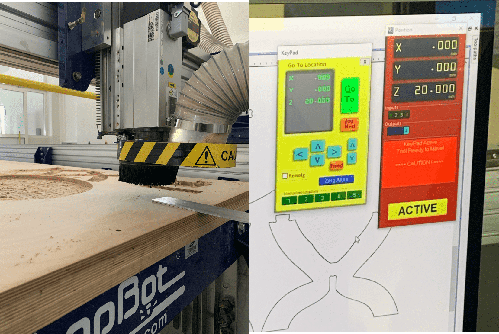
Similar to any milling/cutting machines, the XYZ origin points must be set. We open the ShopBot SB3 software then we do the following:
For X & Y position=On the control Panel click on the keypad, then move using the on screen arrows or using the remote control that is connected, then click on Zero Axes and tick the X & y. For Z position= we first move to a reachable spot, then take the metal plate that is attached on top of the tool, and place it underneath the tool position, then click on set zero, and it'll automatically go down and make the milling bit touch the metal plate twice. Now Z axis is zeroed. Now we can start the milling process by clicking on "cut" from the control panel, then warning messages will appear and we should read them carefully, then we click on start from the remote control
Results
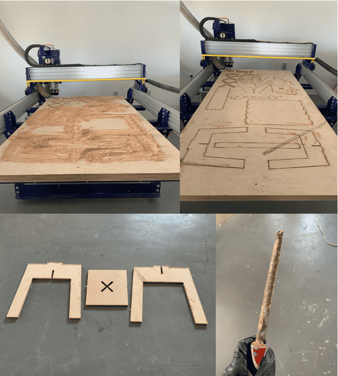
During the milling process, it is always recommended to stay around to monitor in case anything occured that might interrupt the process, keeping the emergency button near.
The process went very smooth, after it was done. We vacummed the extra residues that formed so we can start breaking the tabs and remove the parts.
The edges weren't smooth and thus required some sanding to look good.
After that we are ready for assembling, which needed a bit of power to do so and got help from my friends. Final result looked really good.
During this assignment we worked in groups to use time efficently especially for this machine, which is why in the pictures it is shown that the sheet contained other designs.
Group Assignment
For this task, we need to do the following:
Test runout, alignment, speeds, feeds, and toolpaths for the machine.
The link to the group assignment page is found here.
Experience
One of the toughest and most dangerous weeks, safety is a must, knowing what incidents took place with this machine previously made us more cautious but didn't prevent us from enjoying it!