Group Assignment
For this task, it is mainly done through groupwork. The group assignment will cover the following:
- Design a machine that includes mechanism + actuation + automation.
- Build the mechanical parts and operate it manually.
- Document the group project.
- Actuate and automate your machine.
- Document the group project.
A Brief
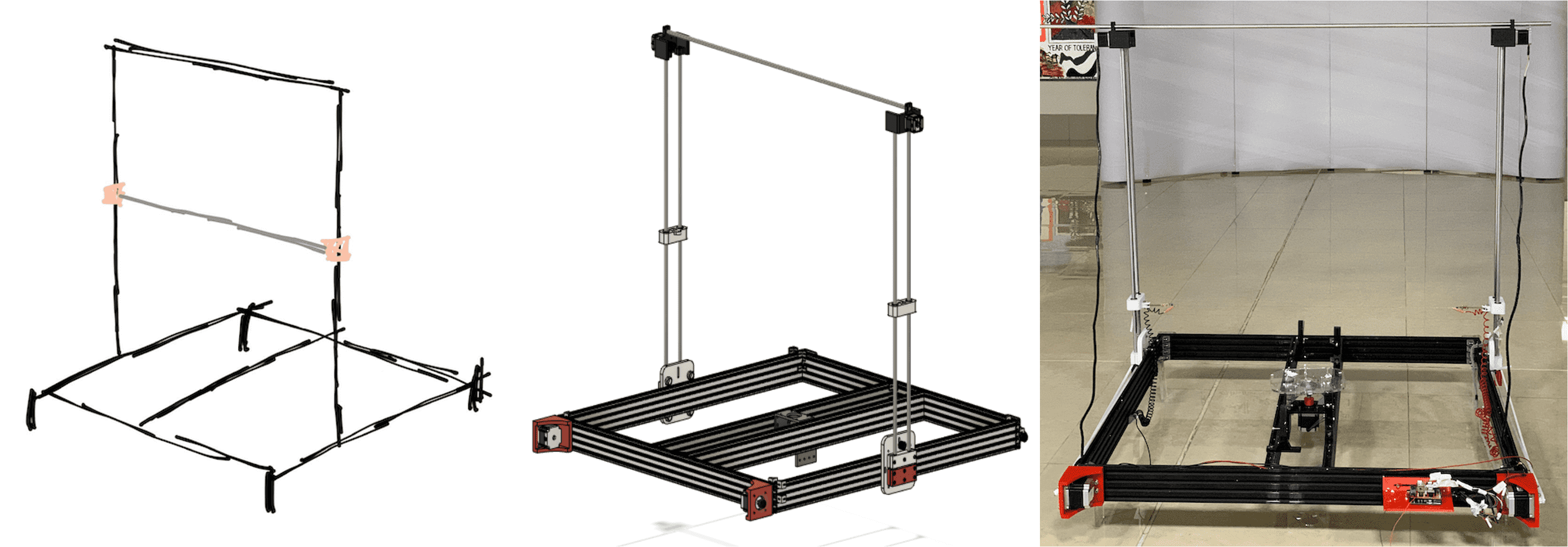
For this week, we chose to make a CNC Foam Cutter since when we looked into all the different machines available in our lab, non of them were related to foam cutting which will give a unique addition to the Lab Machines.
Even though we divided the main tasks on each on of us, but we all worked together as one team and contributed in all tasks even if it was minimal.
As for the assigned tasks, Fatma & I were given the Rotating base as our main task.
Initial Design
Fatma and I had several Ideas about the initial design. We needed to know the base structure material to know how we will be attaching and what weight it could handle. So we began first with the shape and mechanism of the base.
- Round Shape Base with cylindrical part attached to it from below in center,3D printed.
- Motor to be connected to the base through the motor shaft by inserting it in the cylindrical part.
- The whole part will be attached to the machine structure (whether it is aluminum or rod) using the same 3D printed base with and extended part from the cylinder to stick to the motor and from the other side get attached to the structure.
- The base of the cylider will carry the load of the motor, which might not be rigid enough to handle the weight with movement.
- 3D printing the round base will impose limitation on the design size since it will be limited by the 3D printer printing space, and will consume more time the more we increase the size, it will also get heavier and will require a more rigid structure.
Final Design
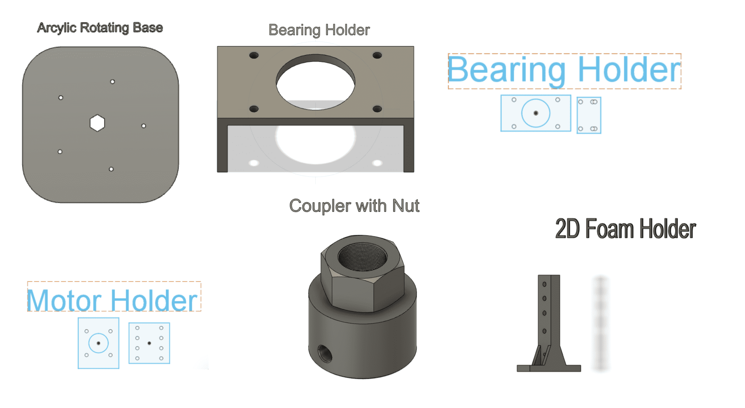
The design went through alot of modifications, since also the main structure changed several times so we had to adapt.The final structure was chosen to be made from Aluminum profile size 20x80 mm , with to profiles running in the middle where in between the rotating base must be placed.The following are the parts that made up the final base:
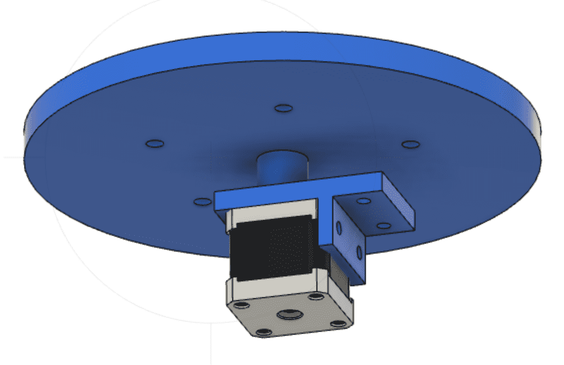
12 mm Acrylic rotating base: shape is changed to Square with rounded corners, with center hole with the shape of the M12 Bolt that will be inserted.The acrylic base also have holes for inserting bolts with the tip facing down so that the legs serve as a stand for foam to insert and to fix during the cutting.
Then the bolt passes through the bearing that is pressed firmly using 2 nuts and washers from top and below ,onto another acrylic base that is tightened and fixed on the aluminum profile to distribute the load onto the profile since it can tolerate. Bearing are used here to assist the rotation of the motor and to make it smooth.
Then the bolt will continue to pass until the 3D printed Nut_Coupler, the bolt will stop at the end of the nut to meet in contact with the shaft of the motor that passes through the coupler, this is to ensure the rotation.
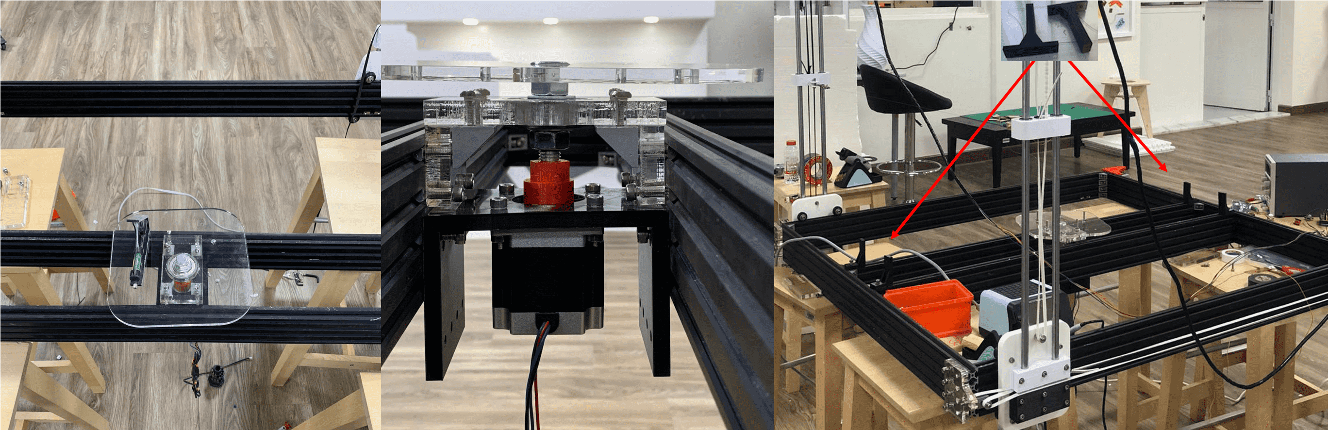
Then the Nema 34 Motor is attached to a 3d printed holder that is fixed onto the aluminum profile to distribute load and not to make it direct held by motor. The height of holder was longer than the profile since the decision of changing the size of aluminum profile from 20x40 mm to 20x80 mm was made after we printed.
The 2D foam holders were an extra part that were designed later, to be fixed using screws and nuts onto the edge of the Aluminum profiles that will be placed in the middle, 4 pieces were 3D printed.
Some of the prorblems that we encountered after the execution of the machine are:The base rotation wasn't very smooth unfortunately, the solution to this is to use a ready coupler that can fit into the shaft and thus aid the rotation, since the coupler we used was 3D printed.
After pressing the bolt into the acrylic base, the angle of the base was a bit tilted. This can solved if we 3D printed the base with bolt hole that is coiled to fit with the bolt to ensure the fit of it.
Downloads
Some of the prorblems that we encountered after the execution of the machine are:
Other Tasks
As i said before, even though we divided the tasks among us us, but we all worked together as one team and contributed in all tasks. I worked and assisted on the following:
- To draw the Preliminary Sketch using the iPad
- Designed,Cut, and assembeled the limit switch holder with Fatma.
- Verified the functionality of the limit switch by making a simple code on arduino and load it just to make sure everything is working right.
- Arrangment of wires after attaching all electronics.
- Assembling other parts on the structure.
Experience
I really loved this week, even though the pressure of finishing it within one week was very stressful, but we enjoyed each part of it. The fact that we designed and made a machine that is functional during the conditions that COVID-19 pandemic imposed, is really amazing. Team work is the best part of this week.