Preparing the board files before Milling
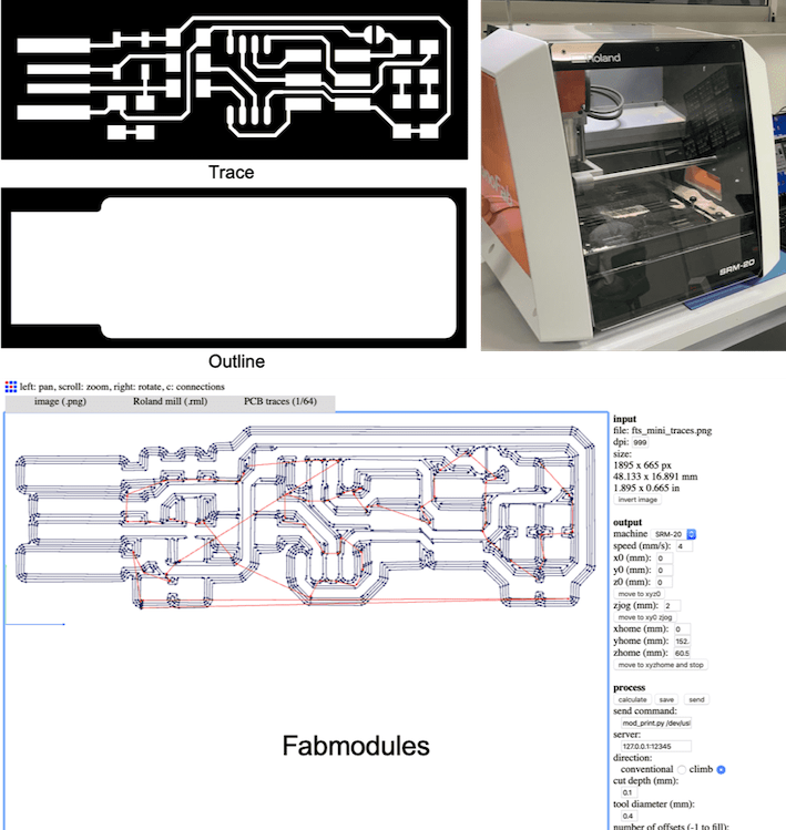
- The schematic that will be printed was given to us for the purpose of saving time as attached from Building the FabTinyISP:PCB Fabrication, since another board will be created from scratch later. The schematic is exported twice as a monochrome image, one for traces and one for oultine, which are both required for milling the board.
- The 2 images are then uploaded on Fabmodules. The traces will be milled with a 1/64" bit and the outline with a 1/32" bit. We will be milling FR1 boards (a paper substrate) with a Roland SRM-20 milling machine. The steps are as follows:
- For the traces, choosing the input format (png in our case) to insert the image, the output format is Roland Mill(.rml) with refernce to the machine we are using, and then choosing PCB Traces (1/64) with refernce to the size of the milling bit. On the right we choose the machine in the output section (SRM-20) in our case, making sure to zero the x,y,z.Then we click on calculate and then save the file, now it is ready to be used with the machine.
- For the outline, the same exact steps are followed, the only difference is the process where it is chosen as PCB outline (1/32) again this is with refernce to the milling bit size.
- Now the images are ready to be used for milling.
Milling The Board
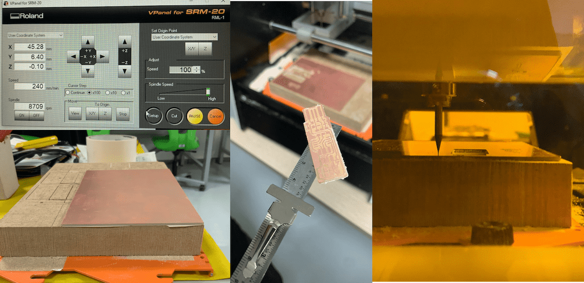
- Using an MDF board that is cut on the size of the milling machine plate, the FR1 copper plate was attached on it using double side tape and pressed on firmly, and to ensure it's properly atached the board was tapped with a hammer, making sure that the plate is in the same level of the board, since any unlevelling might affect the accuracy of the milling process.
- The board should be attached to the machine plate using the available screws. An important note is that the screws should be fixed in a diagonal manner to avoid fixing it in an unlevelled way.
SMD Soldering
When the PCB is ready, Surface Mount Device will be used for soldering the components. Following the steps from Building the FabTinyISP:
- The copper in front of the pads must be removed found at the edge of the board in front of the USB contacts.
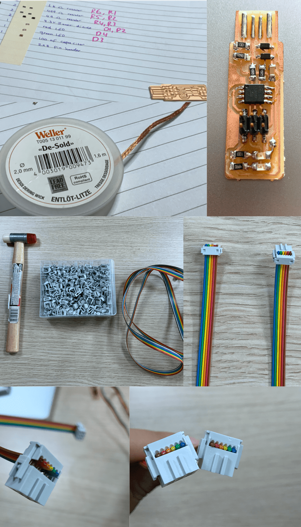
- After arranging all components, soldering starts, making sure that the schematic is followed.A very helpful technique that i found useful for solering using SMD, is placing some of the melted solder wire on pads,then place the component on top and melt the solder, this will ensure that its fixed to the required location, then more solder can be added to ensure the connection is made.
- If any connection was made wrong or soldering wasn't correct, which i did face during the process, a very easy way to remove the solder is using the Desolder Copper Wire by just placing the wire on top of the unwanted solder and then melting it, this will make the unwanted solder to be attached to the wire and then to remove the wire quickly while the solder is melted, if the solder was warm it might remove the copper layer on the PCB.
- After checking visually that all connections are made as per the schematic, a final and important check up is to be made using the multimeter which checks for any short circuit connections.
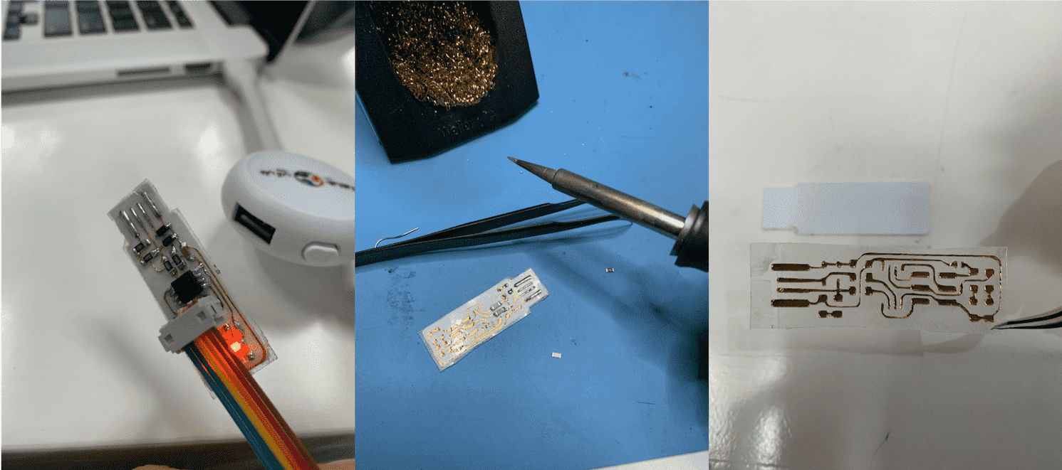
- 6 wires were pulled from the ribbon cable provided since headers have 6 pins each.
- Then the wire is inserted to headers from both ends, making sure insertion is in same order in both headers since each wire will be used on same pin for both ISP.
- After inserting, the hammer is used to press on the wires and fix them within the headers.
Programming
- As mentioned before, the steps on Building the FabTinyISP: website were followed, but unfortunately Mac Users will have to do few things in a different way.
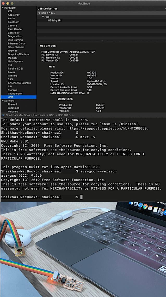
- Mac section on the website states that we need to download crosspack, a development environment for Atmel’s AVR® microcontrollers running on Apple’s Mac OS X, similar to AVR Studio on Windows, which was done, but no commands were provided to verify whether the installation was successful or not. So I followed the Windows section commands Using the GNU AVR toolchain on Windows 10 Specifically the last step which is the Sanity Check.
- On terminal, Make -v is entered to check the GNU version and to ensure it is properly installed since crosspack consists of the GNU compiler suite, a C library for the AVR, the AVRDUDE uploader and several other useful tools.
- After that, avr-gcc --version is entered, the version should also be displayed but unfortunately Mac users couldn't see this. Here i began searching and looking for a solution for this problem. I found a website that explains how to setup AVR-GCC toolchain on Mac OSX called Maxembedded. It stated that Homebrew must be installed first which was done using the command:
ruby -e "$(curl -fsSL https://raw.githubusercontent.com/Homebrew/install/master/install)
- After that we can use brew commands to install avr-gcc, brew tap osx-cross/avr was entered to install the latest version of avr-libc. If the commands didnt work or error message was displayed, try closing the terminal and reopen it again which i found it helpful, or enter the command mentioned in this website Brewinstall. This command will work on all steps after that which include installing gcc, binutils, and avrdude.
- The followings commands were then entered:
- Brew install binutils
- Brew install gcc
- Brew install avrdude
- Finally after entering the command "avr-gcc --version", the version was displayed meaning that everything was installed successfully and we are ready to move onto the next step
- Back to Building the FabTinyISP , moving to Get and Build the Firmware, the firmware source code was downloaded, then using the terminal to enter to the source code file using cd command, "make" command was entered, which created the hex file that will get programmed onto the ATtiny45, the created file is called fts_firmware.hex.
- To start programming the ATtiny45, the board must be connected to the computer/laptop. Here i did face a problem and also other mac users did since the laptop couldnt recognize the USB, for others they solved the problem by just changing the USB port and using a USB 3 hub, for me since i only have one port with an extender, i had to try several times until my laptop was able to recognize, though i didnt understand why it took so long. After that, the ISP programmer was connected the board using ribbon cables, ensuring the wire arrangment is similar on both boards.
- The following commands were entered:
- make flash : which will erase the contents of my board, and program its flash memory with the contents of the .hex file that was built before.
- make fuses: which will set up all of the fuses except the one that disables the reset pin.
- make rstdisbl: which will do the same thing as the previous command, but this time it's going to include that reset disable bit as well, and with that, avrdude will never be able to talk to this chip again through the ISP header.
Group Assignment
In the group assignment, we had the opportunity to try different material and methods for creating a PCB such as:
- PCB using the Vinyl Cutter
- PCB using the Fiber Laser
- Using mods instead of fabmodules to produce the files for milling
Experience
This was my first time printing a circuit board and building it and finally activating it. Knowing that you can make almost anything gives you the motive to continue to learn more. Ofcourse no experience is free of obstacles.The difficulty i faced was due to the fact that i'm a mac user and most users are using windows, also since different updates and different versions of macbook are there, its very hard to find someone using a mac product with same experience, but searching is the key to solving and overcoming all obstacles that are faced.