LCD
Liquid Crystal Display or the LCD, is a type of flat panel display which uses liquid crystals in its primary form of operation.The display I’m using is a 16×2 LCD display.It’s called a 16×2 LCD because it contains 2 lines, and can display 16 characters per line. Therefore, a 16×2 LCD screen can display up to 32 characters at once. It is possible to display more than 32 characters with scrolling though. I followed Arduino tutorial on Hello World for connecting and using the code to simulate on TinkerCad.
Downloads
Downloads
SG90 servo
Servo’s are very important in electronics, they are motors with a geared output shaft which can be controlled to turn one angle at a time. They require a signal pin which is used to tell the servo what angle to turn to or what degree of rotation it should make.Internally, they have a motor driver and a feedback circuit that makes sure that the servo arm reaches the desired position. They receive square wave similar to PWM signal on the input pin.
Servo motors usually have very high torque and are used in robotics and several other applications majorly because of the ease with which their rotation can be controlled. They have high current requirement so when using more than one servo motor with the Arduino, it is important to connect their power connections to an external power supply as the Arduino may not be able to source the current needed by the servo. Servo motors have three wires: power, ground, and signal.
Downloads
Servo motors usually have very high torque and are used in robotics and several other applications majorly because of the ease with which their rotation can be controlled. They have high current requirement so when using more than one servo motor with the Arduino, it is important to connect their power connections to an external power supply as the Arduino may not be able to source the current needed by the servo. Servo motors have three wires: power, ground, and signal.
- Red = +5v
- Brown = GND
- Orange = Signal PWM (pin 9 for this code)
Downloads
Final Project Output Device
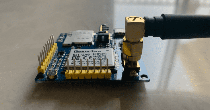
SIM Module IOT A6
For my Final project, i will be using the Sim module with Arduino to send the alert messages to the receiver side which should be the authority. Before beginning, i had to buy a number with sim size suitable with the available holder on the module, in addition to buying data and voice packages for the number so that i can use it. The connection is as follows:
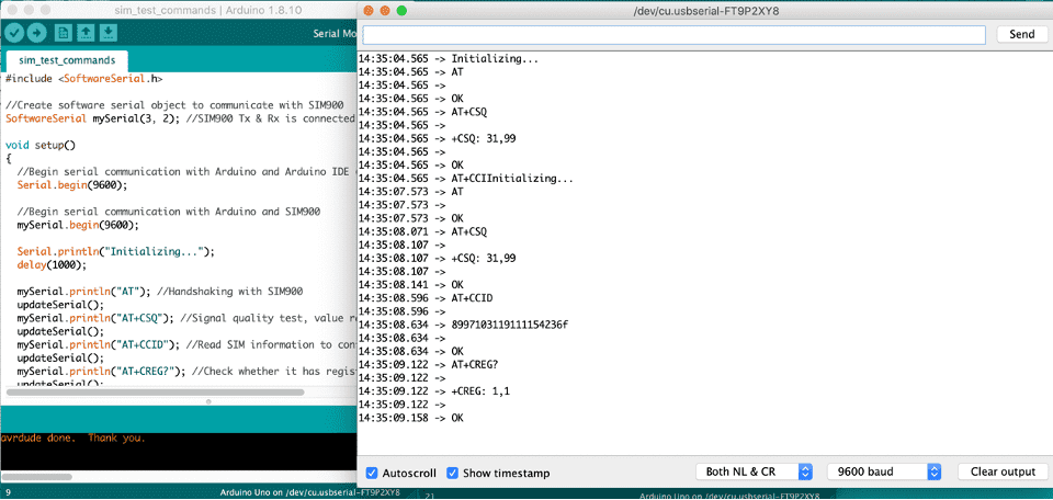
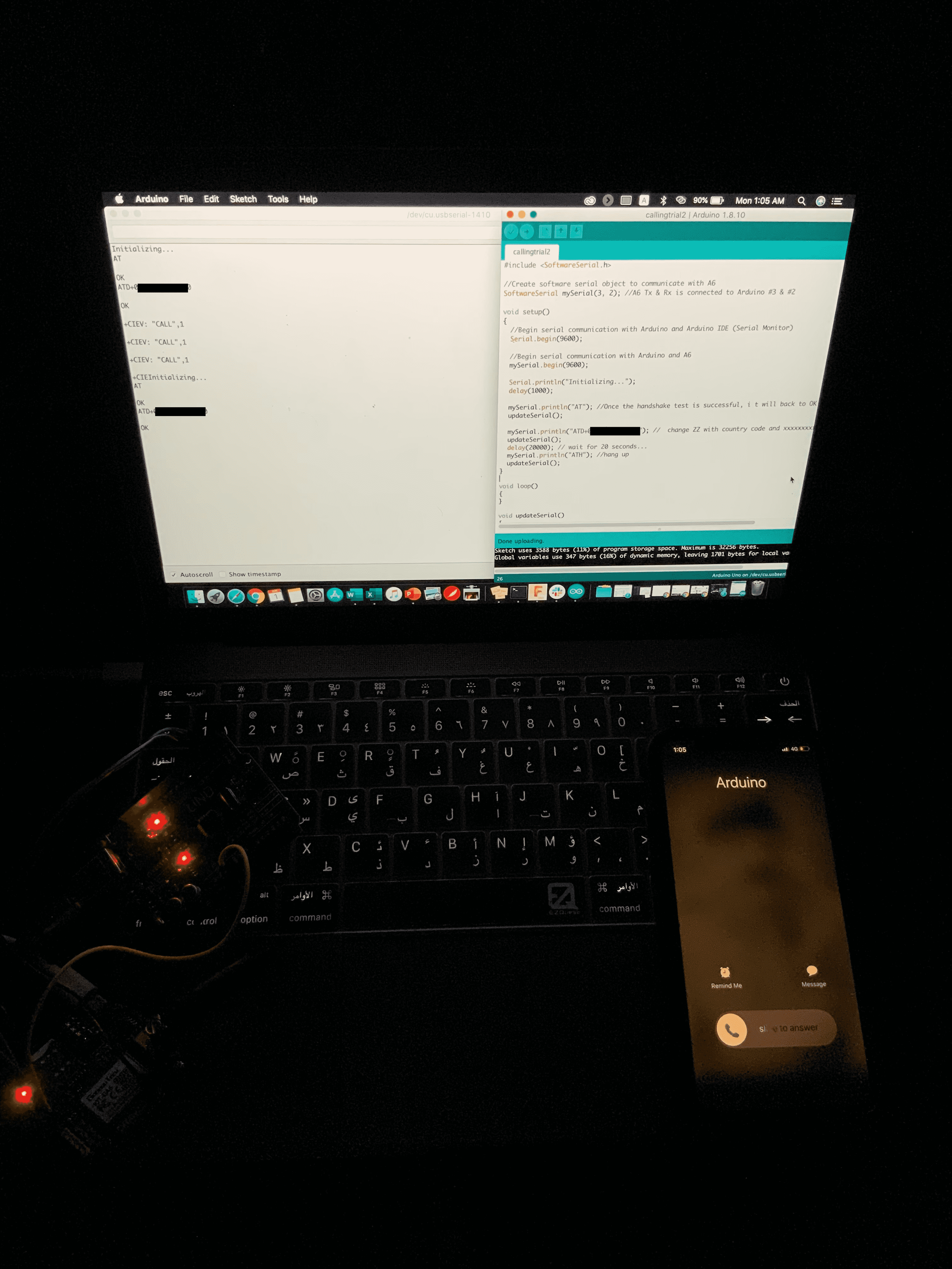
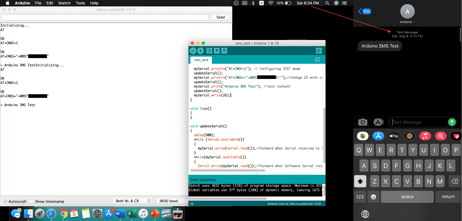
After that i tested calling a number and the result is shown, i do faced some errors which i didnt't really find an answer, sometimes restarting works, and sometimes i change the number format (removing + sign) and it works. For the project i will be needing to send the alerts as messages, which i tested at last. The main difference between the calling code and the sms code, is that after handshaking, the modes are chosen, ATD for calling, AT+CMGF=1 for configuring text mode.
Downloads
- To be powered externally through pins or mini usb cable.
- PD2 Tx (software serial) to U_RXD of sim.
- PD3 Rx (software serial) to U_TXD of sim.
- If it was connected through the mini USB, PWR pin on sim module to be connected to the VVC_IN on the sim module.
- Connect GROUND to common ground on PCB
After that i tested calling a number and the result is shown, i do faced some errors which i didnt't really find an answer, sometimes restarting works, and sometimes i change the number format (removing + sign) and it works. For the project i will be needing to send the alerts as messages, which i tested at last. The main difference between the calling code and the sms code, is that after handshaking, the modes are chosen, ATD for calling, AT+CMGF=1 for configuring text mode.
Downloads
Group Assignment
For this task we need to measure the power consumption of an output device, i chose the servo that is mentioned above, but this time i used by final project PCB instead of the arduino. I connected the power supply to my board with the servo connected. Using the Power rule: P(w)=V(v)*I(a)=> P=5V*0.1A=0.5W.
Experience
A very intresting week since i got the chance to explore different output devices and test the functionality of them. Of course i wasn't able to try all sesnors but i'm sure i will whenever i get the chance.