Fusion 360: CAD
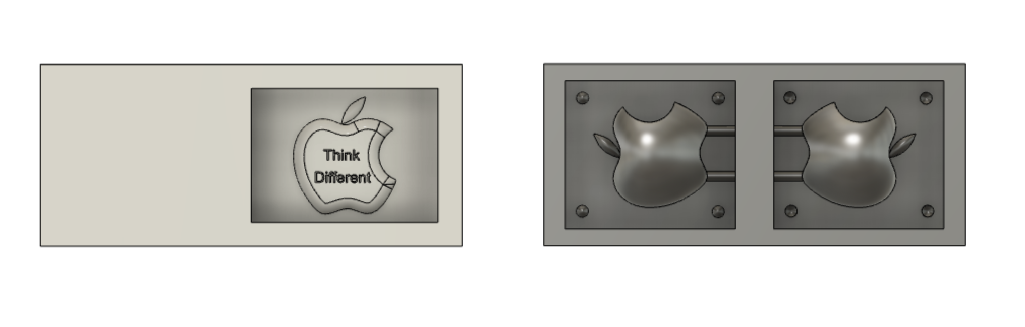
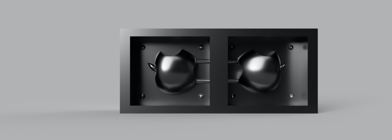
For the mold , i chose to design the Apple logo and made 2 versions of it , one for the one sided moumoldld and the other for the 2 sided mold where the result will be a 3D.But due to insufficent time i was able to only proceed with the 2 sided 3D mold. After Designing the apple 3D, the design should be split into 2 to be placed inside the wax stock, we took into consideration the size of the available wax stock.After designing the rectangluar wax box, 2 squares were designed for the apple halves to be placed symmetrically. It should be mirrored or else the results won't be accurate, some of the important features that can help to acheive that is the Mirroring feature and the Midplane. Then, some additions are required for the mold: 1) spheres to act as a pressfit mechanism for the boxes to get attached during casting, 2) cylindrical tubes for injecting the casting material.Now the design is ready to start preparing the CAM files.
The 3D view is found here: Apple
Downloads
The 3D view is found here: Apple
Downloads
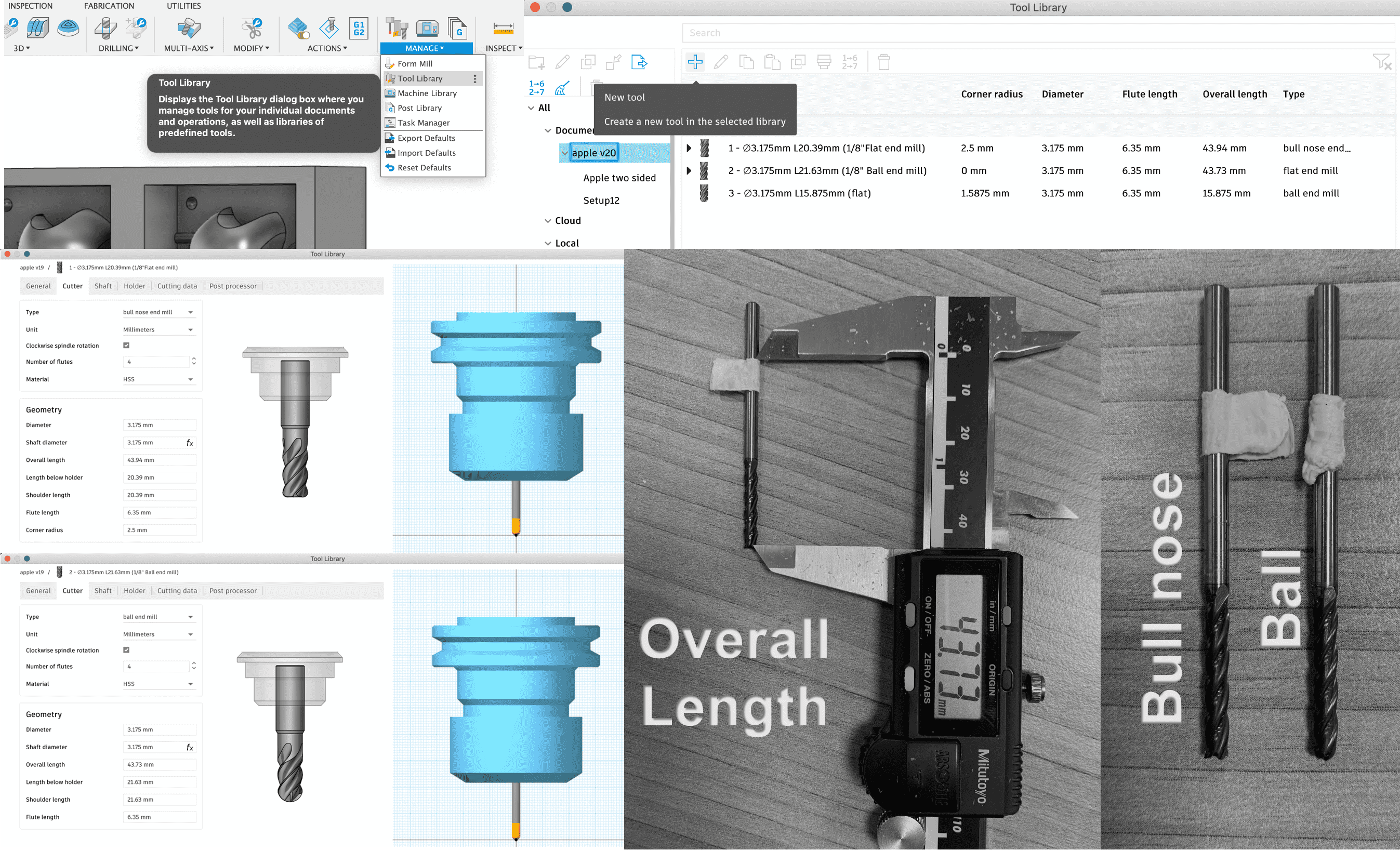
Fusion 360: CAM Tool Library
After finalizing the design, CAM files are required to be generated from Fusion 360 Manufacture to work with Roland SRM-20 CNC machine. Manufacture Tab is chosen where Tools are added from the Tool Library. Before choosing the tools, the end mills are measured after specifying the height (with a tape as shown in the pics) in which it will be the perfect position, since wrong placement might result in the milling bit either working in the air or pressing too hard down which will end in damaging it. The 2 end mills that will be used are:
- Bull-Nose end mills: for general purpose milling applications, they have a 90° profile , 4 flutes.
- Ball end mills: ideal for 3D contouring because they are less prone to chipping and leave a nice rounded edge, 4 flutes.
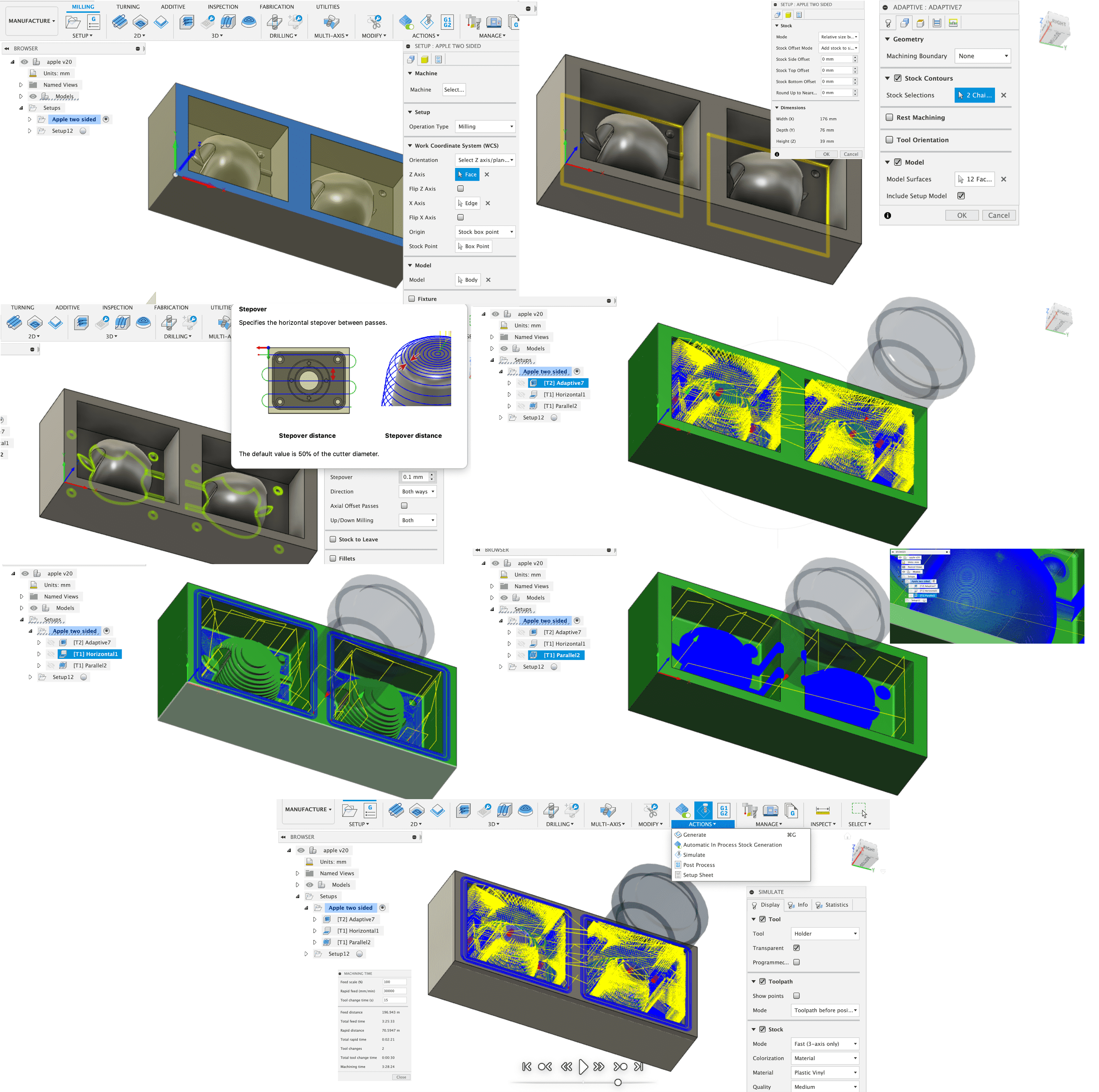
Fusion 360: CAM Toolpaths & Simulation
To begin the milling setup, there will be 3 consecutive processes:
Now we can simulate and check for errors and also can see the machinning time for the whole process and for each individual process.
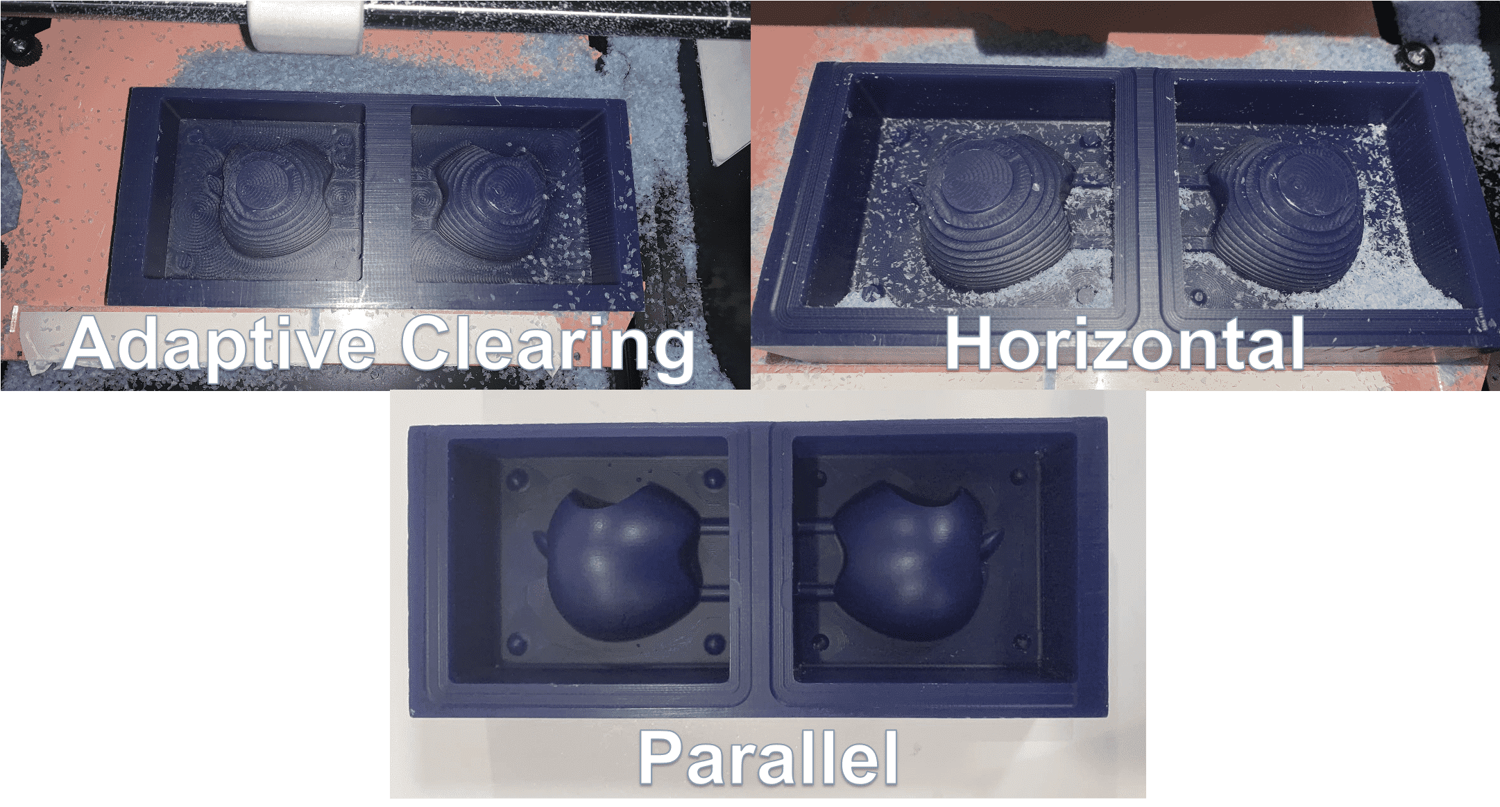
- Adaptive Clearing: used for clearing large quantities of material,cutting deep without the tool risk of breakage, which is why here the Bull-nose end mill is used.
- Horizontal: Automatically detects all the flat areas of the part and clears them with an offsetting path and machines in stages, Ball end mill is used here.
- Parallel:the final step here which is one of the most widely used finishing strategies, best suited for shallow areas and down milling, also the Ball end mill is used.
- Tool Properties: Where we will select the end mill type and change the feeds and speeds. Maximum Feedrate=1000 mm/min , Maximum Spindle Speed = 8500rpm.
- Geometry Properties: Where we will choose the stock contour and specify the model.
- Heights Properties
- Passes Properties: Where we will specify the Direction and mainly change the fine stepdown.
- Linking Properties
Now we can simulate and check for errors and also can see the machinning time for the whole process and for each individual process.
Milling
Milling process is the same as used in the Electronic Production Week. But before beginning, the files must be prepared and exported from Fusion 360.To do so, we right click on our setup (the 3 processes individually) and choose post process and select the machine and save it by the name to avoid confusion during the import.
Then we insert the required milling bit and set the machine coordinates and import the processes in correct order. During adaptive clearing, it is recommended to pause the process every now and then to clean/vacuum the wax residues and resume. The results are shown on the left, we can wash the stock after we are done from milling just to ensure there are no particles remaining inside.
Safety
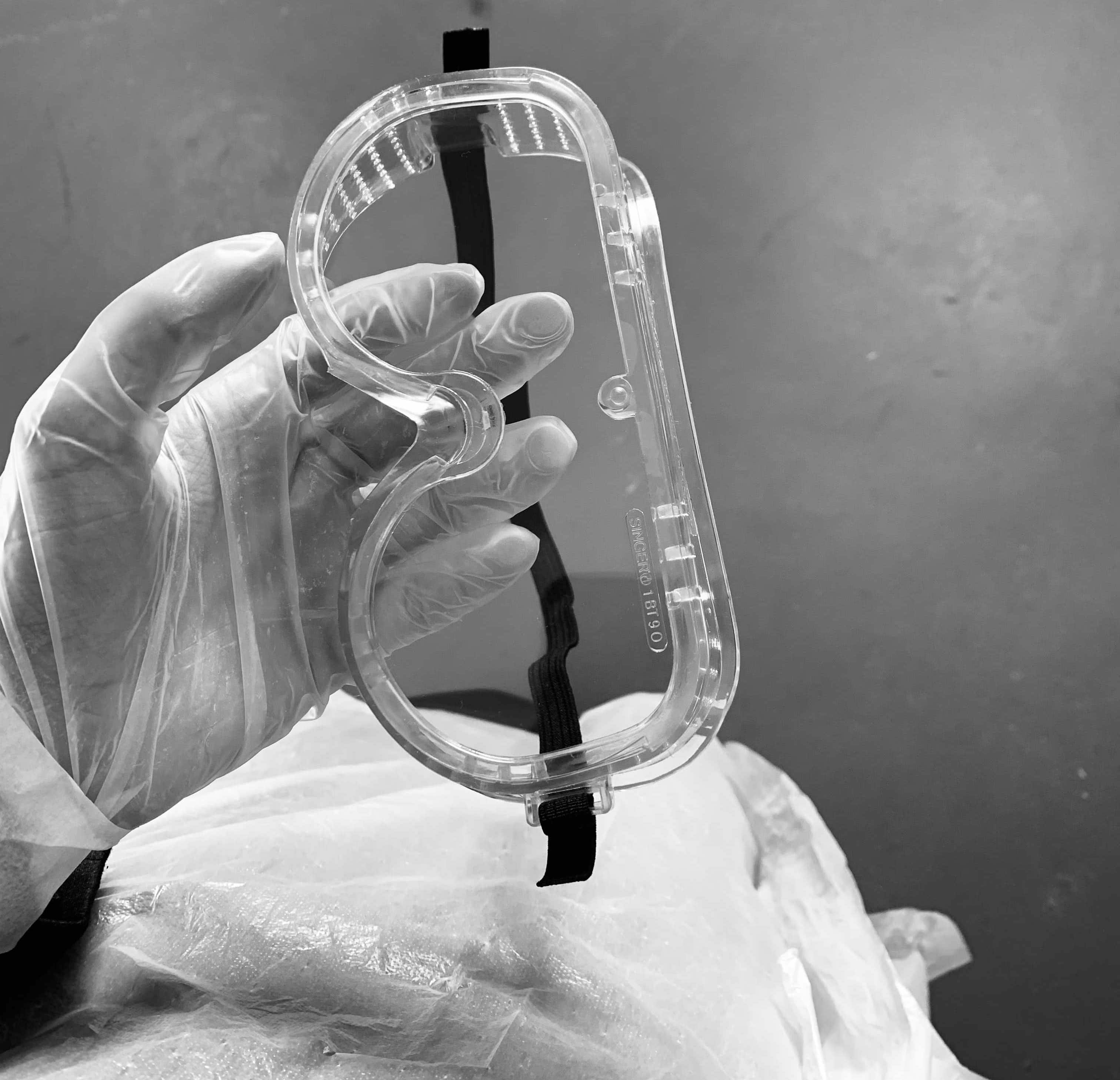
Before starting with the molding and casting process, we must make sure that we read all safety rules that are mentioned within the manuals since we will be dealing with materials that can be very harmful.
Goggles, Masks, Gloves and Safety Aprons should be worn all the time during the processes.
Molding
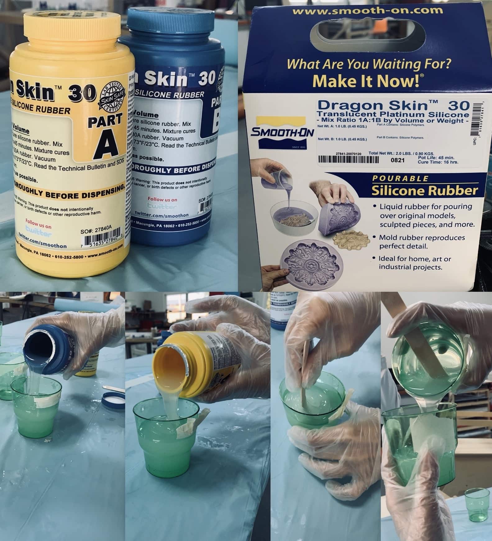
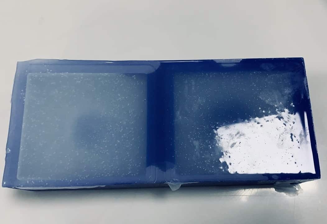
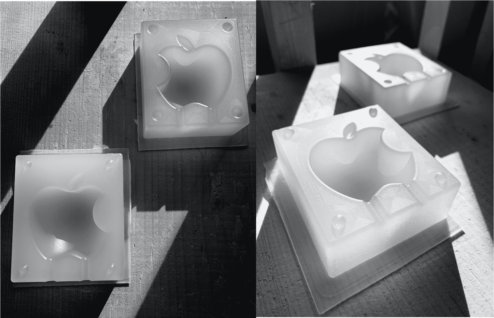
For the mold, i chose the Dragon Skin 30 , which are high performance platinum cure liquid silicone compounds, the full specifications and guidlines are found here. After reading the specs, we are now ready to start. Since the mix Ratio is specified as 1A:1B by volume or weight, so we just need to know the approximate amount needed to cover our design, this was done by filling the stock with water and knowing how many cups are required to fill and based on that we specify our quantity for the full stock.Pot time should be taking into consideration, but for this material it lasts for 45 minutes, which is longer than needed to finish my part. Starting by shaking both materials before pouring, we start pouring the material A and B seperately in cups with exact amounts, then mixing them for about a minute. After that we mix A & B in one cup with the same amounts, and mixing it for another minute. Then we pour it in stock slowly, making sure to pour from only one position until the stock is filled.As mentioned in the specifications, the curing time takes 16 hours. Results are shown on the left.
Casting
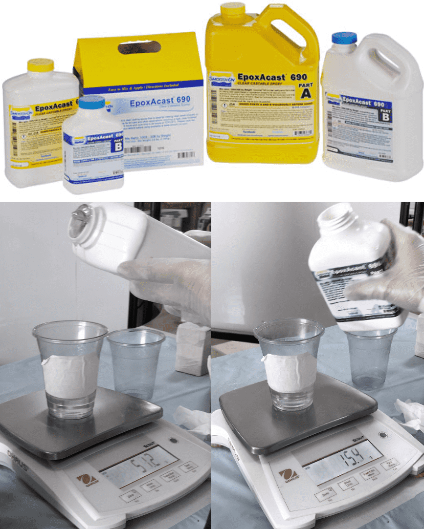
For the casting material, i chose the Epoxy EpoxAcast™ 690, which is a clear casting epoxy resin, a color can be also added since it is clear, it features a very low viscosity for easy mixing and minimal bubble appearances. The material specification and guidline are shown here.
Main characteristics of the material is that it is mixed 100A:30B by weight, working time is 5 hours and cure time is 24 hours at room temperature.
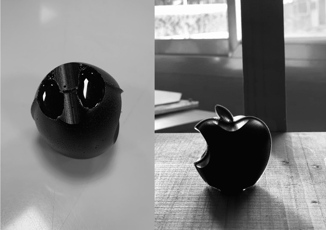
I began first by measuring how many cups of water it i'll need to inject the mold and filling it up, then the cups level were labeled to serve as guidline when using the epoxy. A material was poured and the weight was 51.2g, thus material B should weigh 15.4g. After pouring them, mixing starts and goes on for 1:30min, then the color is added by dipping the stick edge inside the color since just few drops are required, then we continue mixing for another 1:30min. Now we are ready to start the injecting process, before that, we make sure that we place a tape all over the mold to prevent any leaking during the injection. Then it was kept inside the room for 24 hours and the result is shown on the right.
I began first by measuring how many cups of water it i'll need to inject the mold and filling it up, then the cups level were labeled to serve as guidline when using the epoxy. A material was poured and the weight was 51.2g, thus material B should weigh 15.4g. After pouring them, mixing starts and goes on for 1:30min, then the color is added by dipping the stick edge inside the color since just few drops are required, then we continue mixing for another 1:30min. Now we are ready to start the injecting process, before that, we make sure that we place a tape all over the mold to prevent any leaking during the injection. Then it was kept inside the room for 24 hours and the result is shown on the right.
Group Assignment
For this task, we need to do the following:
Review the safety data sheets for each of your molding and casting materials
Make and compare test casts with each of them
The link to the group assignment page is found here.
Experience
A very lengthy week but intresting, it it is very long due to the several processes it needs to get the final result. It was my first time creating a mold and casting, in addition to CAM feature in Fusion 360 which was also new to me. I'm very glad that the results were good!