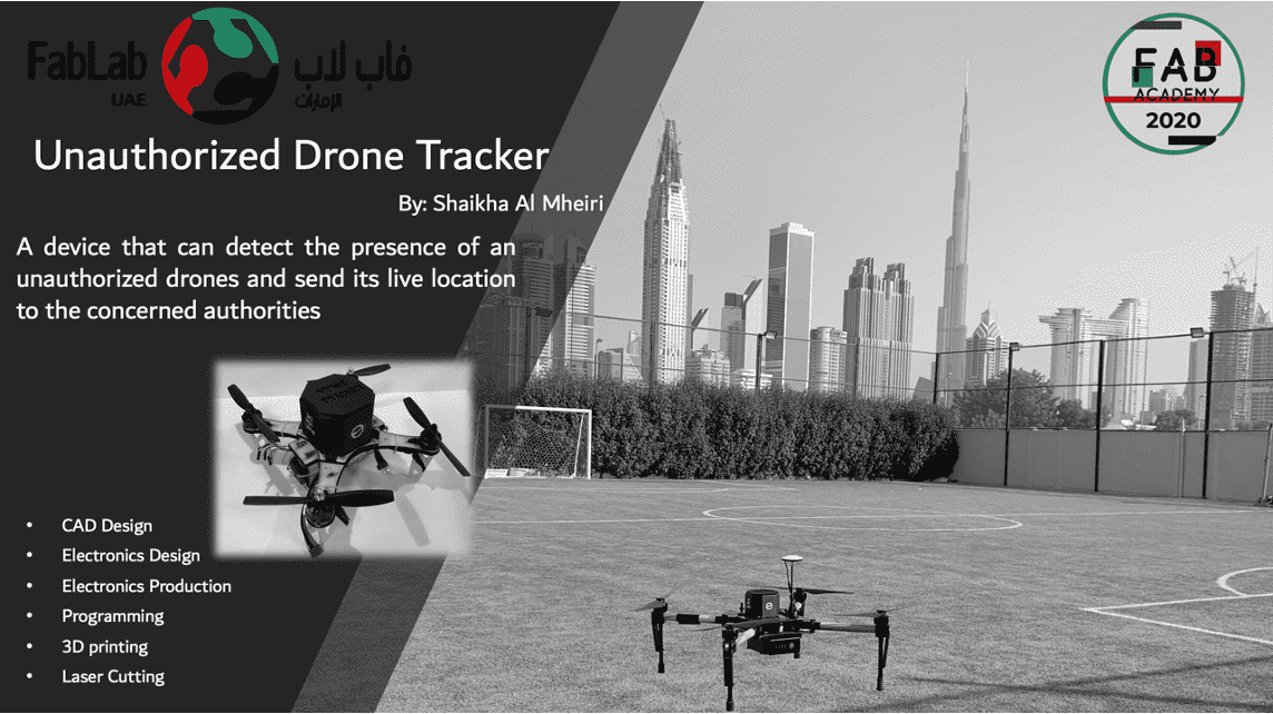
Initial Idea
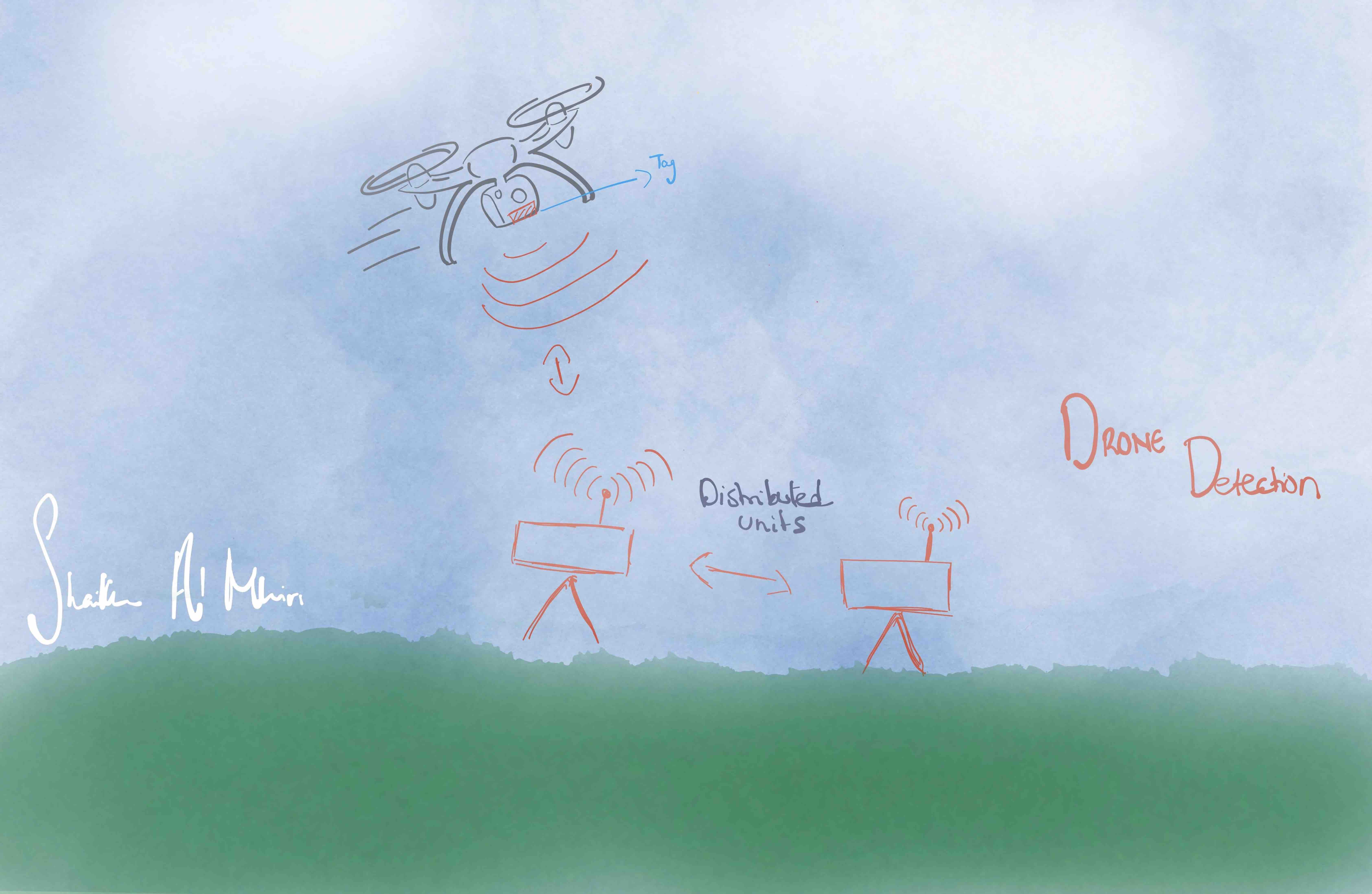
A device that can detect the presence of an unauthorized drones through distributing detection nodes all around the city to provide a full coverage for the area. In the UAE, we have General Civil Aviation Authority (GCAA) which applies regulations on flying drones and practising recreational aerial sports and activities. Some of the safety measures under the regulations are licensing and registration procedures, identification of no-flying zones, laying down rules for pilots flying the drones and penalties in case of violation and maintaining the airworthiness of the drones. The regulations aim to ensure safety in air and on land. It also aims at protecting user data and their privacy. Many users have wrong practices and unauthorized uses of the drones, thus the aim of having these nodes is to detect the drone ID and location and communicate with the local police to do the required action. This will be used by and limited to the military, police and first responders only, which will help to keep drones out of restricted airspace.
| Question | Answer |
|---|---|
| What will it do? | Detect drone flights that fly above the authorized level. |
| Who's done what beforehand? | Currently unauthorized flights are detected on spot. Authorization process includes signing up on form that contains route of the flight for limited duration only. |
| What did you design? | A piece that can be attached to drones that enter the country that will act as a tracker and communicate constantly to the authority station to report any unauthorized flights. The design was made based on on a fablab made drone satshacopter 250X and tried it also on one of the existing drones. |
| What materials & components were used? | For the electronics:
|
| Where did they come from? | Fablab |
| How much did they cost? | Almost all of the materials were found in the lab, some only were purchased through dealers and local markets.The following table shows a breakdown of the materials used and their unit price, note that the price is considered approximate since the lab buys the items in bulk amount and thus usually the unit price will cost way less than when it is bought individually.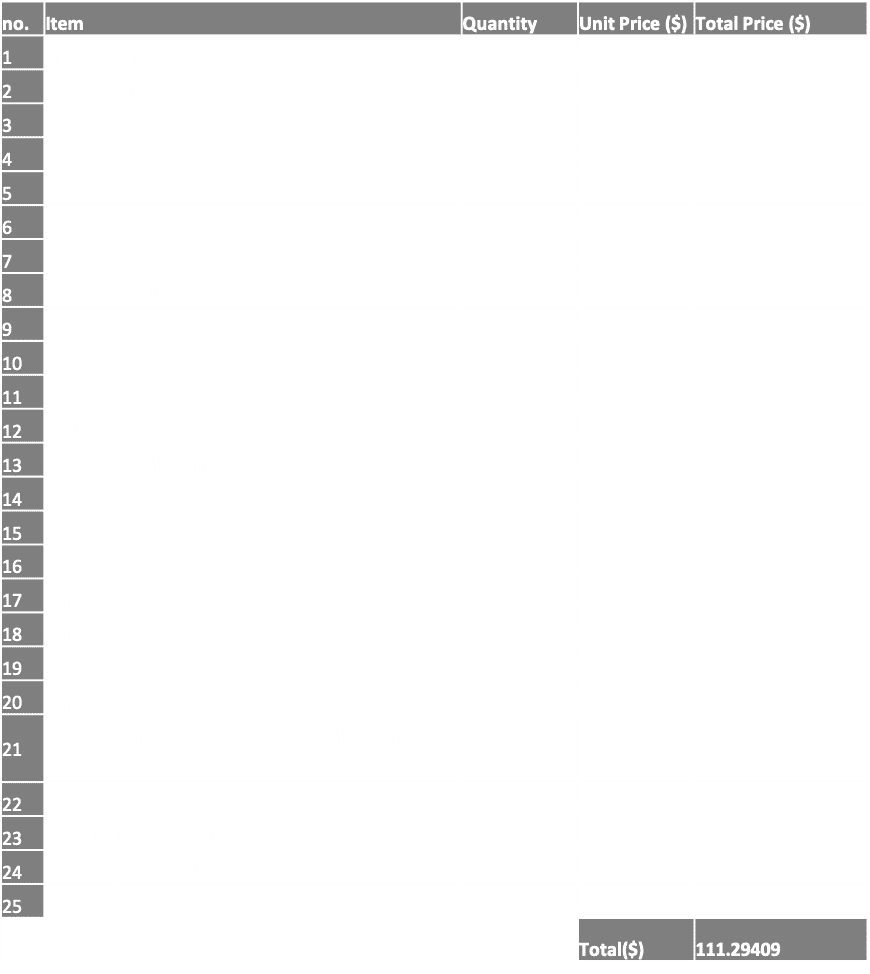 |
| What parts and systems were made? |
|
| What processes were used? |
|
| What questions were answered? | Throughout the project creation, I was able to answer the following questions that i asked in the previous weeks:
|
| What worked? What didn’t? | What worked:
|
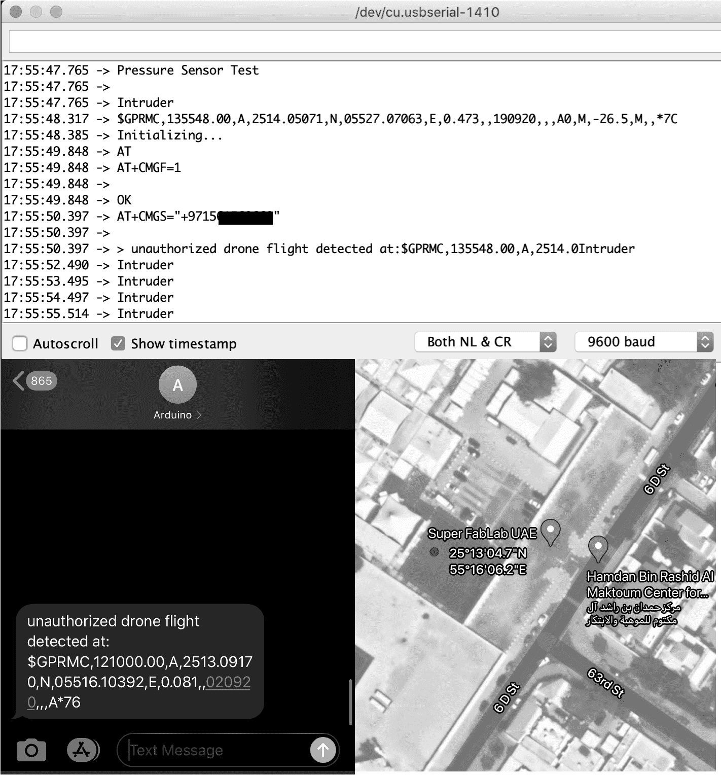
| How was it be evaluated? | When the device can detect unauthorized drone flights after it exceeds the authorized height and can communicate the coordinates of this drone to the receiver side (authority in real life). |
| What are the implications? | As mentioned before, the project is targeted to be used by and limited to the military, police, and first responders only. I am working currently with one of those sectors to submit and present the project idea on them and look into how we can proceed further, since currently detection methods happen only on site and there isn't a solution to detect public drones remotely unless they are near sensitive zones such as airports, jails, military and so. |
Fabrication Processes
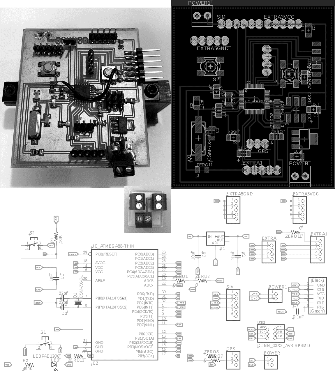
Electronic Design & Production
Downloads
Programming
- GPS GP-20U7: To send the coordinates of the drone after unauthorized detection to the control center.
- Sim Module IOT-GA6: To communicate the coordinates to the control center.
- Pressure Sensor BMP180: To detect the altitude above the sea level of the current city from the barometric pressure.
Downloads
Programming Code
#include <SoftwareSerial.h>
String inWord;
char inByte;
String data;
SoftwareSerial GPS_Serial(10, 11); // RX, TX 11 is not connected
SoftwareSerial mySerial(3, 2); // Rx & Tx is connected to SIM module Tx and Rx
#include "<Wire.h>"
#include <Adafruit_Sensor.h>
#include <Adafruit_BMP085_U.h>
Adafruit_BMP085_Unified bmp = Adafruit_BMP085_Unified(10085);
float seaLevelPressure = SENSORS_PRESSURE_SEALEVELHPA;
/* Calculating altitude with reasonable accuracy requires pressure, sea level pressure for the position at the moment the data is converted, as well as the ambient temperature in degress celcius. Usually the sea level hPa have a 'generic' value of 1013.25hPa can be used defined as "SENSORS PRESSURE SEALEVELHPA" from "Adafruit_Sensor.h" library, but this isn't ideal and will give variable results from one day to the next.A more accurate value can be taken from the local <a href="https://www.avmet.ae/omdb.aspx" ><b>Aviation Meteorology NCM</b></a> for UAE in my case.   */
void setup() {
  // Start the GPS module

 Serial.begin(9600);
  Serial.println("Pressure Sensor Test"); Serial.println("");

  /* Initialize the sensor */
 if(!bmp.begin())
  {
    /* There was a problem detecting the BMP085 ... check your connections */
    Serial.print("Ooops, no BMP085 detected ... Check your wiring or I2C ADDR!");
    while(1);
  }
    GPS_Serial.begin(9600);

}

void loop() {
  sensors_event_t event;

    if(bmp.pressureToAltitude(seaLevelPressure, event.pressure) >= 1){  // number 1 here is just a value used for test, but this should be chnaged with the maximum height the drone can fly to.
Serial.println("Intruder");
      delay(500);

  while (GPS_Serial.available() > 0) {
        inByte = GPS_Serial.read();
        if (inByte == '\n') {
// END OF LINE
 // check is data we want
 // you can change this to get any data line values
            if (inWord.startsWith("$GPRMC")) {
                // put data string in variable
                data = inWord;
                  Serial.println(data);
mySerial.begin(9600);
Serial.println("Initializing...");
delay(1000);
mySerial.println("AT"); //Handshaking with SIM
mySerial.println("AT+CMGF=1"); // Configuring TEXT mode
updateSerial();
mySerial.println("AT+CMGS=\"+ZZxxxxxxxxxxx\"");//change ZZ with country code and xxxxxxxxxxx with phone number to sms
updateSerial();
mySerial.print("unauthorized drone flight detected at:");
mySerial.print(data); //text content
updateSerial();
mySerial.write(char(26));

                // clear the inword variable
                inWord = "";
            } else {
                // clear the inword variable as not the data we want
                inWord = "";
            }

        } else {
            // build data string
            inWord += inByte;
        }

    } // end if serial

    }
    else{
    Serial.println("good");


    }

      delay(500);

    }

void updateSerial()
{
  delay(500);
  while (Serial.available())
  {
    mySerial.write(Serial.read());//Forward what Serial received to Software Serial Port
  }
  while(mySerial.available())
  {
    Serial.write(mySerial.read());//Forward what Software Serial received to Serial Port
  }
}
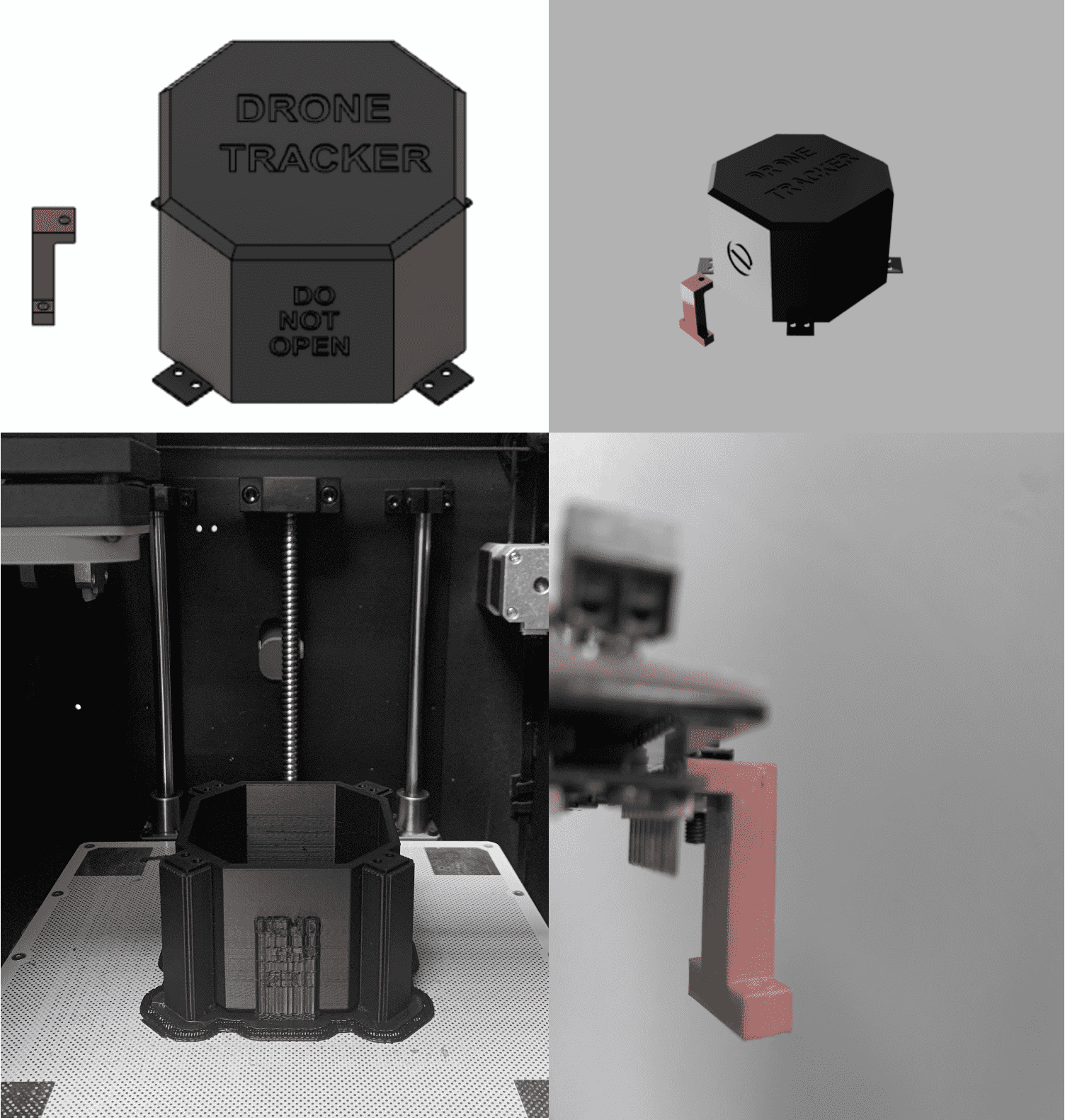
3D Printing
- Zortax M200 printer & Z-suite software were used for the main enclosure
- Ultimaker printer and Cura software were used for the internal leg structure
Downloads
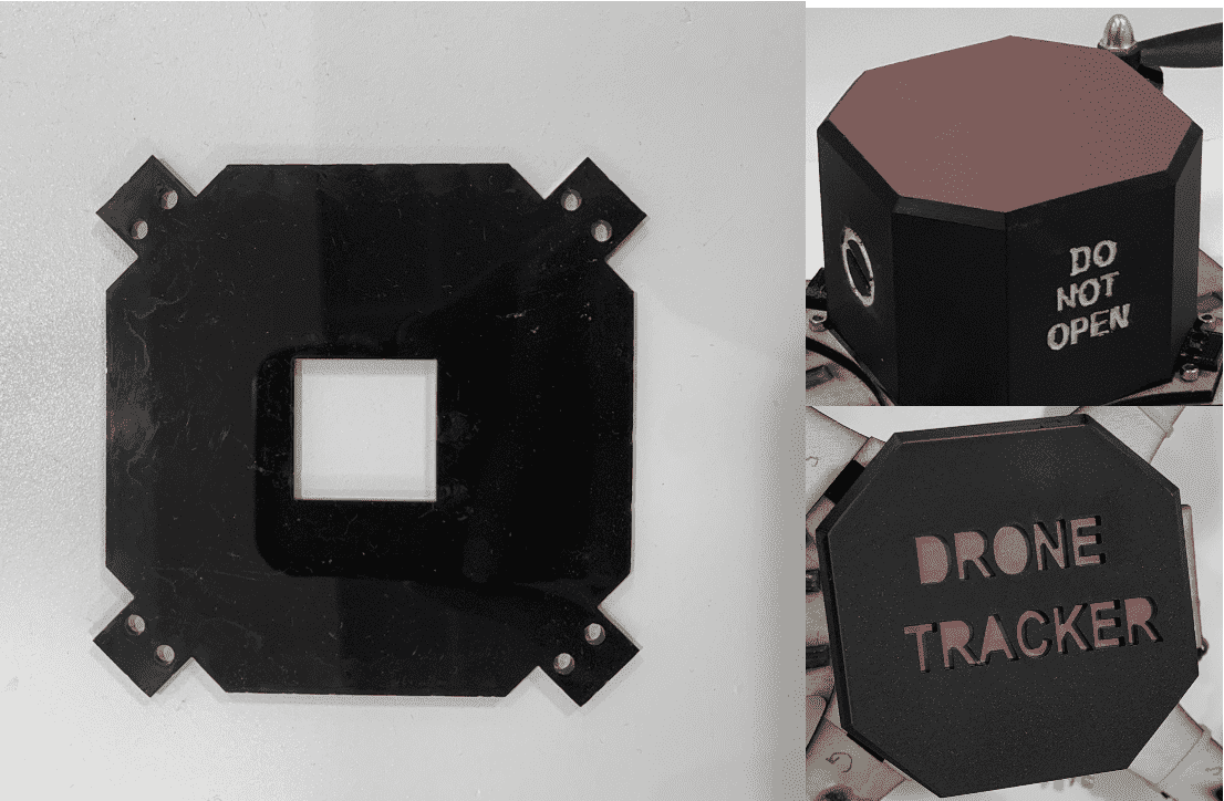
Computer Controlled Cutting
I also used Roland to cut vinyl sticker in red color and to place it on the upper side of the 3D just to give an option for an alerting color for the enclosure.
Downloads
Future Improvements
- To explore other network communication methods that consume less current and size-wise smaller.
- To explore other GPS modules that displays the information while connected to the RX or software serial ports which can be readible and user friendly.
- To look onto several methods of connecting the devices and show them on a map such as google map, to allow live streaming and that can be easy to target and track and follow up for the authority control center.
- To look for more sustainable options for the battery for longitivity and to track the levels in case power went off.
- Drone ID should be linked to the user ID to impose penalties in case of violation.
- To explore vandal proof materials for the enclosure and to send an alert in case someone tries to open it.
Presentation & Video