Assignment Objectives:
Design a machine that includes mechanism + actuation + automation.
Build the mechanical parts and operate it manually.
Actuate and automate our machine.
Instructor: Hashim Al Sakkaf
| Students | |
|---|---|
| 1 | Maha Al Hashmi |
| 2 | Ali Bin Ghulaita |
| 3 | Waleed Alhamdi |
| 4 | Shaikha Almazaina |
| 5 | Shamma Alqaydi |
| 6 | Fatima Al Hashmi |
| Mechanical parts | Students |
|---|---|
| X axis | Harib + Waleed |
| Y-axis | Maha + Shamma |
| Rotating base | Fatima + Shaikha |
| End effector + Wheels | Ali |
Preliminary Sketch:
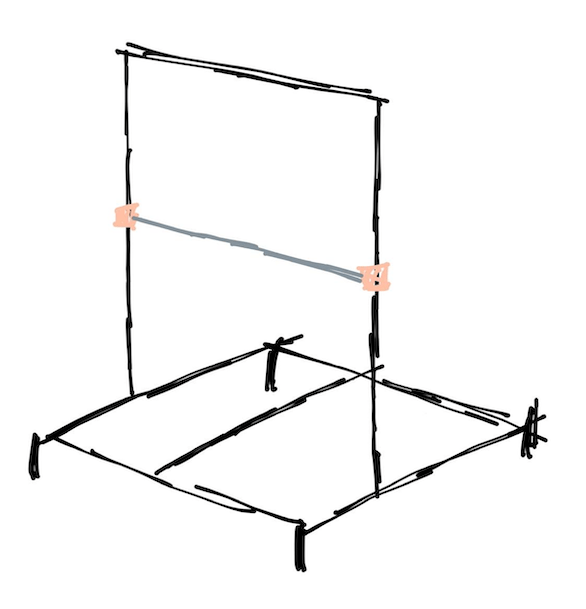
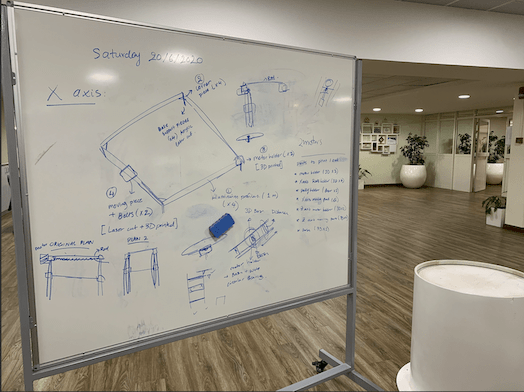
(suggested: 1 m x 1m x 1m)(suggestions: pressfit corners, screws, 3D printed joints, movement guides)(plastic case, arc ..etc)(suggestions: thread, belts, gears)(suggestions: Y-axis is attached to the X axis rail / Base is independent)(suggestions: direct power jack + power converter?)(Arduino , CNC shield)| Qty | Description |
|---|---|
| 6 | 40 x 80 Aluminum profile |
| 5 | Stainless Steel Rod, 1m |
| 3 | Stepper motor NEMA34 |
| 2 | Stepper motor NEMA17 |
| 8 | Pulley Wheel with Bearings |
| 8 | Aluminum Alloy Timing Pulley |
| 1 | Timing Belt |
| 4 | Linear Ball Bearings 12mm |
| 1 | Hot wire Fishing steel wire |
| 4 | Alligator Clips Electrical |
| 1 | CNC shield |
| 2 | limit switch |
| 1 | Power supply |
| - | Screw and nuts |
1. The frame ( X-axis & Y-axis):
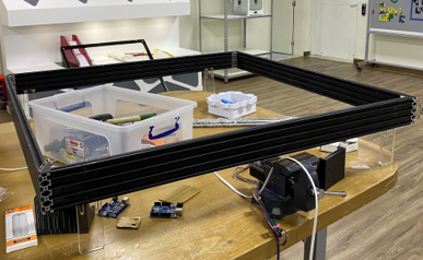
The frame:
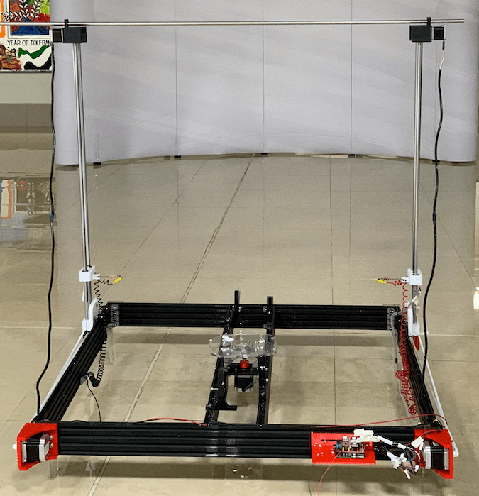
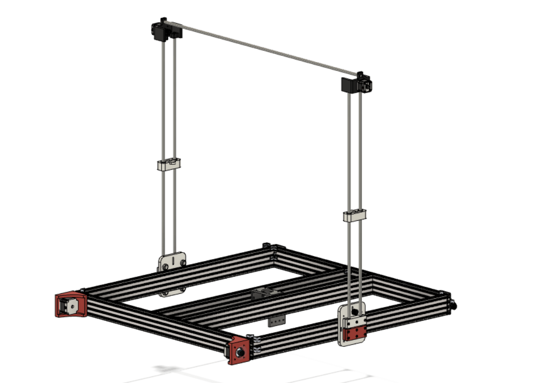
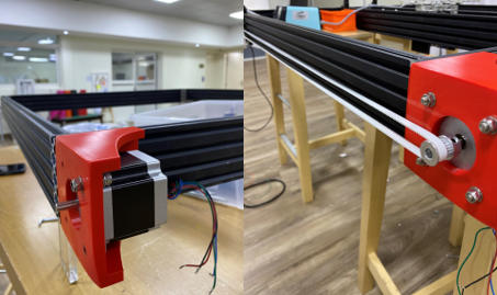
We chose to make the frame of the CNC foam cutter out of aluminum profiles. This was a quick (and seemingly wise) decision with regards to the time we have to build the machine. Aluminum profiles are strong enough to hold the Y axis, can be used to align the movement of the X axis properly, and are easy to build and align using corner pieces. Previously, we used 20x40 mm aluminum profiles to hold the structure, however due to the large scale of the machine in hand we chose to change the size to 20x80 mm to create a stronger frame.
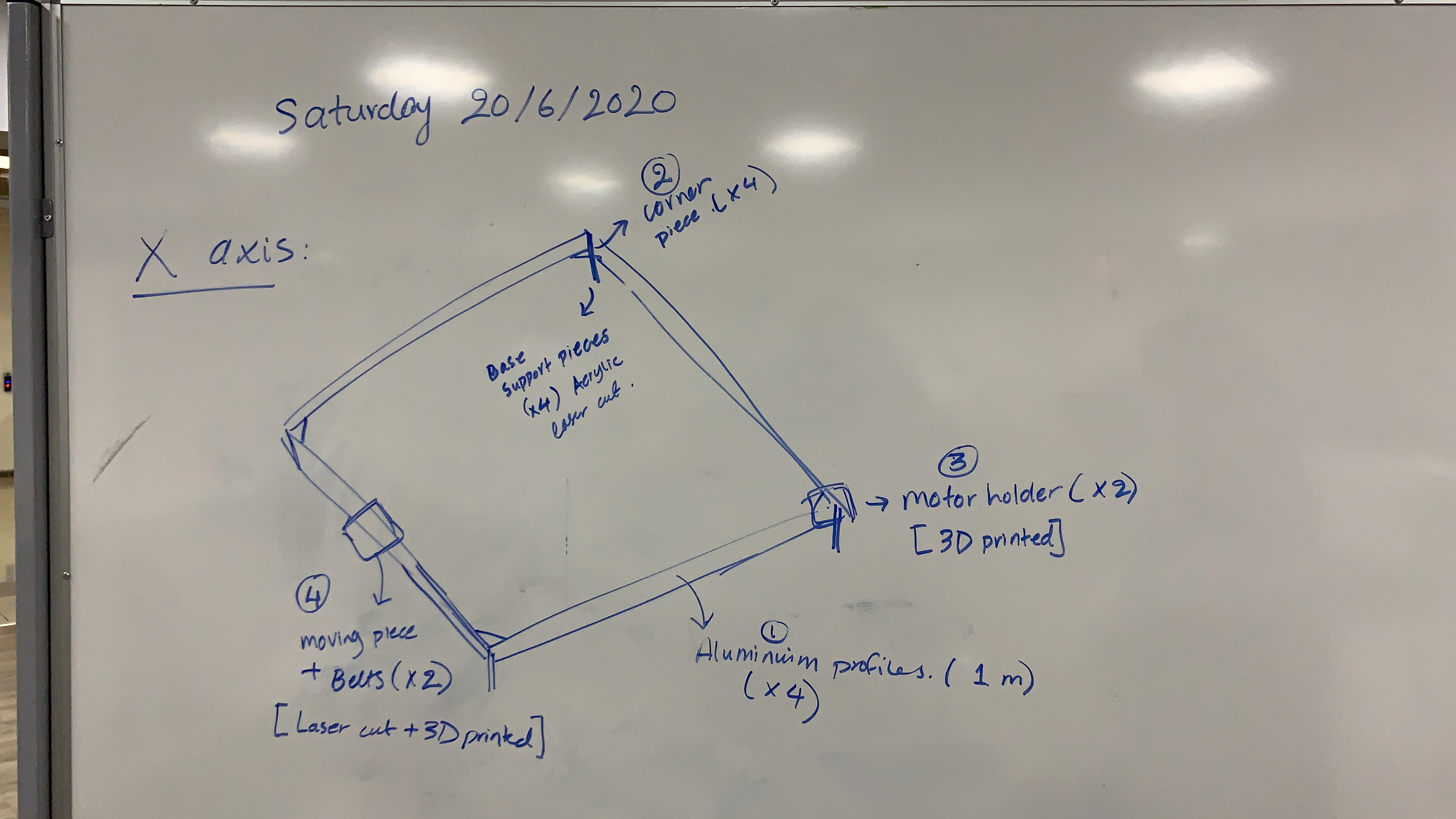
X-axis:
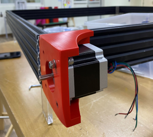
The design parts of the X axis include two motor holders that fit at one end of each of the two aluminum profiles used for the X axis. The pieces were designed and 3D printed so it can fit a Nema 34 stepper motor and a pulley, and can be attached to the aluminum profiles using screws. Furthermore, a 12 mm laser cut Acrylic piece is fit at the other side of the x-axis to hold the second pully used to move the timing belt. The final part is the piece that would move along the X axis, and will hold the Y axis (alignment rods, timing belt and moving pieces), the piece is designed to fit on the aluminum profile and move using wheels on the top and bottom edges, we made the pieces by cutting HPDE material using the CNC machine, and attach 3D printed parts to hold the Y axis alignment rods.
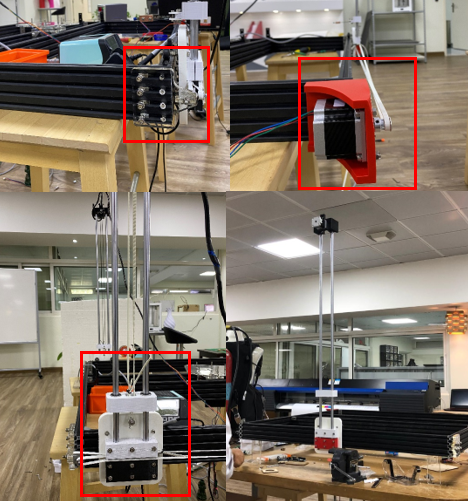
Y-axis:
The Y axis consists of four parts: two metal alignment rods (each 1 meter in height), 3D printed pieces that move along the rods (using linear bearings) and hold the end effector, 3D printed enclosures that hold two Nema 17 motors at the top of the metal rods, and an extra metal rod that holds the enclosures together for a better alignment.
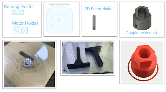
We design different pieces on fusion. The first piece that we designed was motor holder. since we will use NEMA 34 we made our design based on NEMA 34 dimensions and its shown in the below picture.
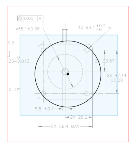
We tested the design using MDF on laser cutting machine to check if the size is fit or not to start print it using 3D printer which will take a lot of time to finish the holder. then we had to attached the NEMA 34 to the holder, and, attached it to the aluminum profile (20mmx80mm) in both sided and make sure that they are aligned. On the opposite side of the machine we insert the two idler pulley.
so now we are ready to install the GT2 belts for the X axis. First, we inserted and secured the belt to the sliding block. Then we passed the belt around the tooth pulley, on the other side around the idler pulley, cut it to the appropriate size and again secured it to the other side of the sliding block.
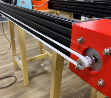
We repeated this process for the other side as well. When securing the other side, we must make sure that the two sliding blocks are on the same position on the X axis. For that purpose, we can simply move them to the end of the rails and so we can tighten the belt and secure. With this the X axis sliding mechanism is done.
2. Rotating axis:
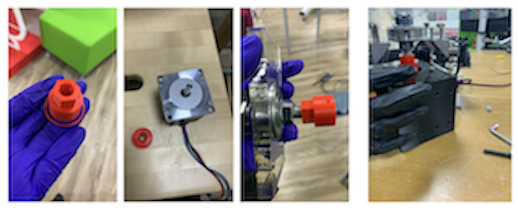
The rotating axis is held by two aluminum profiles fit in the frame, with a 3D printed motor enclosure on the middle to hold the Nema 34 motor used. A 3D printed coupler is used to connect the motor shaft to the circular bearing fit under the 12 mm laser cut Acrylic sheet.
The initial concept was to have a 3D printed rotating base that fits into the motor shaft. And the part is attached to one aluminum profile 20x40cm using 3D printed joint.
The concept evolved in several stages. The aluminum profile size was changed to 20x80cm and the quantity to 2 pieces of the profile in which the rotating base will be attached in the center of both.
3. End Effector:
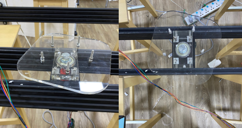
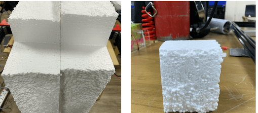
For the hot wire, we used the same wires used in fishing which is made with steel. They can get really hot when current flows through it.
For the hot wire connection, each spring is connected to the copper board with a small plastic part for insulation. Moreover, the springs are connected in the movable part of the Y-axis.
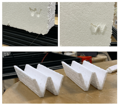
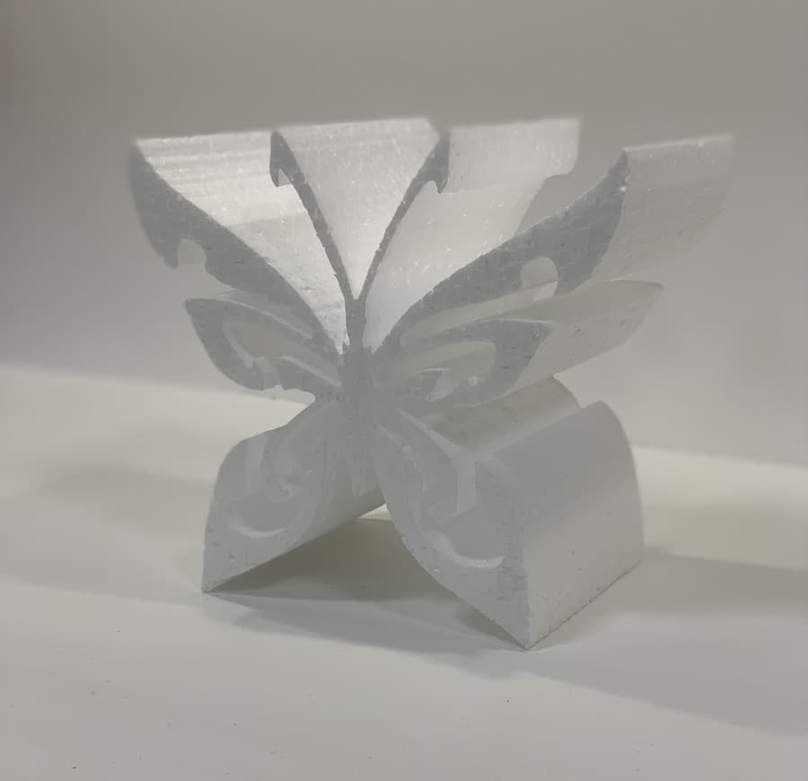
For supplying the power, we connected each end of the hot wire through alligator clips, the needed voltage around 23 V DC to cut through the foam without resistance and bending.
Hot wire test:
First, we started by joining the aluminum rods to create the frame, we used corner pieces to ensure 90 degree alignment between the pieces.
Next we attached the motor holder using screws and mounted the Nema 34 stepper motor inside, securing the motor with screws. We also connected the pully holder on the other end of the X axis to attach the timing belt eventually.
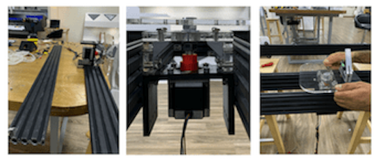
We tested the X axis moving piece on the aluminum rail to ensure accurate dimensions and smooth movement. Once the dimensions were set and clear we cut the HPDE material using the CNC machine we had in the lab, and attached the two 3D printed parts to hold the 12 mm alignment rods for the Y axis.
Then we were ready to install the GT2 belts for the X axis. First, we inserted and secured the belt to the sliding block. Then we passed the belt around the tooth pulley, on the other side around the idler pulley, cut it to the appropriate size and again secured it to the other side of the sliding block.
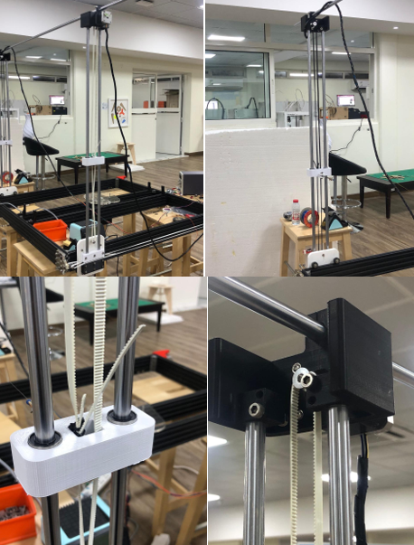
Once we checked the movement of the HDPE pieces, we attached the 1 meter (12 mm) metal rods that will be used to align the timing belt in the Y axis. We inserted the 3D printed moving piece and the 3D printed holding piece at the top, along with the top alignment rod. Then finally, we added the timing belt and secured them using zip ties.
for the rotating base, At the beginning we 3D printed a coupler to be attached to the shaft of the motor and then to the base, to ensure the rotation. Since we didn’t want the full load of the rotating base to be held by the motor, we chose to insert bearings to assist the motor’s rotation and to rotate smoothly. So we first thought of extending the support of the base to be inserted inside the base all the way to the coupler. But, 3D printed parts can sometimes be hard to predict and accuracy might not be met. Thus to have a more rigid structure, we decided to insert a bolt M12 in the middle of the rotating bases and to be extended all the way to the shaft. Nuts were used to tighten the structure. For the bolt and shaft to meet, we designed a coupler with spiral head to fit into the bolt and cylindrical shape from the bottom to fit the shaft. This was the final design of the structure, the holder was design based on that where the bearing was fit into the acrylic board and attached to both profiles, the motor holder was also attached to the aluminum profile but separate from the bearing to make sure load isn’t combined on the motor itself.
This was one of the toughest phases through making the hot wire foam cutter this due to the countless problems and challenges we have to go through to solve the Problems…
We used the Arduino UNO as out main microcontroller along with the CNC v3 shield which uses open-source firmware on Arduino to control 4 stepper motors using 4 A4988 Stepper drivers,, with this shield and the Arduino you can build all kinds of robotics or CNC projects including CNC routers, laser cutters and even pick&place machines.
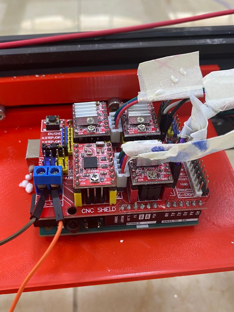
As its seen from the above picture that the CNC shield got only four stepper motors to connect to, but in our machine we have 5 stepper motors where we have 2 motors in the z y axis, 2 motors in the X axis and one in rotating base which we call it the Y-axis in our case, to solve this issue we decided to connect the Y axis motor together in parallel and both of them will receive the same signal from the CNC shield from the Y stepper motor drive, due to the fact that The shield supports a fourth “A Axis” driver which may be configured using jumpers to mirror any of X, Y, or Z. We connected the other X axis motor to the “A axis” driver to mirror the X driver.
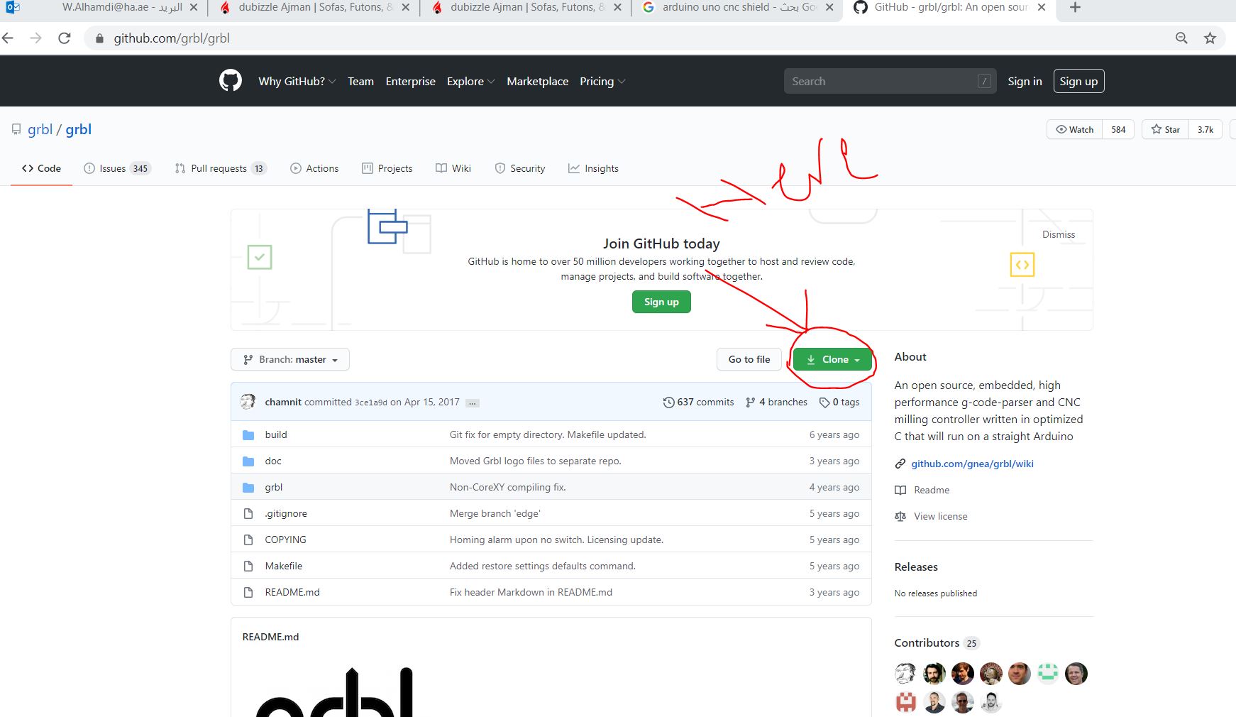
Grbl is a no-compromise, high performance, low cost alternative to parallel-port-based motion control for CNC milling. It will run on a vanilla Arduino as long as it sports an Atmega 328 you could easily download the library and add it to the arduino this is done by the following:
1- Download the Library from the LINK
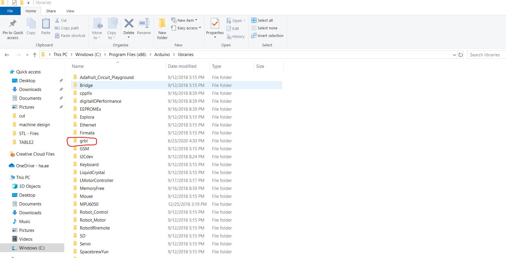
2- Extrac the file and add the file to the Arduino library
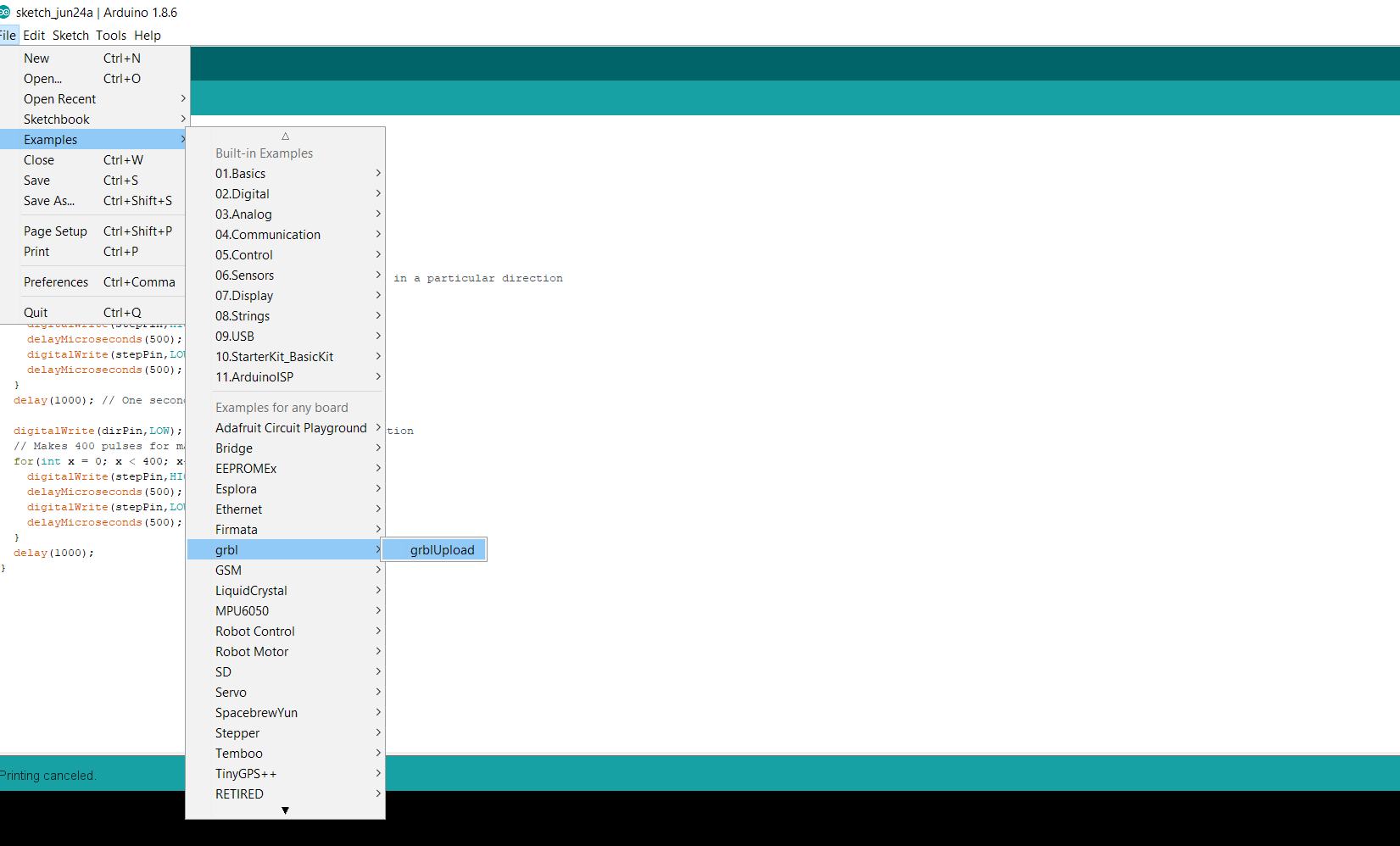
3- Open the Arduino IDE and upload the grblupload example to make the Arduino ready.
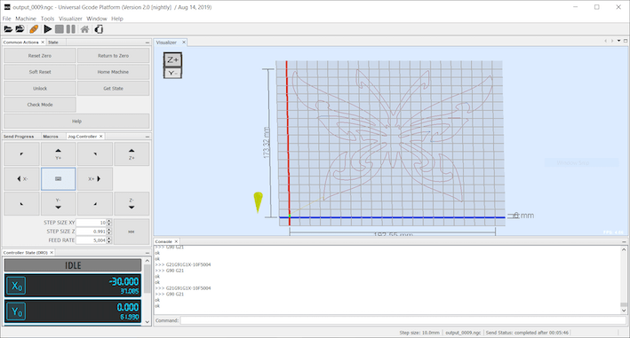
UGS stands for Univeral Gcode Sender which is used for interfacing with the CNC controllers in this case is the GRBL which can be downloaded from the following LINK
Manual:
Automatic:
We have to test the design using MDF first to not waste material since the acrylic is expensive. We did many trials to find the fit size of the pieces. Also we spent a lot of time on searching for the screws, the place was in mess and there wasn’t enough tools.
It was hard to insert the limit switch because we need to make sure it touches the axis while moving, also the area was too small to lay the switch on the aluminum profile.
The structure part to the Y-axis (motor holder) the holes was very small so we used force to insert the screws into the holes.
We used the drilling tool to fix the sizes of the holes in some 3D printed parts to fit the screws in.
It was hard to attached the rotation base because we made the alignment first so the space was very tide so the movements was difficult.
It was hard to attach the rotation base to the machine frame because we need to do the alignment first, then assemble the rotating base in the aluminum profiles. Thus the space was very tight so the movement was difficult, which led us take a lot of time fixing it.
These are the combined suggestions of how can we improve the machine we built for the future:
Add the limit switches to calibrate the origins and the distances accurately.
Fix the rotating base so it is not wiggly during movements and can handle a good load.
Add wheels to the machine, so it is easily transferable.
Fix the 2D holder so it can be adjustable to different sizes of foam of different widths.
Add a user interface (a touch screen for example), so the design can be directly inserted with an SD cad or through WIFI, and to calibrate the origin points the heat level of the hot wire easily.
Create an enclosure for the machine for safely purposes (hot wire!) and for easy cleaning. The enclosure can be made in transparent acrylic so we can keep an eye on the progress of the machine. As well as a base on the bottom of the enclosure to collect all the excess foam from cutting.
A sensor can be added to the door of the enclosure to prevent the machine from starting if the door is not shut (for safety measures).
Use a single plug in source for powering the motors and the hotwire together, instead of the power supply.
Use aluminum profiles on the top of the structure to create a rigid parallel movement of the X axis.
02/06/2020 - 04/06/2020:
Abu Dhabi is in lockdown again! unfortunately this means that our instructor Hashim is unable to come to the lab, Thus the work is halted.
07/06/2020:
Lockdown in Abu Dhabi is extended.
20/06/2020:
02/06/2020 - 04/06/2020:
In 02/06/2020 Tuesday: Some of the in cities in UAE had lockdown again. Sadly, some students and our instructor were living there.
So, we had to stop working in the machine until they come back because we need lab access and to work as a group together. we tried our best by doing online classes and meetings.
07/06/2020 Sunday:
The lockdown was supposed to be only one week but had extended to one more week, so we decided we need to continue because there is no enough time. We had a group meeting to discuss the design of each part in the machine, also we created a project in the fusion 360 cloud, so we can work together in the CAD design of the machine.
25/06/2020 Thursday
CNC foam cutter