For the group assignment, we cut some test parts with different feeds and speeds using the Shopbot.
We used a 6 mm plywood mill bit to cut the pieces, but unfortunately, the spindle was not running, and the tool broke instantly. 😨
Thankfully, no body got hurt, but we were defiantly surprised, and shocked!
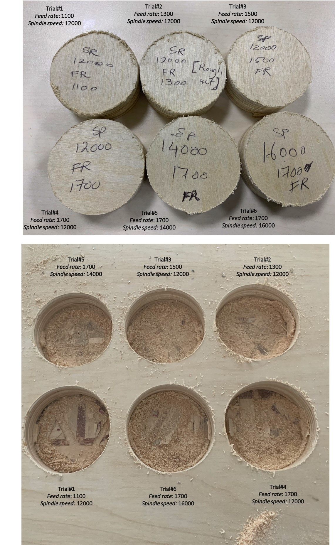
We switched to the 3mm plywood mill bit, and we tested the feeds and speeds by cutting 50 mm circles on an 18 mm wood sheet. We first lowered the feed rates gradually, while keeping the spindle speed constant at 12000, then we changed the spindle speed while keeping the feed rate at 1700.
Here are he feeds and speeds we used along with the machining time:
| Trial No. | Spindle speed (RPM) | Feed rate (m/min | Machining time (min) |
|---|---|---|---|
| 1 | 12000 | 1100 | 3:14 |
| 2 | 12000 | 1300 | 2:45 |
| 3 | 12000 | 1500 | 2:24 |
| 4 | 12000 | 1700 | 2:09 |
| 5 | 14000 | 1700 | 2:08 |
| 6 | 16000 | 1700 | 2:09 |
Results:
As shown from the table, the highest machining time belong to trial #1, where we had the smallest feed rate, and the lowest machining time is in trial #5.
We observed that lowering the feed rate resulted in unclean sides, and slight burn marks.
The difference between the pieces is not very significant, as we didn’t vary the speeds and feeds by a large rate. But from what we observed, we think that the best finishing belonged to trial #4, which actually were the default settings of the 3 mm mill bit. The surface was smooth and the sides were cleaner than the rest, and it didn’t leave any burn marks on the wood.
For our second trial, we got a new 6 mm mill bit and we used it to test the feeds and speeds. This time we kept the spindle speed constant, and we changed the feed rate.
| Trial No. | Spindle speed (RPM) | Feed rate (m/min | Machining time (min) |
|---|---|---|---|
| 1 | 12000 | 1500 | 1:16 |
| 2 | 12000 | 2000 | 0:58 |
| 3 | 12000 | 2500 | 0.47 |
| 3 | 12000 | 3000 | 0.40 |
Result:
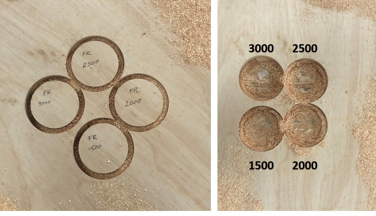
The finishing of the 2nd test was good.. We didn’t notice a huge difference in the finishing between the trials and thus we concluded that feed rate affects the time and not greatly on the finishing, the higher the feed rate, the less time it takes to finish, but all in all the results are very similar to each other.
For each of our objects, we tested the clearance to fit out pieces together. Here’s a summary of what each student did:
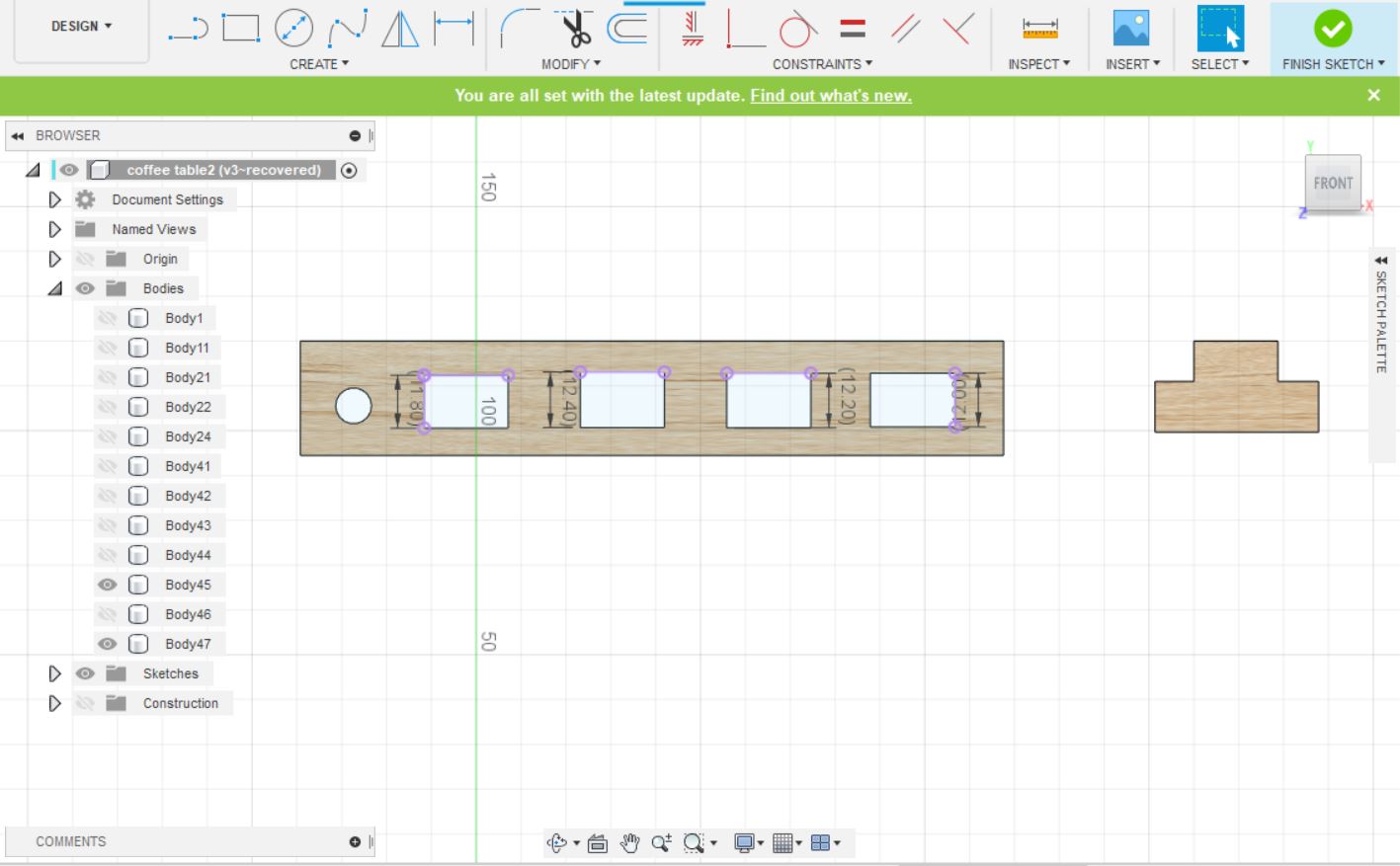
To test the clearance, I created a simple design with slots that varied 0.2 mm in width to see which would fit the best.
![]()
I milled the pieces and tested for the clearance value which came to be sheet width + 0.2 mm.
![]()
I created different joints sizes to test the best slot size that will fit my design
 the slots width difference was 2mm from each other
![]()