This week’s objectives:
3D printer : Ultimaker 3 extended.
Material : PLA.
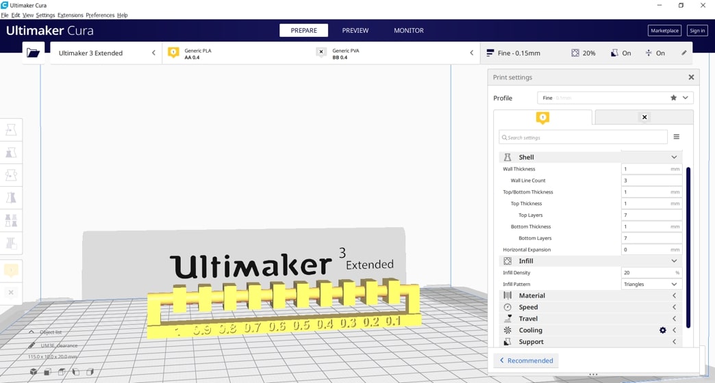
This design rule test aims to explore the minimal clearance or tolerance of the 3D printer. The test is done by fitting boxes with a hole in the middle , on a shaft, each hole is decreased in diameter by 0.1 mm. The boxes are expected to rotate around the shaft if the clearance distance allows.
I downloaded the STL file directly from the 3D scanning and printing page of the Fab Academy website.
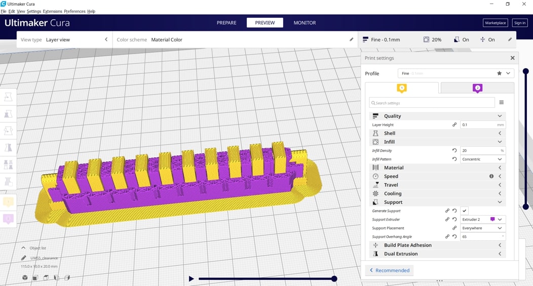
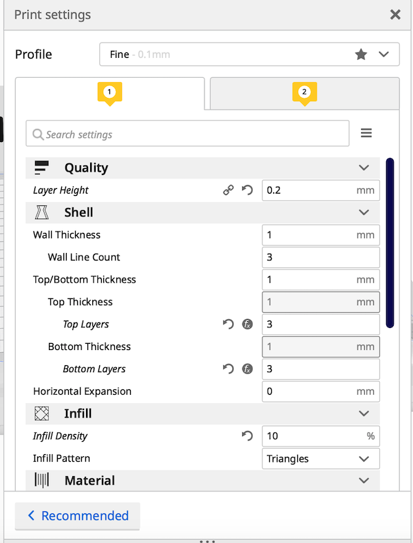
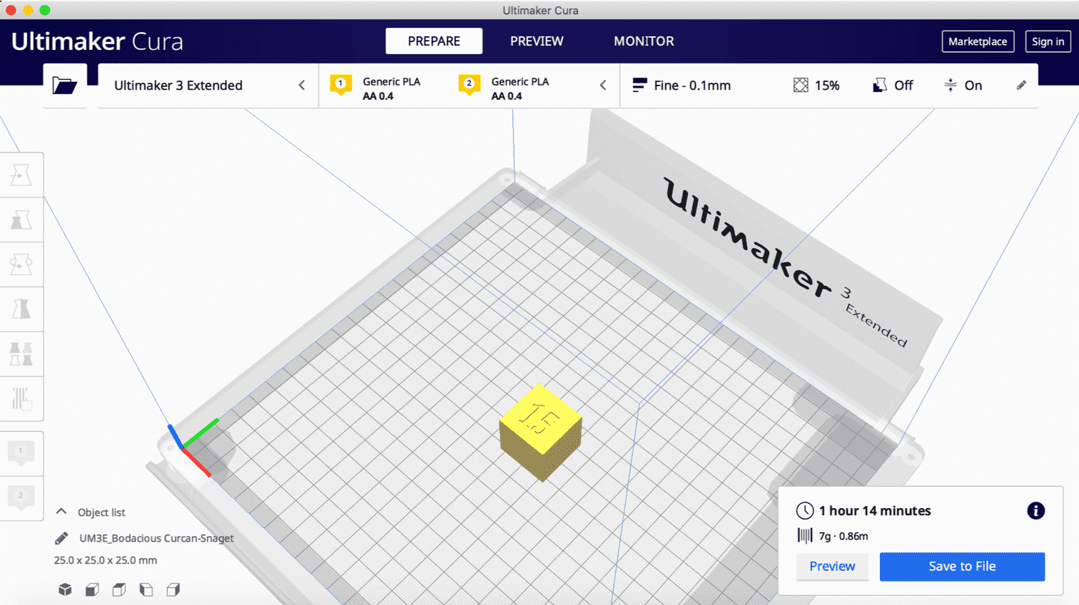
The next step was to slice it using Cura. The general values I used are the following:
The print duration was calculated to be 1 hour 59 minutes.
After saving the file on my flash drive, I headed to the Ultimaker 3D printer extended to start printing. I loaded the material I am using, calibrated the build plate, and then inserted the flash drive and initiated the printing process [note: The detailed process of the steps mentioned are in my personal page].
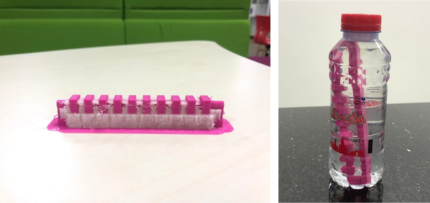
On the first attempt for the test, I forgot to add support to the design. Consequently, aborting the print midway and ending up with this:
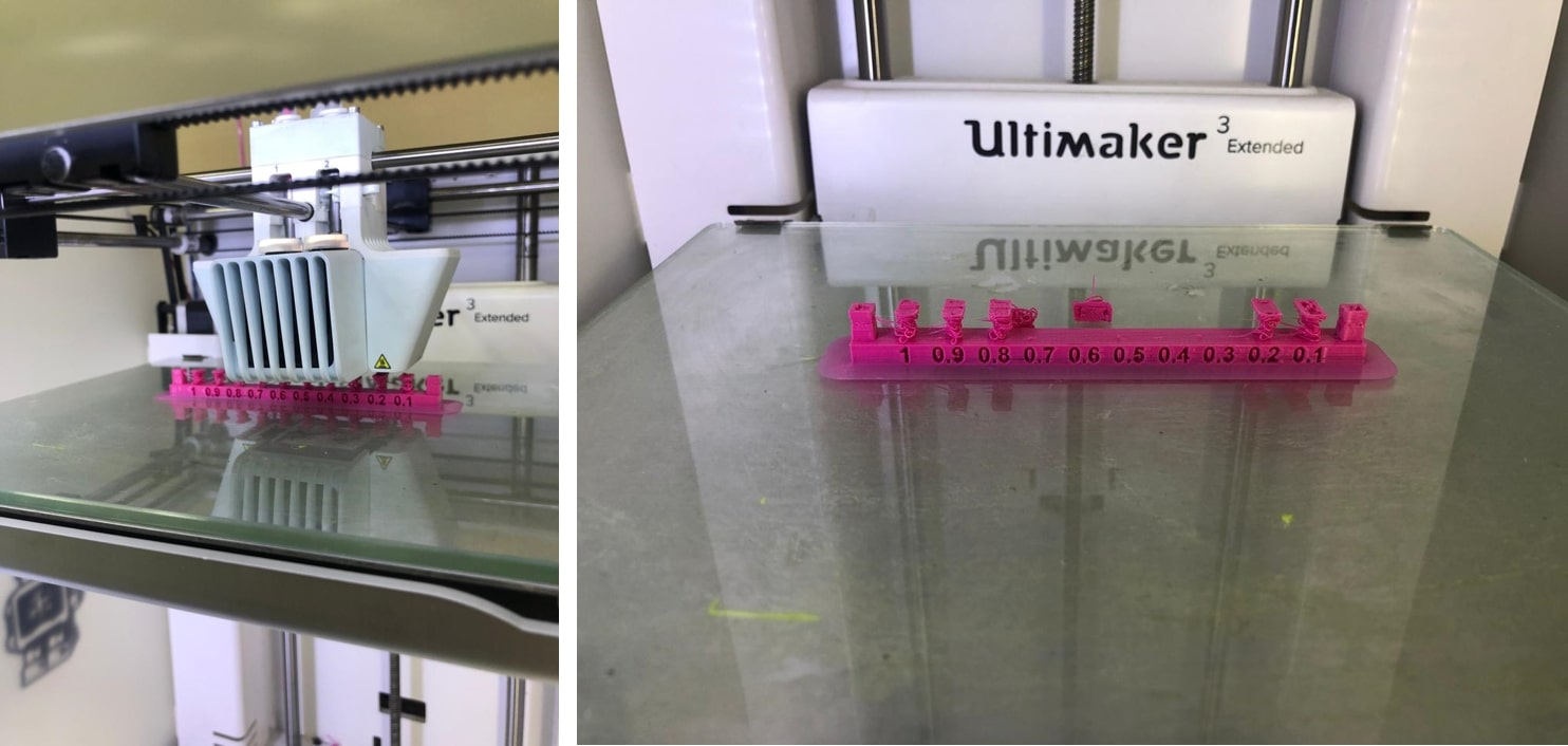
Since support was not initially added, the printer attempted to create it’s own by adding material and printing the rest of the design on top. This wasn’t very efficient, as it wasn’t enough to stabilize the piece on top and it ended up wobbling and breaking off.
Hence my experience with Cura and 3d printing was very limited, I sought some assistance and guidance from one of the former students of fab academy who (Lucky for me) was available at the moment. For my second attempt, I kept the general values the same as the previous attempt and added support.
There are two types of support that I could have used, A support using the same material PLA or an external support using PVA (Polyvinyl alcohol ) which is a water-soluble synthetic polymer. I went with the PVA hence it would provide better final results for the design tested.
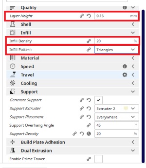
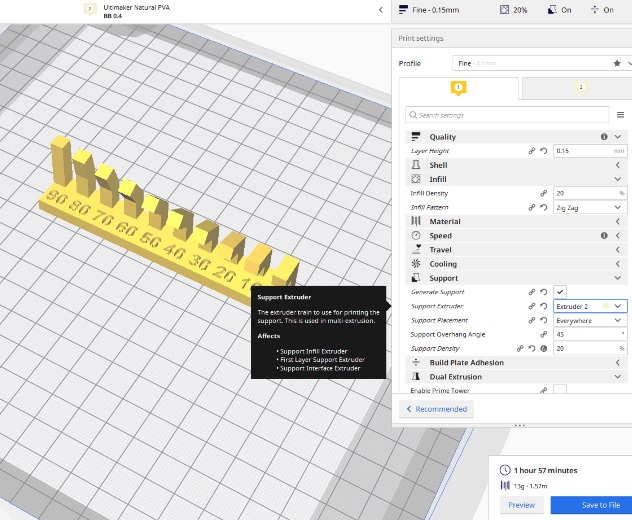
The support values I used are the following:
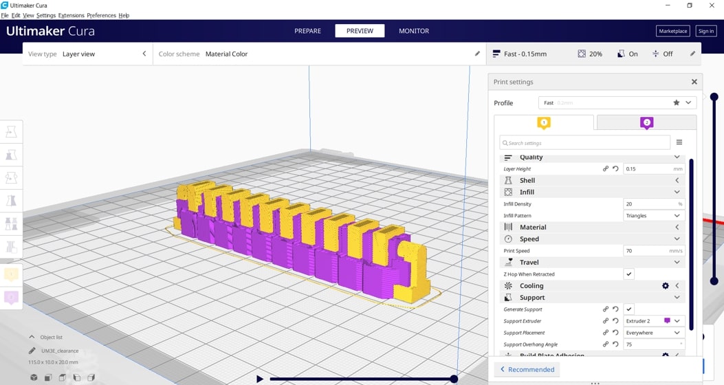
The print duration this time was about 3 hours and 30 minutes.
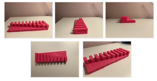
The results:
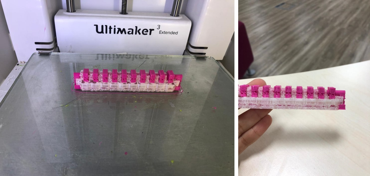
This piece was not proper either! There were cavities in the PLA pieces, and the PVA support wasn’t enough to stabilize the whole design. Also, the 3D printer I was using was not the optimal one, and it needed some maintenance and software upgrade (according to the people I asked). Never the less, I did put it in water to observe the detailed results.
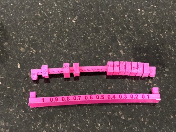
The design broke off into two parts in the water. I tested the clearance of the pieces, and all rotated except the last one with the 0.1 mm clearance. This was not surprising at all, I expected the most of the pieces to move, but also due to the cavities the pieces with a very small clearance rotated as well.
I had a third attempt at the design hence I wanted something that is neat and provided accurate and detailed results. For this attempt I decreased the support angle to 65 hence covering more of sides of the design.
The print duration was 4 hours and 28 minutes
And the results:
The clearance test was much more accurate this time. Almost all the pieces rotated except for last three pieces with a tolerance of 0.3 mm,0.2mm,0.1mm.
Bridging in 3D printing : is when printing a flat horizontal link between extended points in mid of the air, Of course, adding a support structure can be the solution, but we want to test the ability of printer to have draglines of plastic between printed parts in a way that plastic will not crash.
For the print test we did used the provide .STL file from 3D scanning and printing page of the Fab Academy website.
Next,I did use Ultimaker CURA to prepare the design for printing.
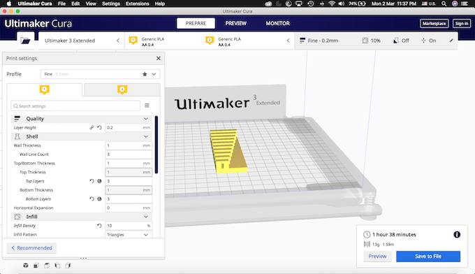
for the Print Settings are shown below in image:
The printing duration is 1 hour 38 minutes
The detailed steps of using the software shown in my website.
The images below show the test after printing from different sides:
Results:
As shown the results were really perfect from 2 - 20 mm we were able to have bridges without falling down.
In 3D printing, final results might look the same on the outside, but when in it comes to what’s inside could differ a lot. Parts in 3D printing can have different degrees of hollow which has a major effect on the overall printing time. Ofcourse on a larger scale and from a production perspective, this reduces material and cost as well as the weight of the final product.
An infill is what sits inside a 3D print’s outer shells, and it can be adjusted with respect to density ranging from 0-100 where 0% is hollow and 100% is solid.
For the purpose of using time efficiently, I searched for the best pattern that can be applied from CURA software options and I found that we can categorize the type of infills depending the object that we will print whether it is a Low Strength, Medium Strength, High Strength, or Flexible 3D Prints.
Since I’m doing a test, I went for the Medium strength option to avoid the longer printing duration and to be able to compare the results. I chose the triangular pattern to be more specific where a 2D mesh is made from it which results in a good strength for the object printed when a load is applied perpendicular to its face.
I chose 4 density percentages to test them (0%,15%,50%,100%). The testing shape was a cube which I designed using Tinkeracad and exported it in .stl format so that i can import it in CURA. I changed the height of the cube though in the later tests to be able to finish all tests on time.
Tinkercad 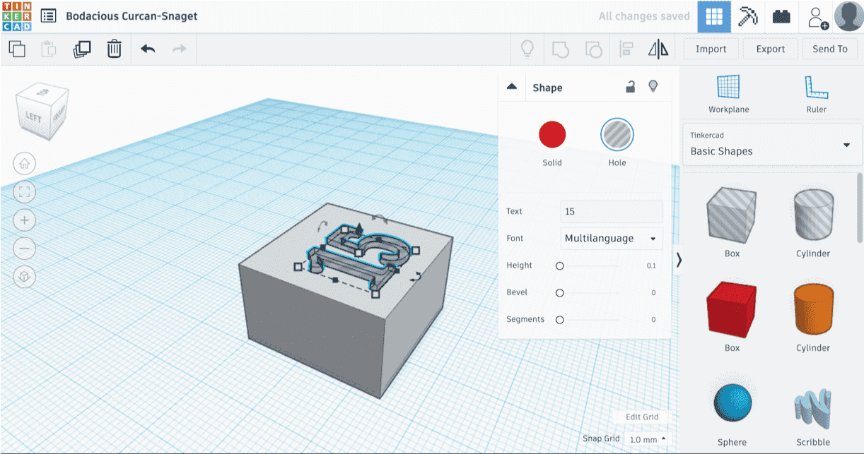
CURA 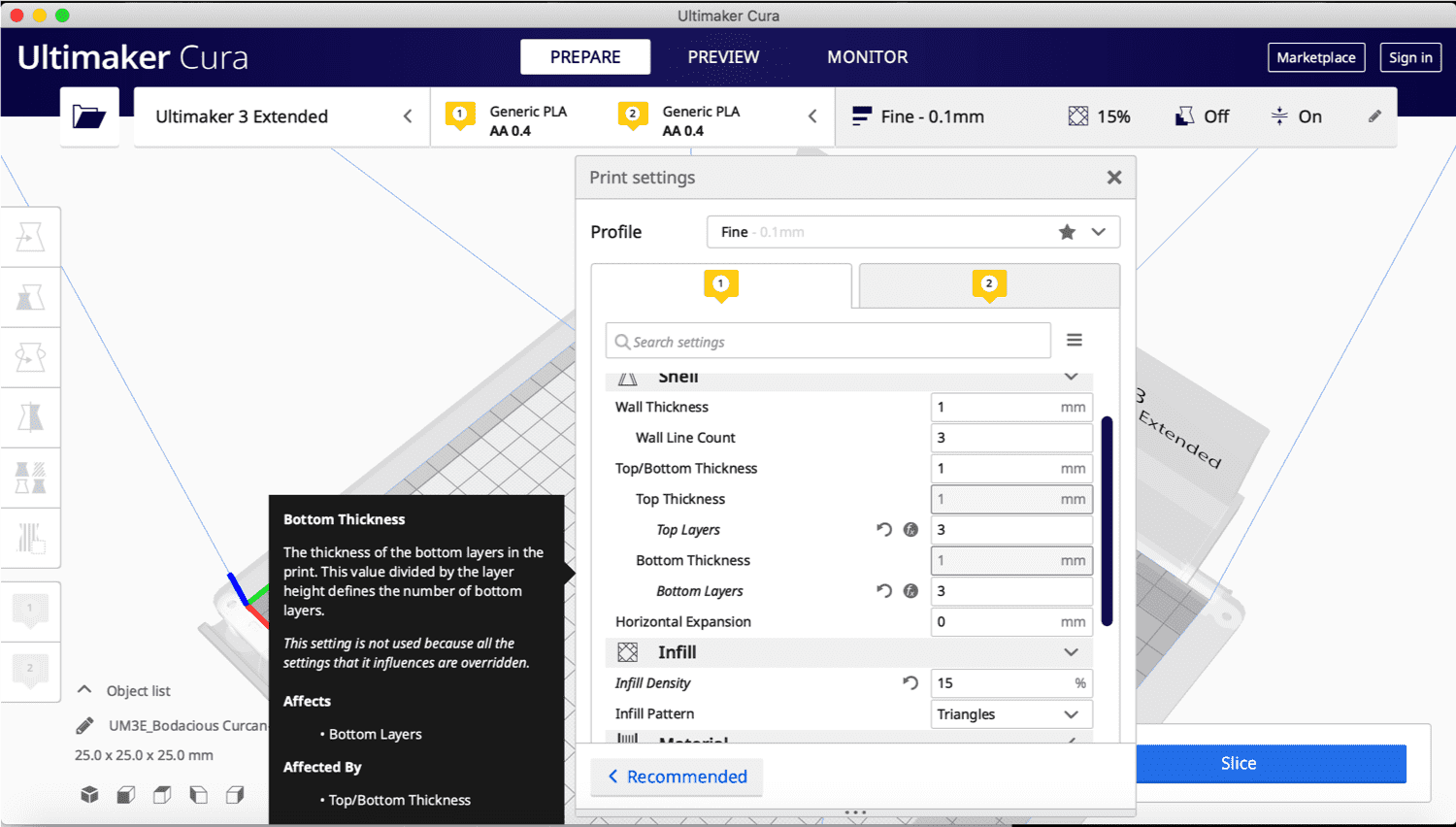
After that i saved the file on a usb to be able to transfer it to Ultimaker3 machine for the printing process.
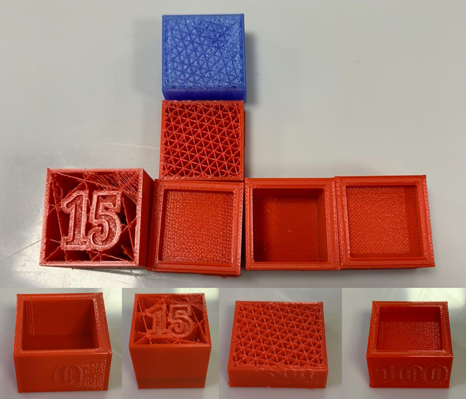
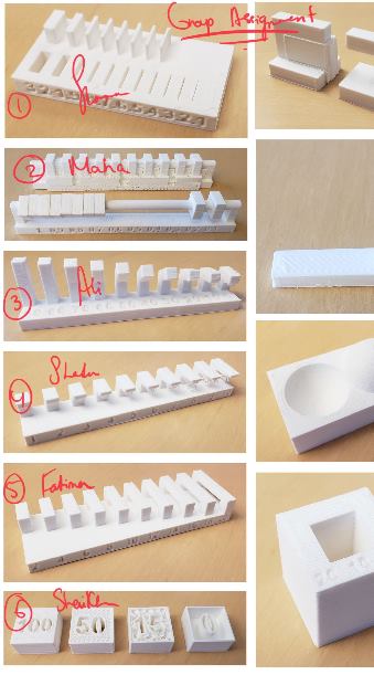
Results
I had many trials, in order to see the infills i should stop the printing process before it gets to the top layer, which i missed in the beginning. The pictures below are ordered according to the density percentages from 0 to 100 consecutively.
Finishing means how the object looks like or the appearance of the object. Its works to smooth out uneven surfaces.
As we know the layers lines on the objects are the thickness. Hiding the layers lines is what the finishing test process all about. So the purpose of this test is to check if the print hide the layers and make the object smooth. also this test check the angle of the printer
1- First I downloaded the .stl file from the fab academy page.
2- I opened Cura to prepare the design.
3- The below values are the values that I chose for my test:
4- After clicking on slice a new screen appeared to shows the duration of my test which is 54 minutes
5- Then I moved to the printer to start the printing process and this was how the object looks like:
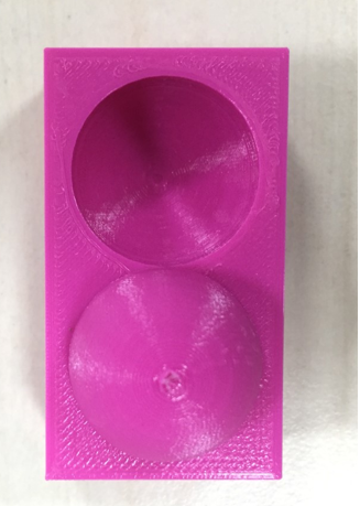
The result of the test is perfect the finishing of the object looks good. the object is smooth and the layers are not shown clearly.
The edge of the object is not sharp
Ali salem angle test
In group assignment I choose the angle no.3.
I downloaded the STL file directly from the 3D scanning and printing page of the Fab Academy website. angle.stl
The secand step was to slice it using Cura. The general values I used In the picture below and the material . PLA 0.4MM
 .
.
After saving the file on my flash drive, I headed to the Ultimaker 3D printer extended to start printing.
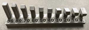
For this model angle I printed it starting with it being standing upward and then bending at 90 degrees as the machine is printing it. The models that start at 40 it starts to bend at an angle until it is at 90 degrees. The PPL for the model will get bad the more the model is bending and the PPL will get better the more the model is straight upward. The PPL is low because the model gets harder to be printed because of the angle.
In 3d printing the printed model dimension might differ from the real design due to different reasons, to find out how accurately the printer is printing , calibration cubes being especially useful for this reason,
for that reason I downloaded the cube stl file from the fabacademy page,
then I used the slicing software Cura to prepare the file for printing,
Due to the fact that this print is only for printing purposes, I wanted to make use of the time and not spent huge time on printing therefore I adjust the settings as follow:
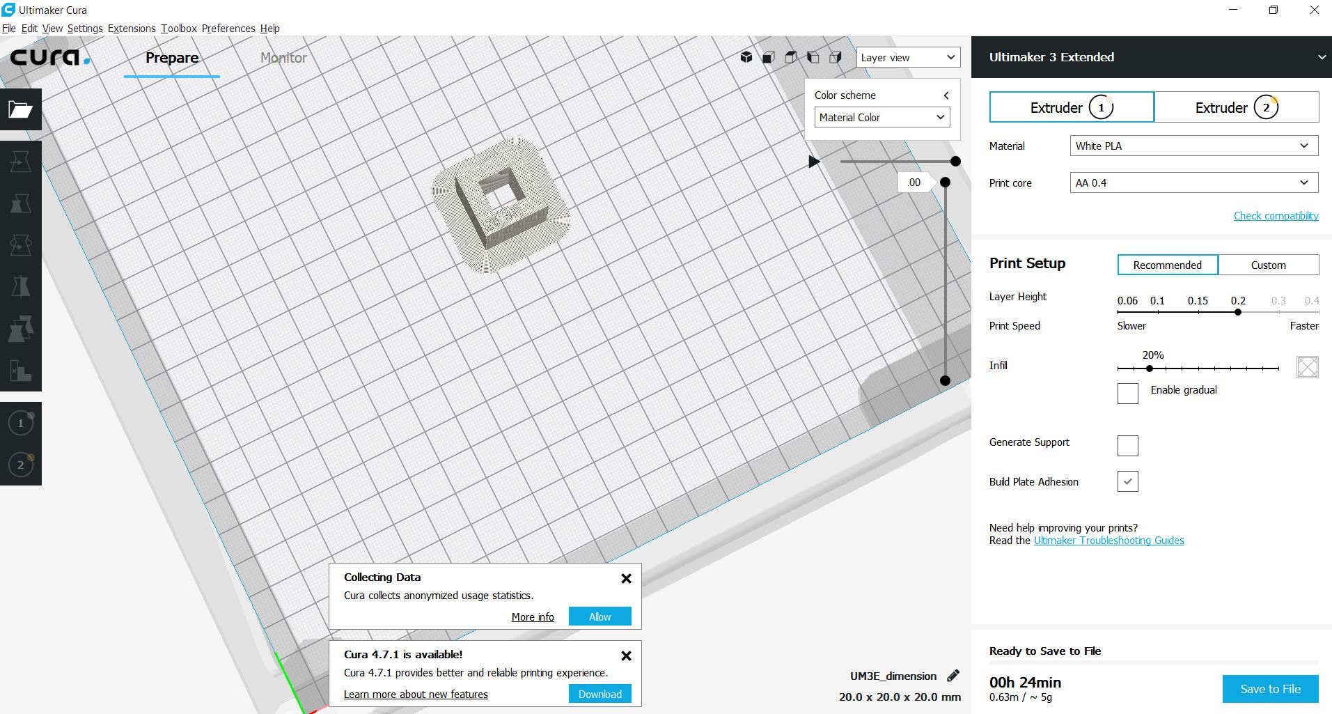
The printing duration took almost 30 minutes
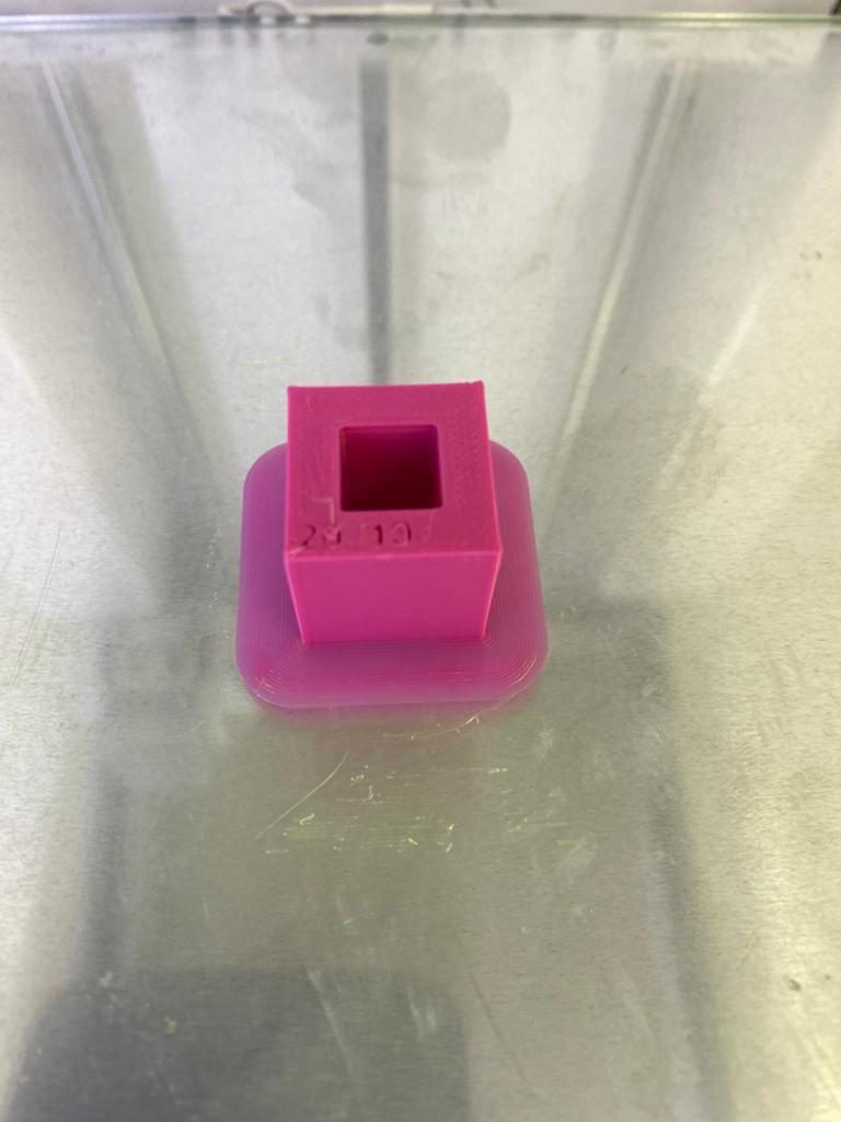
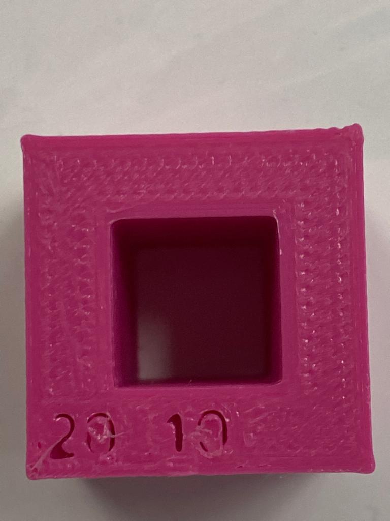
The result of print was as follow the outer width of the printed model was 19.88 which is -12mm difference from the design dimension, and the inner width is 9.6 which is -0.4mm difference from the original design, also it can easily be observed that the quality of the numbers are bad and not clearly visible.