4. Computer controlled cutting
Assignments for week 3 :
-
This week we have a group assignment and an individual assignment.
-
The group assignment is to characterize our lasercutter’s focus, power, speed, rate, kerf, and joint clearance.
-
The individual assignment is to cut something on the vinylcutter, design, lasercut, and document a parametric construction kit, accounting for the lasercutter kerf, which can be assembled in multiple ways.
The goal for this week is to acquire the knowledge about computer control cutting techniques and devices and use those techniques, also to use the vinylcutter, lasercutter machines and to characterize them.
after that, trying dissimilar materials like cardbard, acrylic, polywood, MDF and applying what we have learn in the previous week about designing using parametric softwares in order to create the ideal pressfit module using cardboard.
Files to download :
I have included all the files that you need to download down below and here you can find them directly :
Group assignment :
For the group assignment we have to learn about the lasercutter and design a module then cut it, so we have started by learning about the lasercutter and how the laser actually cuts throw different materials.
first of all laser stands for “Light Amplification by Stimulated Emission of Radiation”, we can use the lasercutter not just to cut but also to engrave, mark, raster, screen printing, pressfit construction and much more, there are also lots of cutting mechanisms such as : burning, melting, evaporation and ablation.
Before using the lasercutter you have to keep in mind those safety rules :
-
Only operate the machine while an instructor is in the room.
-
Never leave the laser cutter unattended.
-
Only cut materials approved by your instructor.
-
Keep the lid closed at all times, unless loading material while the laser is turned off.
-
Clean up debris in the laser cutter.
-
Identify the fire extinguisher and fire blanket.
Also before cutting you have to prepare the machine by :
-
Lift the lid, insert your material on the honeycomb, and close the lid.
-
Flip on the power strip and perform and check Make sure the air compressor is on: listen or touch the machine to make sure it’s running.
-
If venting outdoors, a fan may be attached in place of the air filter. Make sure it’s turned on.
-
Connect to laser cutter via either a USB or Ethernet cord.
-
Consult your instructor if you have difficulty connecting.
-
Home the laser by hitting the home button on the machine or the icon on the Retina Engrave software.
-
Homing sends the laser head back to its starting position so that the machine can know exactly where the laser head is while the laser cutter is turned on.
-
Move laser to where you’d like to start cutting or engraving - by default, the top left corner of the design is the starting location.
-
Focus the laser by adjusting the height of the laser head.
-
The aluminium measure tool is used to ensure the laser is 2” above the cutting surface.
-
Perform perimeter check to ensure the design fits on the material.
-
Adjust the power and speed settings of the machine.

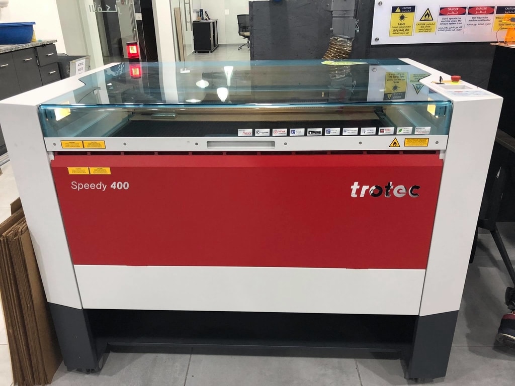
Now we are ready to characterize the lasercutter and in our lab we have the “Speedy 400 trotec”
- First we opened the laser and cleaned the lenses so the laser is 100% clear :
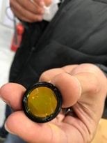 +
+ 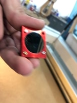 +
+ 
- Now we started to design and adjusting the power, speed and frequency for different materials:
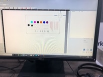
first we designed the test for marking, engraving, raster and cutting and we came up with this design:
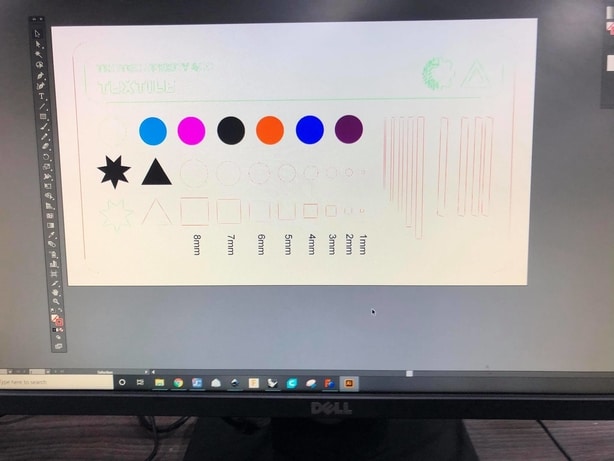
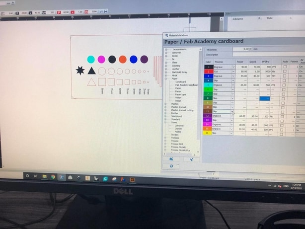
After that we started to change the settings for power, speed and frequency for this test design
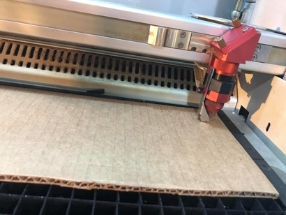
Then we inserted the design and moved the laser on the cardboard so we can start cutting on cardboard :
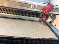 +
+ 
This is the final result :
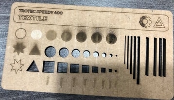
After that we did the same design and cut it on different material “textile” and ended up with this :
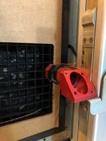
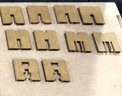
Then we demonstrated the joints and how we can use each one in a different way :
 +
+ 
Finally we designed a test for living hinges and tried it on two different materials “cardbard and textile” and ended up with this :
It was an amazing experience to work as a group and experimenting new techniques with different type of materials.
and thats it for the group assignment.
individual assignment :
For the individual assignment i have to :
-
cut something on the vinylcutter.
-
design, lasercut, and document a parametric construction kit.
-
accounting for the lasercutter kerf, which can be assembled in multiple ways.
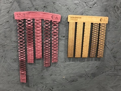
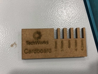
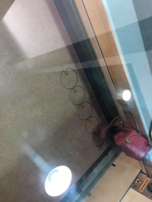
Fisrt i started with the press-fit comb and thats for calculating the slot sizes and here is the process :
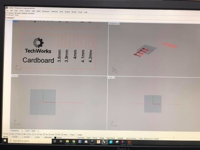
this is the design :
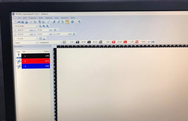
here is the right settings for cardboard “power, speed, frequency” also the time that the lasercutter need to finish the job :
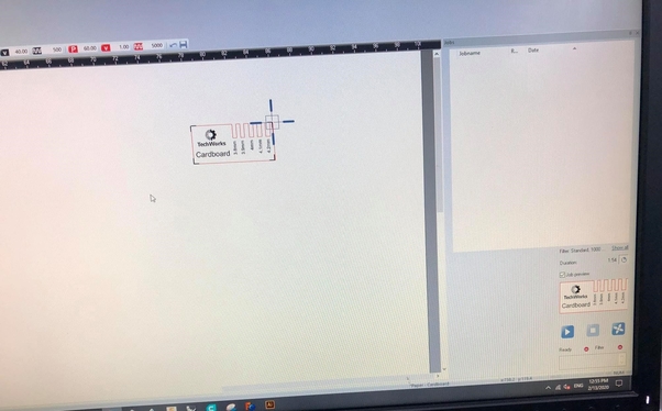
here i adjusted the laser on the right top of the design :
here is the final result :
After that i copied it and did again to end up with this :
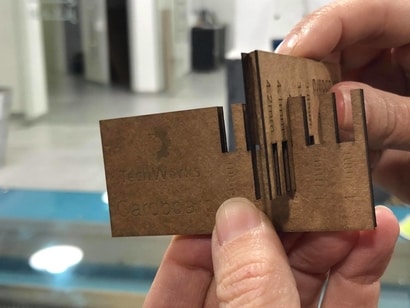
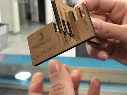
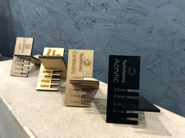
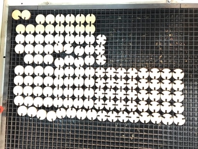
The outcome of the kerf test :
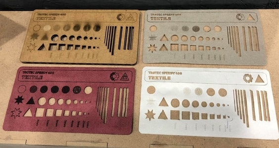
- Then i tried the same design for different materials “cardboard, acrylic, polywood, MDF” and ended up with this hero shoot for the lasercutter :
Carboard: thickness 4mm, kerf : 3.9mm

MDF: thickness 3.3mm, kerf : 3.0mm

Acrylic: thickness 2.7mm, kerf : 2.7mm

Plywood: thickness 5mm, kerf : 4.8mm
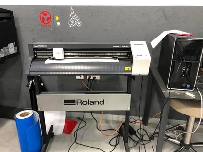
Now for the vinylcutter “characterizing” the one we have in our lab and its “roland gs-24 camm-1”
Before using the vinylcutter there are some safety rules every user must be aware of
Vinyl Cutter Safety :
-
You SHALL notify SpaceShop staff prior to running any job.
-
You SHALL wear closed-toe shoes at all times.
-
You SHALL wear eye protection when working with tools and processes that involve chemicals, metal shards, wood chips or sawdust.
-
You SHALL clean up your space after every job session, and leave 10-15 minutes for cleanup prior to shop closure.
-
You SHALL secure badge and any loose items that might get caught in moving machinery.
-
You SHALL clear the area around the cutter before turning on the machine.
-
You SHALL use test strips before working on your final product to make sure the machine is working properly.
-
You SHALL always handle the blade carefully.
-
You SHALL NOT leave a machine unattended while in operation.
-
You SHALL NOT work alone while in the SpaceShop.
-
You SHALL NOT use liquids, metals, or flammable objects inside the cutter.
-
You SHALL NOT leave the vinyl cutter unattended while a job is in session.
-
You SHALL NOT place hands or other objects in the path of the cutting arm while the job is in session.
-
You SHALL NOT lean on the machine.
-
You SHALL NOT wear ties, belts, or leave hair down while cutting arm is in operation.
-
You SHALL NOT manually stop the machine while it is in motion.
-
You SHALL NOT move the cutting head while the machine is turned on.
Now we have to prepare the machine so we can use it :
-
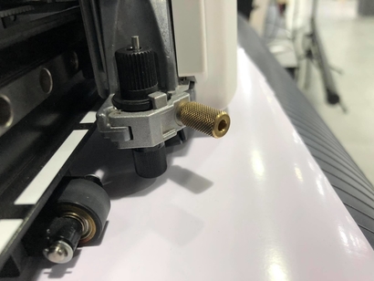
Turn the LOCKING KNOB COUNTER-CLOCKWISE on the BLADE HOLDER ASSEMBLY, to remove the BLADE HOLDER.
-
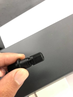
While rotating the BLADE HOLDER COUNTER-CLOCKWISE, gently pull up until the BLADE HOLDER pops out of the BLADE HOLDER ASSEMBLY.
-
INSPECT the BLADE TIP for damage.
-
If the BLADE TIP is damaged, hold the BLADE HOLDER LOWER HALF in your left hand and with your right hand, gently rotate the BLADE HOLDER TOP HALF counterclockwise until you have both parts separated.
-
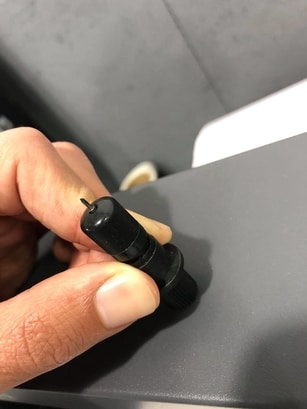
Press DOWN on the PLUNGER sticking out, and notice the blade moving down as you do. If you LET GO, the PLUNGER and blade move back into their initial position. Note: The PLUNGER is not attached to the bottom blade. It’s used solely to move the blade to a safe position where you can now pull the blade out without having to touch the sharp edge itself.
-
Take the NEW BLADE and place in SAME DIRECTION, sharp end facing out and PUSH GENTLY into the BLADE HOLDER, until an inner MAGNET pulls the blade back into place.
-
Place the bottom half of the BLADE HOLDER disassembled in STEP 4 in your left hand, and the top half in your right hand. Rotate the bottom knob in your left hand, CLOCKWISE until the top edge now joins the top half in your right hand. Notice: You can still press down on the top PLUNGER, but if you GENTLY try scratching a surface, then the blade should cut through the vinyl, resisting movement back into the BLADE HOLDER. It is now secure and ready to be placed back in the BLADE HOLDER ASSEMBLY. We will later ADJUST FORCE SETTINGS, to apply pressure on the PLUNGER thus affecting how deep the blade cuts.
-
Place entire BLADE HOLDER back into the BLADE HOLDER ASSEMBLY and rotate the LOCKING KNOB CLOCK-WISE to tighten the assembly.

Now the blade is ready.
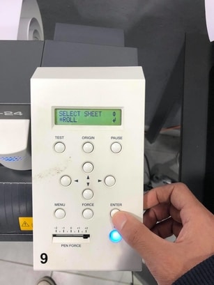
- First we turn on the machine by pressing this button :

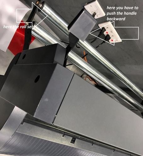
- Then we insert the roll and chose the option “roll” :
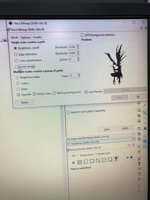
- After that we enter the design, picture on Inkscape to invert the colors and do the outshape of the picture :
Here we drag the design to Inkscape :
Here we set the right settings for the picture and we click on invert image :
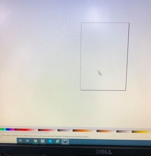
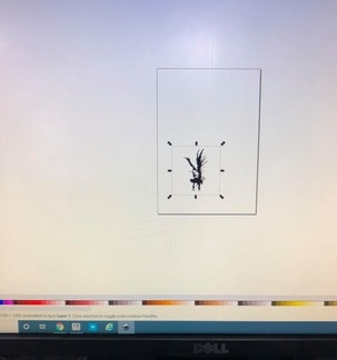
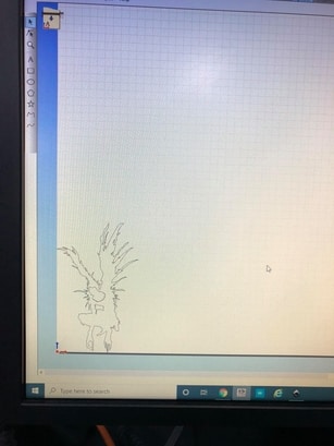
Now we copy the picture and open “Roland” the vinylcutter software to insert the picture and place it on the origin place :
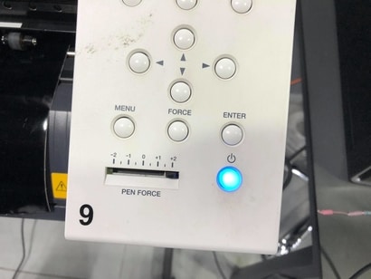
And now we are ready to cut the picture but first we must check the pinforce in order to get the finest cut:
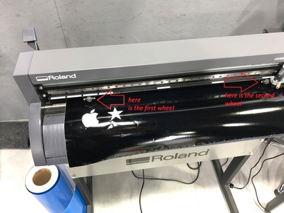
Also we must check the wheels to fit on the right place so we can use the right amount of material :
Now we are ready to cut and here is the process :
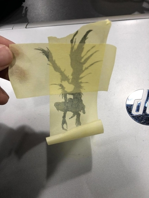
This is the final outcome :
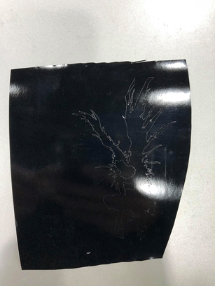
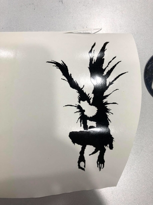
Then we remove the outline sticker and end up with this :
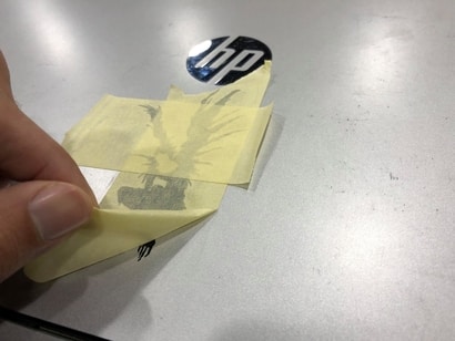
After that we stick the paper tape on it and gently remove it to come up with the picture we want like this :
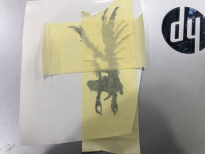
Now we put the picture where we want it to be and again gently remove the paper tape like this :
This is the hero shoot for the viynalcutter :
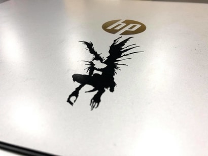
And thats all for the vinylcutter.
Now for the laser cut design :
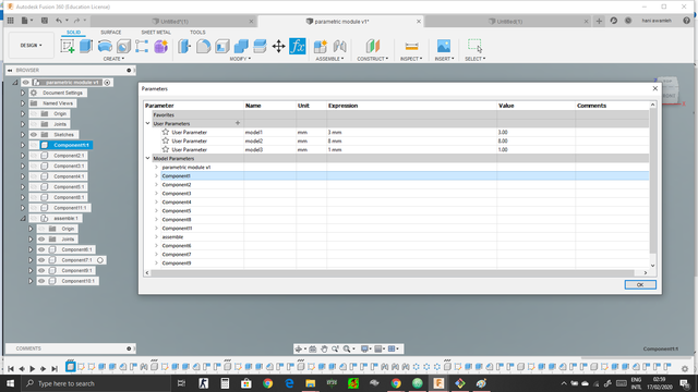
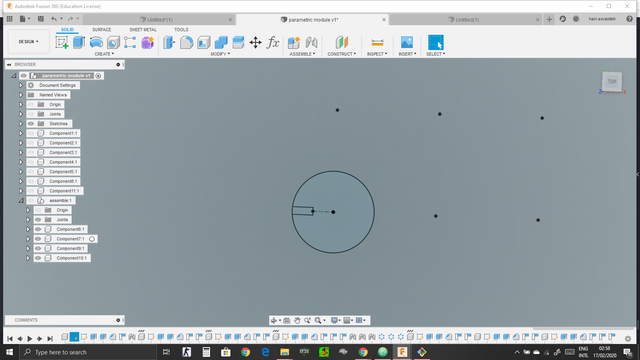
The design have to be parametric so i decided to use fusion 360, and here is the process :
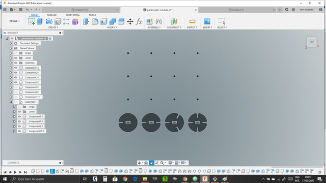
- First i created the parametric table and entered the values for my module :
- Then i started as usual with a 2D skitch and the dimensions were the one i have written in the table :
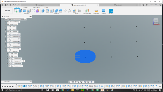
- Now i extruded this 2D skitch to get a 3D object and again the extrusion was by using the parametric table :
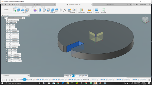
- Here after the extrusion i did a chamfer to the joints can fit in a good way :
- Then i added a rectangle pattern so i can extended the design :
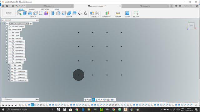
- After i made the pattern i copied the first design and made another 3 similar designs, then on each one i made a circular pattern in order to repeat the chamfers like this :
- Finally i have joined the parts with each other and ended up with this parametric design :
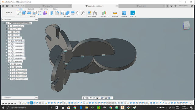
- The Hero shoot of the design :
- Now i saved the file as DXF in order to cut it on the lasercutter using cardboard and ended up with this module : Click here to see the design + Click here to see the design
- Here the laser started to cut :
- This is the outcome :
- Now i started assembling part by part and started with this shape :
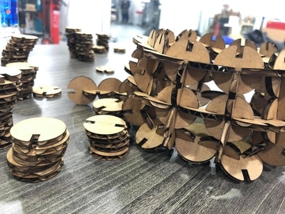
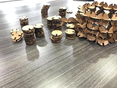
- And here is the final result :
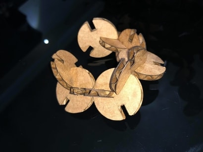
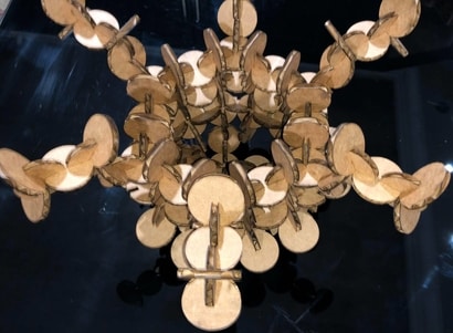

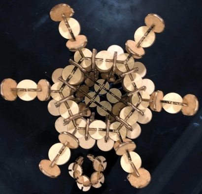
The hero shoot of the lasercutter module :
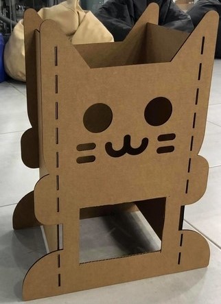
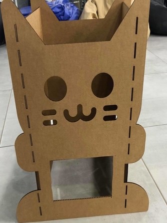
The design for the final project using cardboard :
Here i designed a case for my final project the previous week and in this week i cut it using lasercutter and here is a the case :
And here is a look for the design when it is finished :
the settings for the lasercutter :
 Function : Cut CO2

 Power : 20

 velocity :40

 PPI/Hz : auto

 Passes : 1

 Offset : 0
