9. Embedded programming
Assignments for week 8 :
-
This week we have a group assignment and an individual assignment .
-
The group assignment for this week is to compare the performance and development workflows .
-
The individual assignment for this week is to read a microcontroller data sheet program my board to do something, with as many different programming languages and programming environments as possible .
The goal for this week is to try as many programming languages and to get to know how to read a data sheet in order to program a board and in my case the board i am going to program is the one we have made on Week 6 which is the “Hello world” .
Files to download :
I have included all the files that you need to download down below and here you can find them directly :
-
Fuse calculator (right click on the link and “save as”)and open the html inside.
Group assignment :
For the group assignment this week i have to compare the performance and development workflows for other architectures and i have done that individually which you can see in my individual assignment .
individual assignment :
For the individual assignment i have to read the microcontroller datasheet and to program my board that i have made on Week 6 to do something, with as many programming languages possible also to use the “ISP” that i have made on Week 4 as a programmer .
What is the “ATtiny44” ?
-
I have used the “ATtiny44” as a microcontroller
 , So i have to read the ATtiny44 datasheet.
 -
First what is a datasheet : Datasheets, are instruction manuals for electronic components, they explain exactly what a component does and how to use it.
-
The first page is usually a summary of the function and features of the component. You can quickly find a description of the functionality, the basic specifications (numbers that describe what a component needs/can do and sometimes a functional block diagram that shows the internal functions).
-
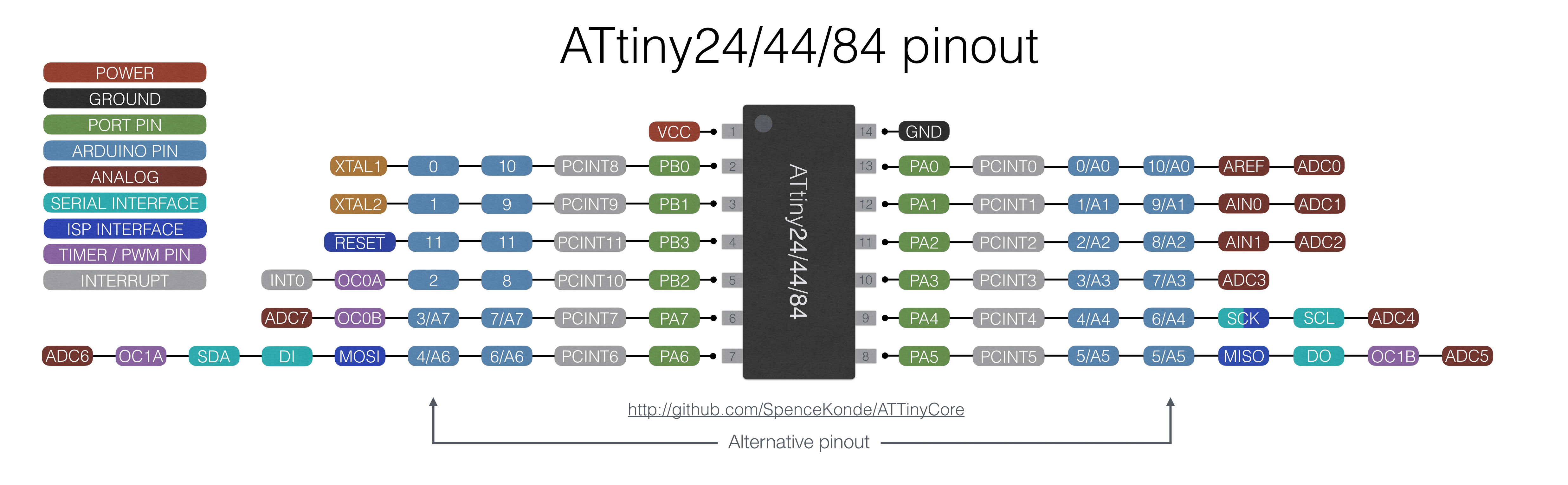
Pinout lists the component’s pins, their functions, and where they’re physically located on the component.
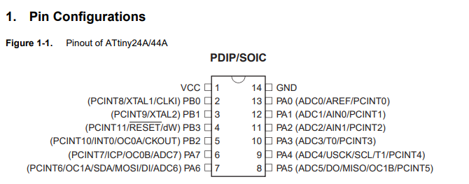
Pin configurations And Pin descriptions :
- Here you can see the Pin configurations and the Pin descriptions of the ATtiny44 :
-
VCC : Supply voltage.
-
GND : Ground.
- Port B (PB3…PB0) : Port B is a 4-bit bi-directional I/O port with internal pull-up resistors (selected for each bit). The Port B output buffers have symmetrical drive characteristics with both high sink and source capability except PB3 which has the RESET capability. To use pin PB3 as an I/O pin, instead of RESET pin, program (‘0’) RSTDISBL fuse. As inputs, Port B pins that are externally pulled low will source current if the pull-up resistors are activated. The Port B pins are tri-stated when a reset condition becomes active, even if the clock is not running.
- RESET : Reset input. A low level on this pin for longer than the minimum pulse length will generate a reset, even if the clock is not running and provided the reset pin has not been disabled. Shorter pulses are not guaranteed to generate a reset. The reset pin can also be used as a (weak) I/O pin.
- Port A (PA7…PA0) : Port A is a 8-bit bi-directional I/O port with internal pull-up resistors (selected for each bit). The Port A output buffers have symmetrical drive characteristics with both high sink and source capability. As inputs, Port A pins that are externally pulled low will source current if the pull-up resistors are activated. The Port A pins are tri-stated when a reset condition becomes active, even if the clock is not running. Port A has alternate functions as analog inputs for the ADC, analog comparator, timer/counter, SPI and pin change interrupt.
maximum ratings :
- Now after i have read about the pin description i have to know about the maximum ratings :
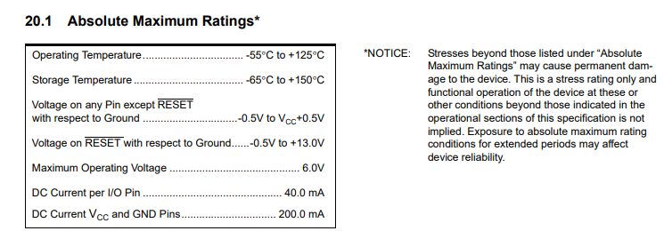
in this list you can see what is the maximum ratings for the component that if i crossed it will be damaged .
Fuses :
- Then after learning about the maximum ratings i have to know what is a fuse :
There are 3 bytes of permanent storage in the chip called ‘fuse low byte’, ‘fuse high byte’ and ‘fuse extended byte’. These bytes are called fuses and can be reprogrammed as many times as you want and determines the behaviour of the chip. To do that, their value is not erased when the chip is powered off or reprogrammed.
Each microchip has its own definition for the values that must have the fuses and we are going to work with the fuses of the Atmel Attiny44A.
| Name | Description | Default Value | Byte | Bit range | Datasheet page |
|---|---|---|---|---|---|
| CKDIV8 | The pre scaler feature can be used to change the power consumption when not high performance is required. This feature can be used with any clock source. The pre scaler divides the clock frequency by a defined factor that can be configured using the CLKPS(3…0) register (Datasheet - Table 6-11), being its default value “0011” (division factor of 8). | 0 | LOW | (7) | 30 |
| CKOUT | This fuse allows us to use the chip clock as a clock source to drive other circuits. Once this bit is programmed, the PIN B2 will output the clock. | 1 | LOW | (6) | 30 |
| SUT | This fuses determine the Start-up Times for the external clock selection. This time must be long enough to ensure that the MCU is kept in reset mode while the clock is changing (is not stable). Its default value defines the longest Start-up time. | 10 | LOW | (5,4) | 26 |
| CKSEL | The AMTEL Attiny44A can use several clock sources. By default, the clock used is the internal 8MHz oscillator. The available configurations can be found in the datasheet, in table 6-1. | 0010 | LOW | (3…0) | 25 |
| RSTDISBL | When programmed (0), the PB3, instead of being used as a reset pin, it can be used as an I/O pin. | 1 | HIGH | (7) | 3 |
| DWEN | This fuse allows the activation of the ‘debug’ mode. Once it is programmed, the RESET port is configured as a bidirectional I/O pin with pull-up enabled. | 1 | HIGH | (6) | 150 |
| SPIEN | Fuse that enables serial program and data downloading. Once unprogrammed this fuse, in order to reset its value, you will need a 12V programmer. | 0 | HIGH | (5) | 159 |
| WDTON | A watchdog timer is a mechanism to prevent closed loops and errors in the microchip. It consists on a decreasing counter. If it reaches 0, it generates a timeout signal that triggers an action to restore the system. To avoid this, the program must restart the timer before it times out. | 1 | HIGH | bit range | 41 |
| EESAVE | If programmed (0) the EEPROM memory will be preserved through chip erase. | 1 | HIGH | (4) | 159 |
| BODLEVEL | This fuse controls the Brown-out detector. A Broun-out detector is a circuit that monitors the supply voltage while operating. It compares the supplied voltage to a fixed one. If the supplied voltage decreases blow a fixed one (VBOT-), the Brown-out reset is enabled until the voltage raises above a VBOT+. Then a timer starts; if it times out, the reset is disabled. By default, the Brown-out detector is disabled. In table 20-6 of the Datasheet all the modes are specified. | 111 | HIGH | (2…0) | 159 & 176 |
| SELDPRGEN | This fuse, if programmed, allows to the device the ability to upload a program to the MCU by itself. | 1 | EXTENDED | (0) | 152 |
As seen, there is just one bit in the Extended byte of the fuses whose value will change the microchip behaviour. The bytes 7…1 should be set with a value of 1.
Fuse Calculator For using the fuse calculator you need to download this folder (right click on the link and “save as”)and open the html inside.
Programming :
The brain of the project will be growing from now on, and to do that i had to research for three straight days on how to program an attiny and here is the process :
- I want to document this process step by step in order to help out everyone faces a problem while programming because to be honest i suffered a lot and didnt sleep for three days until it worked for me, also a lot of people are using “Windows” so that will be a big help for them, lets start and hope it work for others too !!
How to start :
- To start programming you have to download all the “Drivers” and “Tools” and i will list them one by one so you can get them easily.
Downloading Arduino IDE:
- For me i used “Arduino IDE” and you can download it by Clicking here.
Adding the Attiny library :
-
After successfully downloading “Arduino IDE” you have to download the “Attiny Library” and for i have used the “Attiny44” and here is how to do it :
-
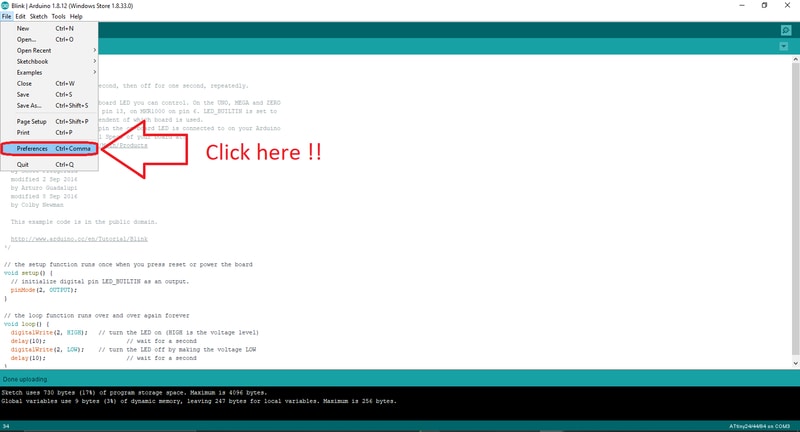
First open Arduino IDE and go to Files>> Preferences, And this window will appear :
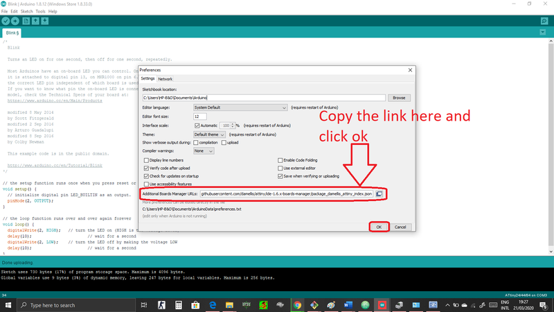
- Copy this link
https://raw.githubusercontent.com/damellis/attiny/ide-1.6.x-boards-manager/package_damellis_attiny_index.jsonand paste it in “Additional board manager URLs” as shown in the picture :
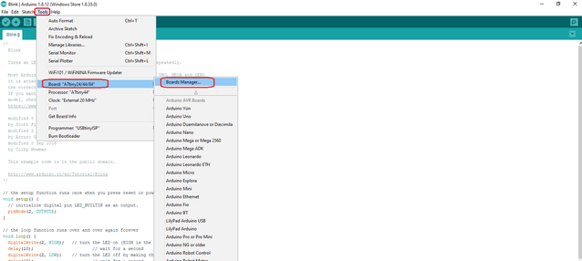
- Now got to Tools >> Boards >> Board manager, as shown in the picture :
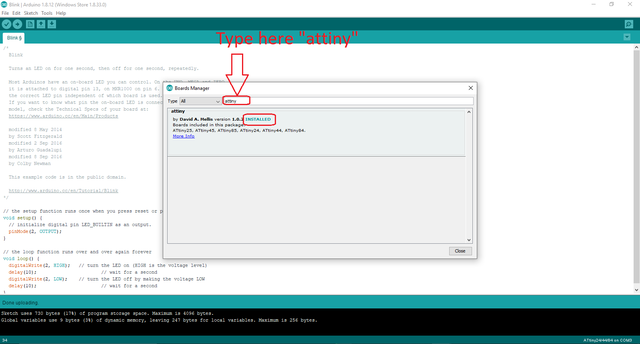
- This window will appear as shown in the picture and type “Attiny“ and click on install :
Downloading “tools” and “Drivers” :
- You have to download the toolchain for windows first and you can do that by just Clicking here, i have spent 2 hours just looking for the right toolchain :)
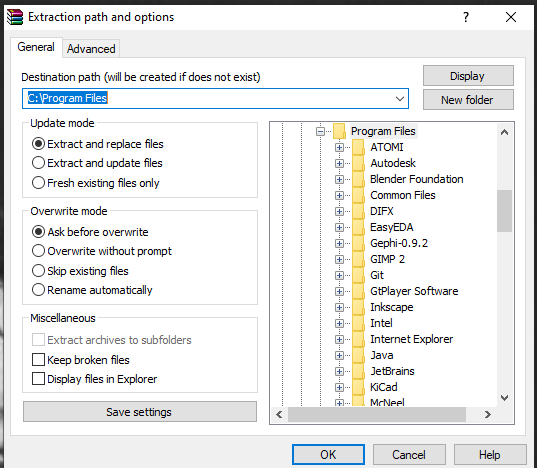
after successfully downloading the zip file, extract the file on {C/ Program files} if it didnt work which happened with me and kept giving you errors just extract the file on your desktop and cut it then paste it on {C/ Program files} .
-
Now you have to download GNU Make and to do that just Click here when you successfully download it just open it and accept the default location for the installation but keep it mind i you wanted to change it into other location .
-
Now you have to download Avrdude and to do that just Click here when you successfully download the zip file and extract the file on {C/ Program files} and if it didnt work just do as point 1 .
-
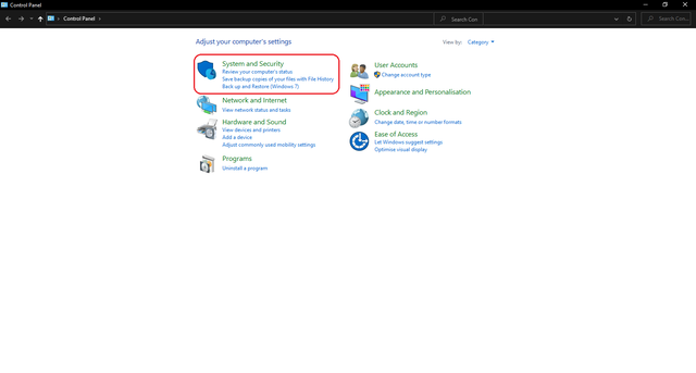
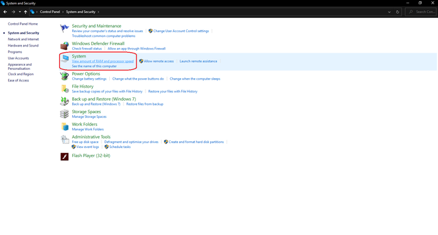
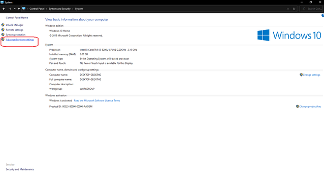
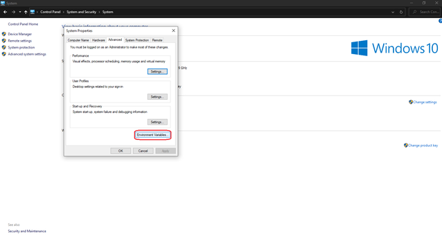
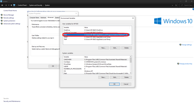
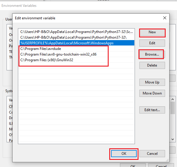
Now you have to Update your path, maybe now you are wondering why to do that but i will tell you, you have to tell Windows where to locate all of the tools you’ve just installed.
and to do that from Start menu and open the Control Panel, then go to System. From the left pane, choose “Advanced System Settings”. Under the Advanced tab, click the “Environment Variables” button and here is a look on how to do it :
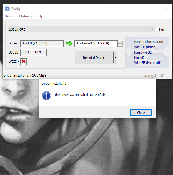
- After that you have to download drivers for your Programmer and to do that just Click here then when its successfully downloaded connect your programmer and go to Options >> List All Devices then Select “USBtinySPI” from the dropdown list and select “libusb-win32 (v1.2.6.0)” in the target driver side then Click on “Install Driver” and here is a look :
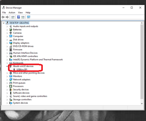
- Now after downloading everything we are ready to program our board we just need to check if the computer is recognising the programmer and to do that open “Devices manager” from the search bar after connecting the programmer and you should see this :
Programming my board :
-
After downloading everything and making sure i have all the tools needed i have opened Arduino IDE and here is the process :
-
first make sure all the settings are right and here is a look for the settings :
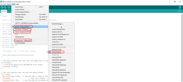
Board : choose “Attiny24/44/84”
Processer : choose “Attiny44” if you are using ATtiny44
Clock : choose “Extended 20 MHZ” for my case because in my board i have added a crystal
Programmer : choose “USBtinyISP”
- But before doing any programming i had to know every pin reference to “Arduino”
The hero shoot for my individual assignment :
- Now i have connected my programmer with my board and uploaded a blink code from Arduino IDE to see if everything is working here is the code and here is the board actually working :
  void setup() {
  // initialize digital pin 2 (PA2) as an output referring to the ATtiny44 datasheet .
  pinMode(2, OUTPUT);
}

// the loop function runs over and over again forever
void loop() {
  digitalWrite(2, HIGH);
  delay(10);
  digitalWrite(2, LOW);
  delay(10);
}
- Now i have programmed my board to blink the LED if the button is pressed twice and here is the code and the board actually programmed :
int led = 2; // as PA2
int button = 8; // as PB2
int buttonlocation = 0;
int y = 0;
int previous = 0;
// the setup routine runs once when you press reset:
void setup() {
  // initialize the digital pin as an output.
  pinMode(led, OUTPUT);
pinMode(button, INPUT);

}

// the loop routine runs over and over again forever:
void loop() {
  previous = buttonlocation;
  buttonlocation = digitalRead (button);


      if (buttonlocation == 1 && previous == 0)

    {

      y = y +1;

     }
        if (y == 2){
           digitalWrite(led, !digitalRead(led));   // turn the LED on (HIGH is the voltage level)
           y = 0;
        }

}
- Here i programmed my board to stop blinking if i pressed the button, here is the code and here is a look :
const int buttonPin = 8;  // As PB2
const int ledPin =  2;   // As PA2

// variables will change:
int buttonState = 0;         // variable for reading the pushbutton status

void setup() {
  // initialize the LED pin as an output:
  pinMode(ledPin, OUTPUT);
  // initialize the pushbutton pin as an input:
  pinMode(buttonPin, INPUT);
}

void loop() {
  // read the state of the pushbutton value:
  buttonState = digitalRead(buttonPin);

  // check if the pushbutton is pressed. If it is, the buttonState is HIGH:
  if (buttonState == HIGH) {
    // turn LED on:
  digitalWrite(2, HIGH);
  delay(10);
  digitalWrite(2, LOW);
  delay(10);
  } else {
    // turn LED off:
    digitalWrite(ledPin, LOW);
  }
}
And thats all for the individual assignment .