5. Electronics production
Assignments for week 4 :
-
This week we have a group assignment and an individual assignment.
-
The group assignment is to characterize the design rules for our PCB production process.
-
The individual assignment is to make an in-circuit programmer by milling and stuffing the PCB, test it, then optionally try other PCB processes.
The goal for this week is characterizing the “monoFab roland SRM-20” desktop CNC machine and acquire the knowledge about PCB, soldering techniques, also why we are using ISP for.
As an electrical engineer student i have always wanted to do my own ISP board, also the background knowledge i have about electronics helped me a a lot to understand the components i have used.
Also this week was so fun because me and my instructor “Montserrat” had a challenge and that challenge was to make an ISP and get it work for the first time.
Files to download :
I have included all the files that you need to download down below and here you can find them directly :
Group assignment :
For the group assignment we have to learn about the monoFab machine and how it works then characterize this machine and how we can use it to cut and mill the board in order to solder the electronics components and program this board we have to use it as a programmer for our final project boards.
- Here are some informations about the machine and how it works also what we can use it for :
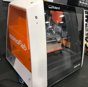
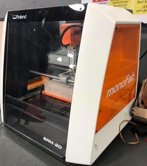
The Roland SRM-20 MonoFab Desktop Subtractive Rapid Prototyping (SRP) system is capable of 3D milling, 2D Milling, and Engraving. The SRM-20 is ideal for a variety of product designs tasks, including model making, rapid prototyping, and small lot production. The SRM-20’s compact design makes it a perfect fit for offices and classrooms. Add some of PDI’s exclusive accessories and the SRM-20 is transformed into a PC Board Prototype System, an Engraver, a Jewellery Wax Carving system.
- Before using the Roland SRM-20 MonoFab you have to keep those safety rules in mind :
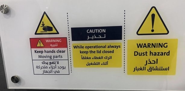
To ensure the full performance of this machine, be sure to observe the following important points. Failure to observe these may not only result in loss of performance, but may also cause malfunction or breakdown.
This machine is a precision device : - Handle carefully, and never subject the machine to impact or excessive force.
-
Diligently keep clean of cutting waste.
-
Use within the range of specifications.
-
Never attempt to move the spindle head and table by hand with undue force.
-
Never needlessly touch anywhere inside the machine except for locations specified in this manual.
This machine becomes hot :
-
Never cover the ventilation holes with cloth, tape, or anything else.
-
Install in a well-ventilated location.
About Cutting tools :
-
Use a cutting tool that is suitable for the material and the cutting method.
-
The tip of the cutting tool is breakable. Handle with care, being careful not to drop it.
Never allow children to use this machine by themselves and keep it out of children’s reach :
-
Never keep the machine within children’s reach to prevent them from inadvertently swallowing a small part, etc.
-
Restrain children from playing with the plastic bag used for packing. Pulling the plastic bag over one’s head or swallowing it may lead to suffocation.
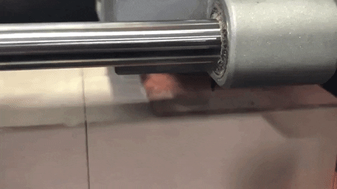
Here is the machine “ROLAND SRM-20”:
But before using machine we have to know what is mods and what we use it for
What is mods ?
Mods is a project lead by Prof. Neil Gershenfeld in the CBA that allows one connect modules, i.e. devices that do very specific tasks, using a friendly web interface. It allows people to use a web-browser to connect devices and do computation. By doing so it can be used to build modular machines that do a variety of tasks.
- Getting started with mods :
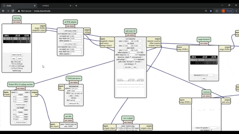
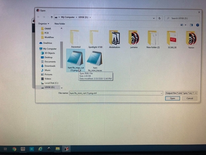
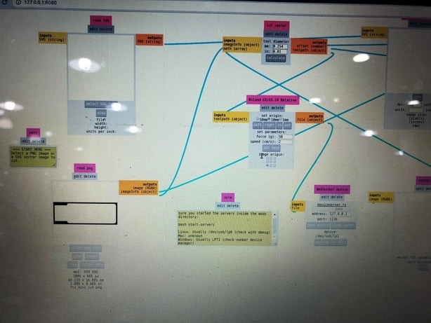
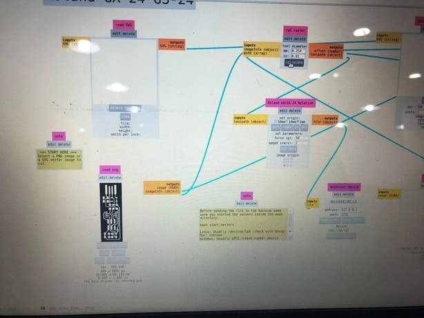
Here we choose “programs” and then we choose “open server program” then a lot of programs appears and we choose what is the machine we are using and for our case we are using “Roland”, “SRM-20”, “PCB png”.
Now we insert the png image and choose whether we want to cut the outline “interior” or the traces after choosing the 2ND mill raster will change automatically, now we put the origin axis “X=0” “Y=0” “Z=0” also i have set the offset to full so it will be 100% clean then we insert “save file” and calculate and the file automatically will be saved.
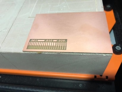
Here is the line test traces and the outline “interior” :
Outline cut for the line test “interior”


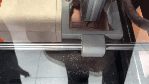
Now we get the machine ready :
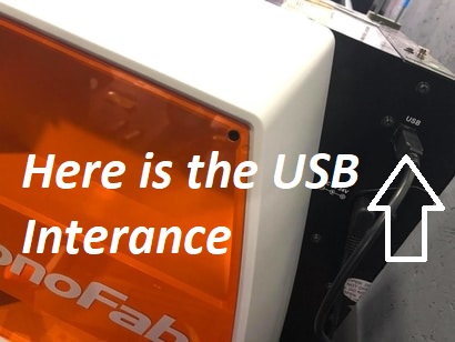
- First we connect the machine to the computer :
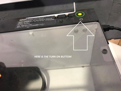
- Then we turn the machine on :
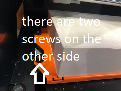
- Now we open the case in order to put the copper board on the machine bed but to do that we have to take the bed out of the machine and to do that the four screws must be loose enough like this :
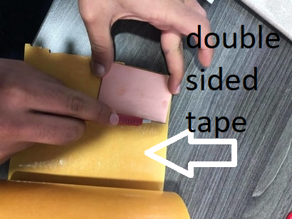
- Here we put the copper board on a double sided tape in order the copper board not to move while cutting :
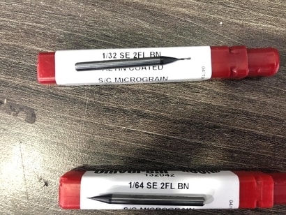
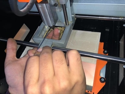
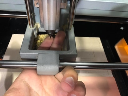
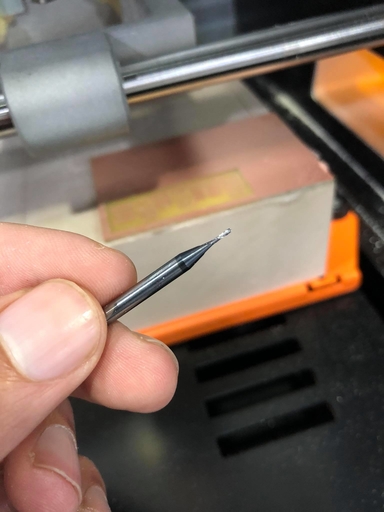
- Now we place the copper board on the bed and put it on the right side and insert the Milling bit we want to use, there are two milling bits one is for tracing and the other one is for cutting the outline, for the tracing we use the “1/64” milling bit and for the outline we use the “1/32” milling bit which look like this :
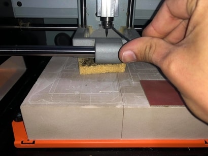
- The process of inserting the blade is carefully placing it with two fingers under and then tighten it and for extra caution we placed a sponge on the bed :
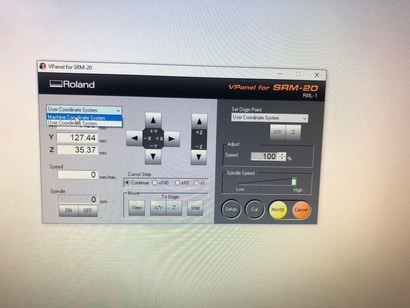
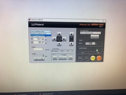
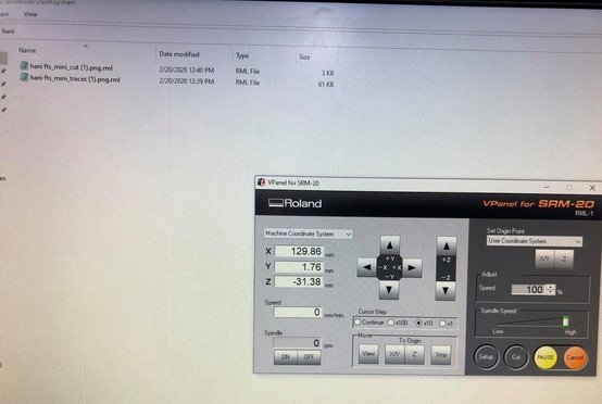
- Now we are ready to cut but first we have to put the right settings, where the option “Machine coordinate system” is to move the blade and the option “User coordinate system” is for getting the machine to cut :
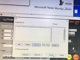
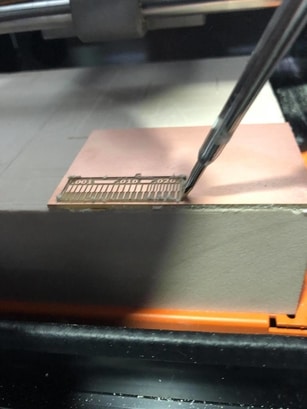
- Here we click on cut and then a window pops out showing the jobs that has been added recently so we delete them and added our job which is the linetest trace and outline :
- And now we are ready and here is the process :
The hero shoot for our group assignment :
and that is all for our group assignment.
The individual assignment :
For the individual assignment we have to make an in-circuit programmer by milling and stuffing the PCB, test it, then optionally try other PCB processes.
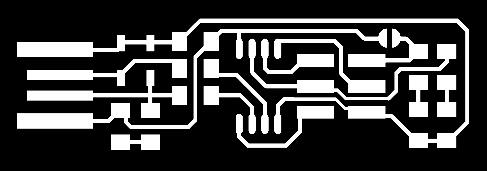
- First i have get the ISP file ready :


-
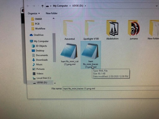
Then i have repeated the whole process that i have made in the group assignment, and prepared the files on mods.
-
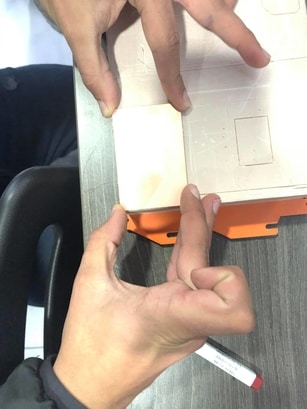
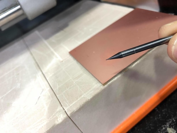
Here i have placed a new copper board and added the double sided tape and there is something important which is try not to touch the copper board from top because you will end up with your finger prints on it :
- Here i have inserted the right settings and coordinates for the machine :
- And here i inserted the “1/64” Milling bit in order to cut the traces :
- Then i have checked if the blade in the right place :
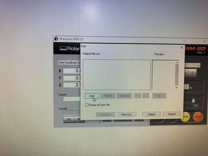
- Now i have pressed “cut” and added my traces file then i pressed output:

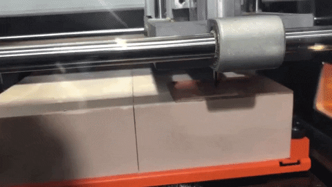
Traces Cutting
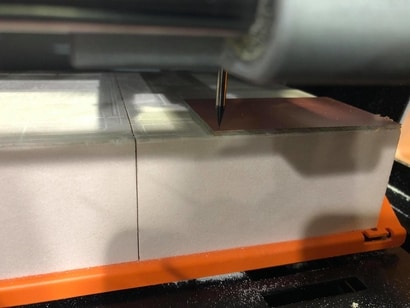
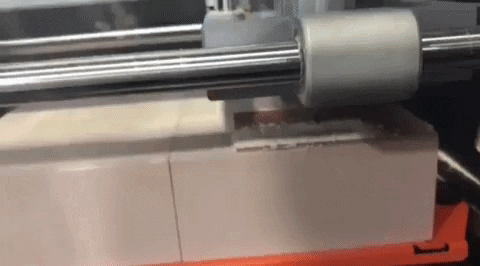
- Here the machine started cutting :
- And now we i have changed the Milling bit into “1/32” in order to cut the outline “interior” :
- Also i have set the right settings for the machine and removed the previous job then i have added the new job and started to cut :

Outline “interior” Cutting
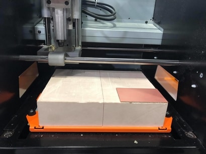
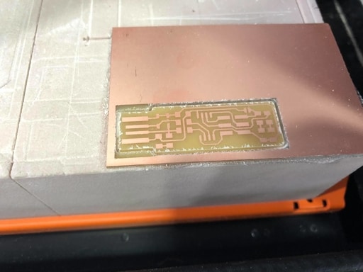
- Here is the machine while cutting the outline :
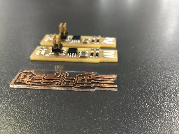
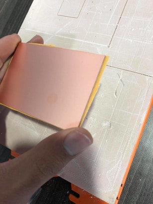
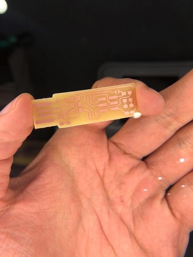
- Finally i have ended up with this beautiful outcome :
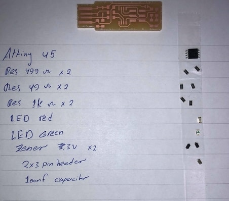
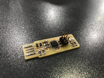
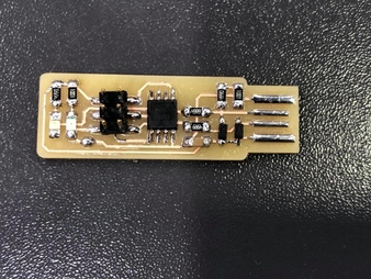
The required components
- Then I have prepared the components :
-
ATtiny45 x1
-
1kΩ resistors x2
-
499Ω resistors x2
-
49Ω resistors x2
-
3.3v zener diodes x2
-
red LED x1
-
green LED x1
-
100nF capacitor x1
-
2x3 pin header x1
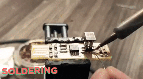
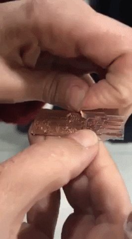
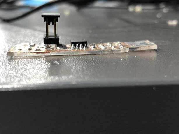
Soldering :
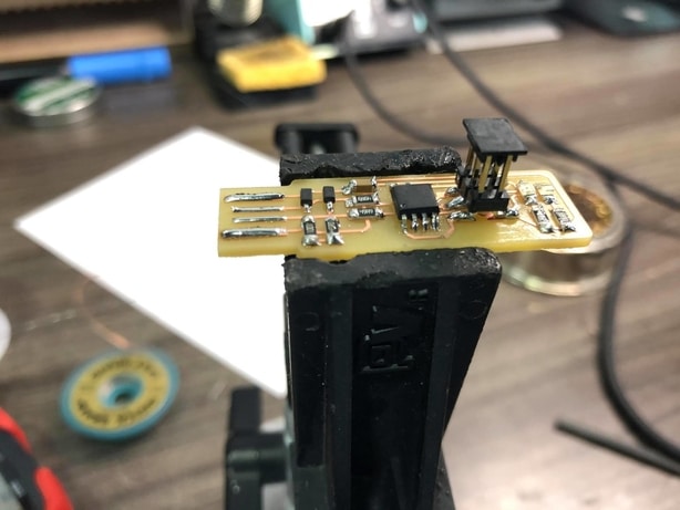
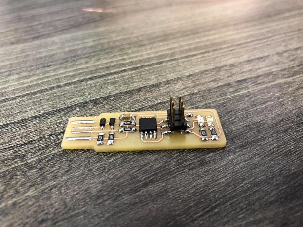
Final result
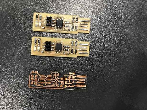
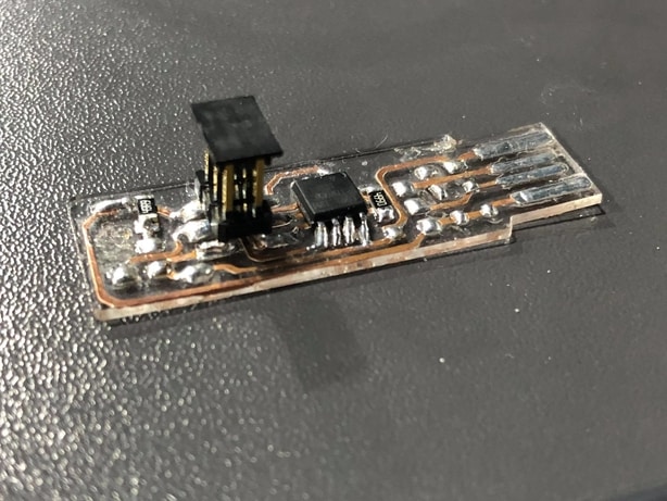
At first it worked and the blue light went on but unfortunately the laptop could not recognize the ISP after it has be programmed so i started to detect the problem and trying to see what went wrong then i decided to replace the micro controller “ATtiny45” and program it again also i have decided to make a new ISP because i was not satisfied with the soldering for the first ISP and eventually both ISP’S worked perfectly and i have won the challenge and made the two ISP’S work from the first time and here is a look for the whole process :
- Here is a look for the second ISP and to be honest the soldering for the second ISP was so elegant :
- Here i replaced the micro controller for the first ISP :
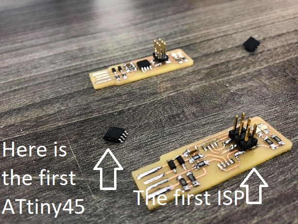
- Here is the look for the two ISP’S :
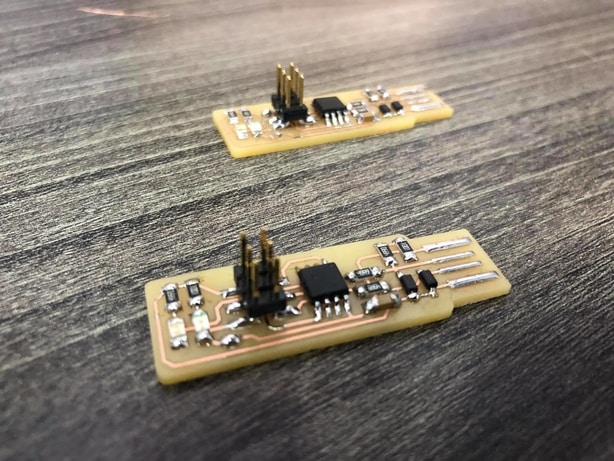
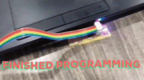
- Here is the two ISP’S being programmed :
In order to program the ISP you have to connect it with a programmed ISP first and then enter the command “make flash” then if it works enter the command “make fuse” after that to make sure your ISP is actually programmed you enter the command “lsusb” and tha will list USB devices. If you see a “Multiple Vendors USBtiny” device that means it worked.
Here is the whole tutorial for programming the ISP which i have found very useful :
Click here to see the programming tutorial
Now you are almost done but you have to make the ISP a programmer so in order to that i have followed this tutorial :
Click here to see the reset fuse tutorial
Thank you so much Brian Mayton for the the tutorial it helped a lot and also big thanks to my instructor.

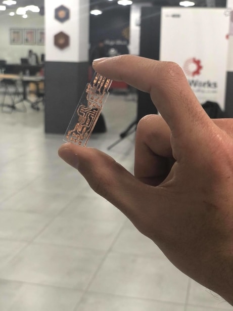
After Finishing the assignment i wanted to try to make another ISP using viynalcutter and acrylic also using mods and here is the process
A beautiful fail
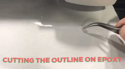
- First i have put epoxy roll in the viynalcutter and followed the process as week 3 Click here to see the documentation then after placing the roll i used mods to control the machine and entered the outline in order to place the acrylic in the right position then :
- And then the viynalcutter started cutting the outline “interior” on the epoxy :
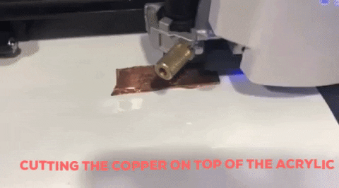
- Then i placed the acrylic and on top i placed copper then i entered the traces file and the viynalcutter started cutting :
here i placed the copper on top :
here the machine started cutting :
- After the viynalcutter finished the job me and my instructor started to pull out the exceeded copper :
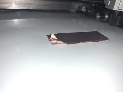
And ended up with this beautiful acrylic ISP :
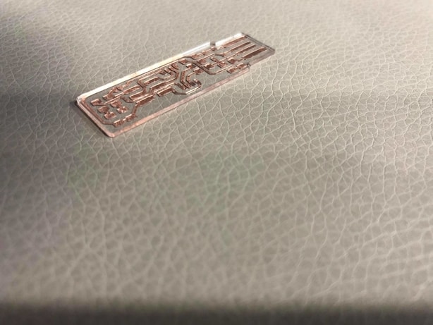
but unfortunately when it came to soldering it did not work so well and i had 2 issues, the first issue that the acrylic started to bend with the heat, the second issue that the copper was not sicky enough so when i was soldering if i dragged or moved my hand just a little bit the traces will come off the acrylic, and here is a look for it :
Here some of the traces went off because its not sticky enough:
Here it bend because of the heat :
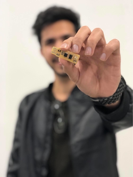
The Hero shot for the individual assignment :