18. Machine design
Arduino CNC Machine Foam Cutting
Assignments for week 17 :
-
This week we have a group assignment only .
-
The group assignment for this week is to design a machine that includes mechanism +actuation +automation
-
build the mechanical parts and operate it manually
-
document the group project and your individual contribution
File Download
The idea behind the machine :
- We have chosen to make this machine because its not available in the lab also because it can make easy and beautiful 3D,2D parts
Arduino CNC Machine Foam Cutting Mechanical part :
In this week we worked on a CNC Foam Cutting Machine, with 3-axis, where the machine moves in two axis forward and backward, and rotate around the Z-axis.

This machine can cut 2D shapes, as well as 2.5D shapes or 3D symmetrical shapes.
Arduino CNC Foam Cutting Machine :
We based our design on Arduino CNC Foam Cutting Machine, because the machine uses aluminum extrusion profiles 2020 easier to assemble, also reduces the time building the machine because of the COVID-19 pandemic and lockdown.
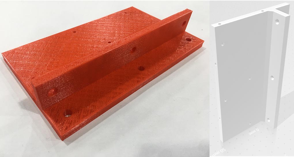
And made some upgrades on the machine rail system to be more rigid, where the new design has one more rail on each side and the 3D files were changed also to be adjusted to the new design.
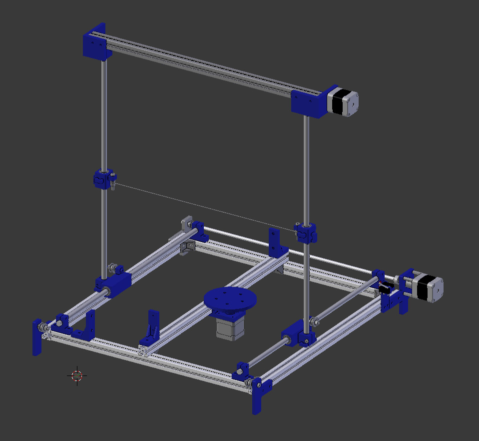
Original design !! :
Overall, in terms of construction and rigidity the design is probably not that good, but In my opinion making a function machine with minimum parts possible and still to be able to get the job done.
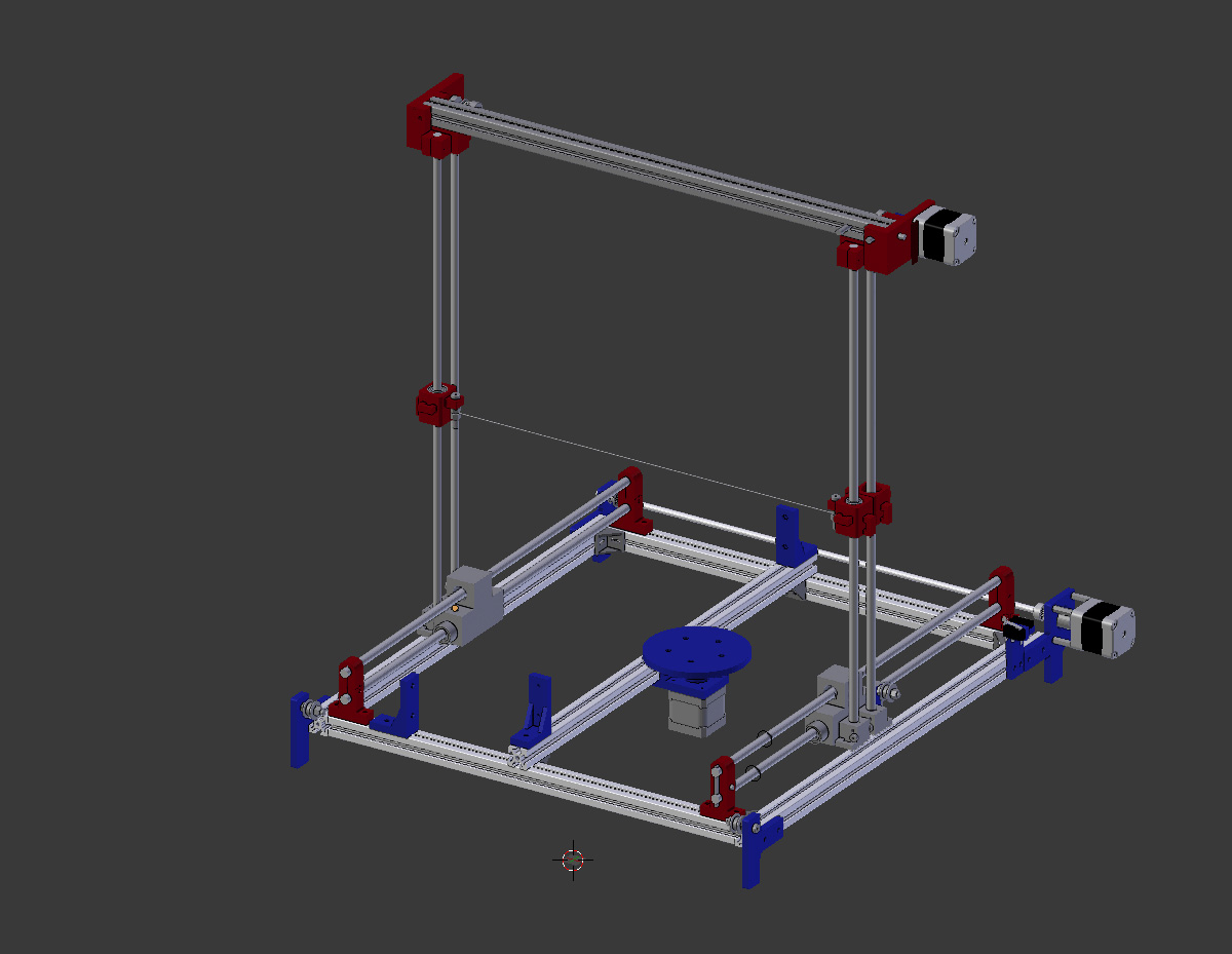
Modified design !!:
In this design we wanted the machine to be more rigid so we have made those changes :
-
First we have added one more linear rail for each moving axis in each side .
-
Second we have edited the 3D models in order to fit the new design .
-
Third we have used a flexible Coupler instead of the shaft Coupler (printed one) .
-
Finally we have replaced the linear rod from 10mm to 8mm and the bearings also .
-
And you can see the changes we have made in the picture below, the red parts !! .
Bill of material for screws :
| Screw type | Qty |
|---|---|
| M3x30 | 14 |
| M4x25 | 10 |
| M4x30 | 10 |
| M5x10/12 | 46 |
| M5x15 | 14 |
| M5x25 | 10 |
| M5x30 | 10 |
Bill of material for 3D printed files :
| Screw type | Qty |
|---|---|
| Foam tightener | 4 |
| Shaft clamp 8mm | 4 |
| X-axis bracket 3 (v2 for 5mm pulleys).STL | 1 |
| X-axis stepper mounting bracket | 1 |
| Z-axis motor mounting bracket | 1 |
| Z-axis platform | 1 |
| Micro switches holder | 1 |
| Sliding Block side 1- X-axis | 1 |
| Sliding Block side 2- X-axis | 1 |
| Y-axis bracket bearing | 1 |
| Y-axis bracket motor | 1 |
| Y-axis sliding block | 2 |
| Arduino case | 1 |
| Extra parts | |
| corner for profile 2020 | 2 |
| spacer | 4 |
Challenges :
We have faced some challenges while making this machine and here is a list of what we have faced :
-
The main problem we have faced is that the store we have ordered the pieces from got delayed to reach us because of the lockdown, also we have received some parts that were not as we ordered which caused a lot of missing time and delayed us even more in remodifying the mechanical pieces .
-
Also there were some pieces that we could not find in stores so we designed those parts and 3D printed them, However we know that 3D printing those partswas not the best solution .
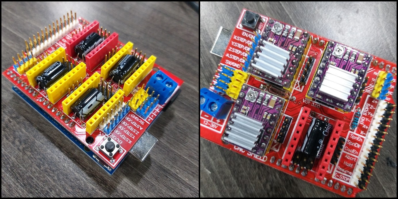
Arduino CNC Machine Electronics part :
In this part we will build Arduino CNC Foam Cutting Machine. The machine is inspired by the work found here.
This is a team working task and different students will be working on different parts. My part and my colleague Aziz is to work on electronics and softwares, including drivers, boards, motors, hot wire and control programs.
Electronics BOM
| Item | Qty. | Source |
|---|---|---|
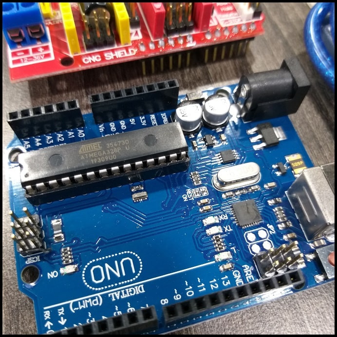
| ARDUINO UNO - R3 | 1 pcs. | Local market |
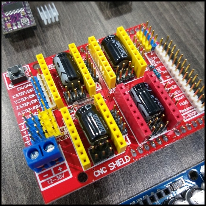
| ARDUINO CNC SHIELD V3 | 1 pcs. | Local market |
| DRV8825 STEPPER MOTOR DRIVER MODULE | 4 pcs. | Local market |
| STEPPER MOTOR 1.8° PER STEP, 1.7 A, 0.36 N.M (NEMA17) | 3 pcs. | Local market |
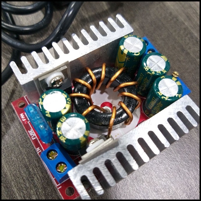
| DC-DC STEP DOWN15A CONVERTER 4-32V 12V TO 1.2-32V BUCK ADJUSTABLE | 1 pcs. | Local market |
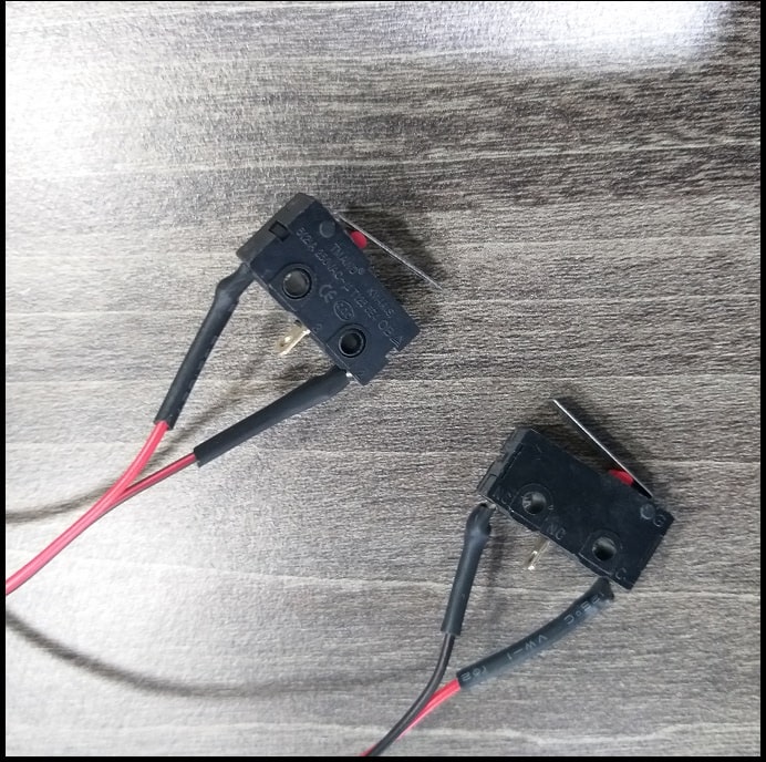
| MICRO NORMALLY OPEN CLOSE LIMIT SWITCH | 2 pcs. | Local market |
| Hot wire | 2 m | Local hardware store |
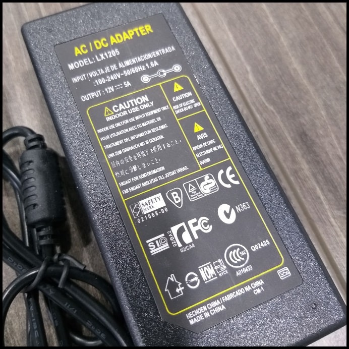
| ADAPTER 12V 5A POWER SUPPLY AC/DC | 1 pcs. | Local market |
- The Arduino Uno is where the GRBL will be installed and will control the machine.
- DRV8825 drivers will control the steppers which provide motion.

- Arduino CNC shield interfaces DRV8825 drivers to Arduino board.
- DC-DC converter will control the temperature of the hot wire
- Limit switches will define the zero or home position of +X and +Y axes.
- Hot wire will heat cut the foam. Hot wire should maintain uniform temperature along its length when it heats up.
- And finally, the adaptor will supply power to the whole system.
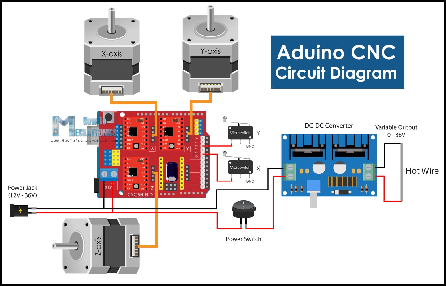
Circuit Diagram :
- The image below shows how different components are connected to each other. Note how all components are interfaced to Arduino board using the CNC shield. This will make connected compact and easier to complete.
Driver Resolution :
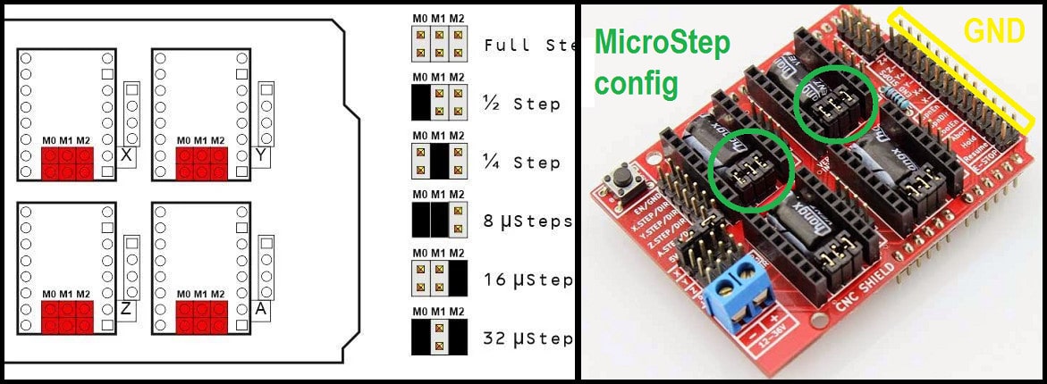
- The DRV8825 driver can be set to drive stepper motors at different resolutions. The driver resolution selectors have 100 kOhm pull-down resistors, which makes them level LOW if there are left unconnected.
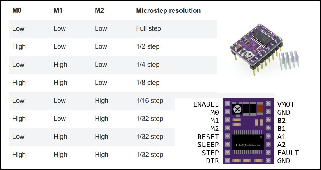
- The CNC shield has connections to resolution selectors and jumpers can be used to set the required resolution. A connected jumper will drive the selector pin (M0, M1, M2) to level high. The image below shows some examples for driver resolution for DRV8825. In our machine will use 1/16 stepper resolution.
Arduino CNC machine Software :
- Two programs will be used to control the machine. The first is GRBL firmware which will installed into Arduino board and enable it to understand g-codes, and the other is g-code sender that will be installed to PC and communicate with Arduino board and send g-codes.
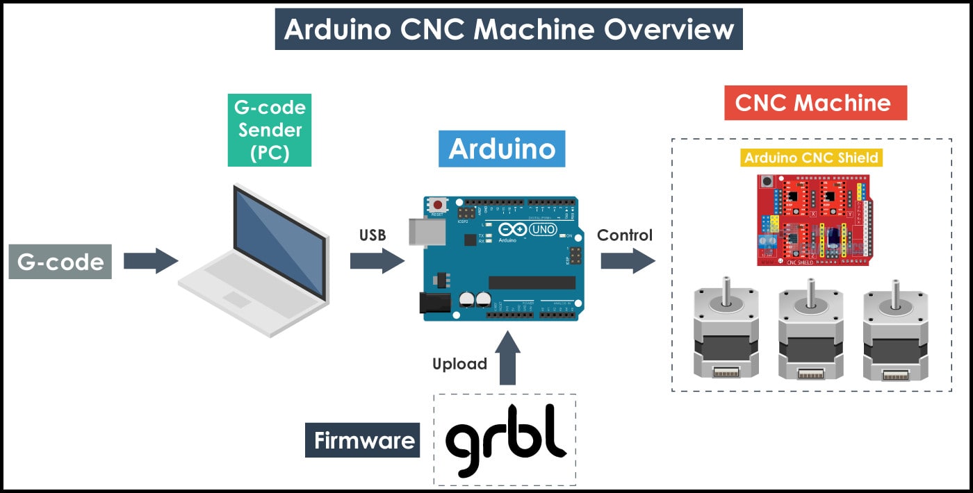
GRBL Firmware :
GRBL is a firmware for Arduino board running on ATmega328P microprocessor. GRBL accepts g-code as inputs and generates outputs at Arduino board pins. Compared to industrial CNC machines, when GRBL is used there is no need for any ports to control the machine, only the USB port connected to Arduino board. In other words, when GRBL firmware is installed to Arduino board, it will read g-codes and control the machine accordingly. To know more about GRBL, check the project page.
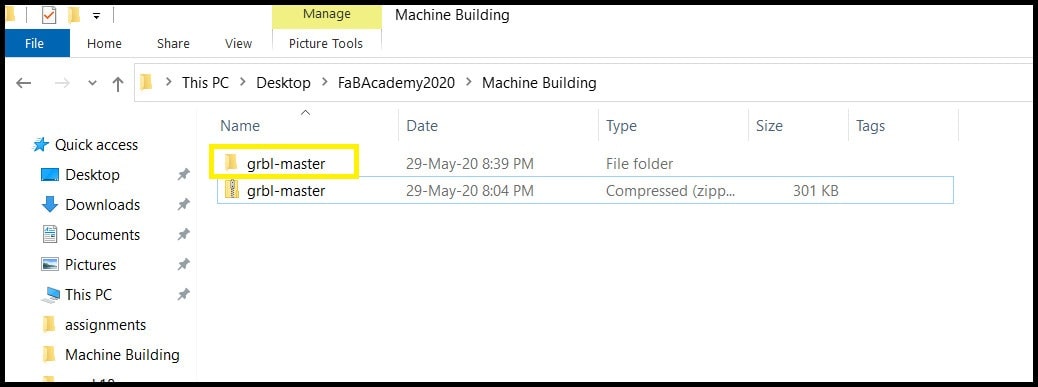
- Step 1: Download GRBL firmware and extract it and copy the folder “grbl-master”. Do not copy this folder to “Arduino library directory!”
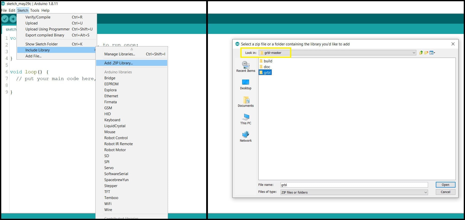
- Step 2: In Arduino IDE go to “Sketch > Include Library > Add .ZIP Library…” and from inside “grbl-master” folder locate “grbl” folder. Click open.
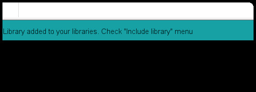
- You should receive the message below.
- Step 3: Go to “File > Examples > grbl > grblUpload”, select the Arduino board (UNO in our case) and the COM port, click upload.
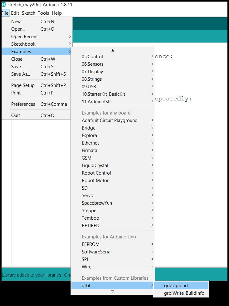
- Note that the firmware used most of the board memory.
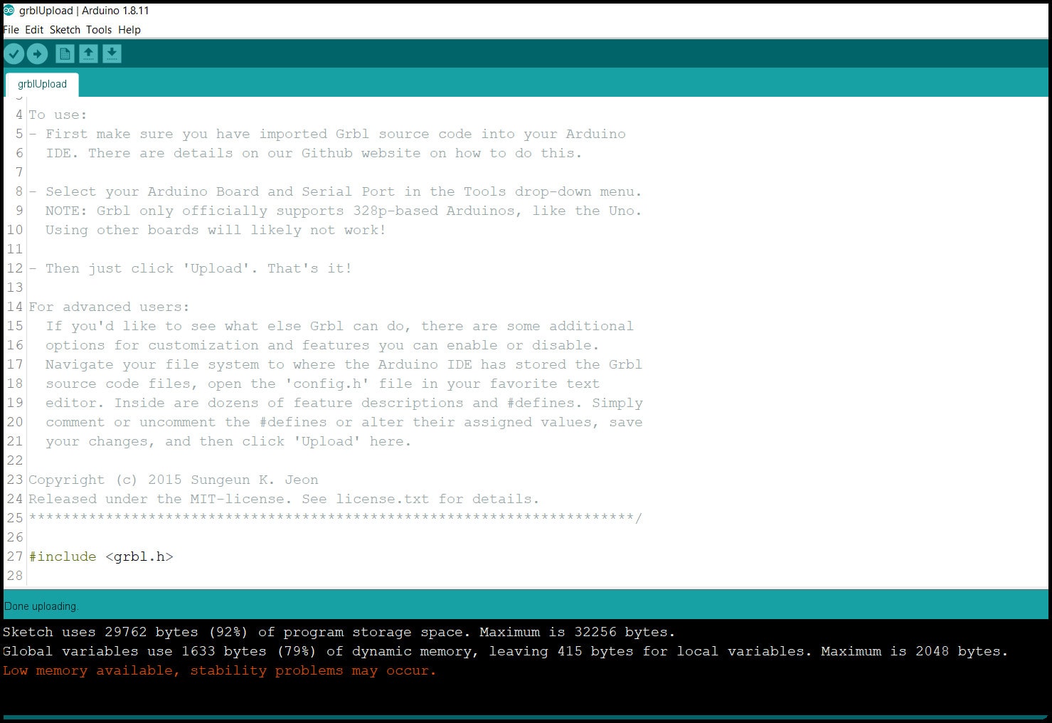
-
Step 4: Open the “Serial Monitor” and set baud rate to 115200. You should see “Grbl 1.1h [‘$’ for help] ” in serial monitor. Type “$$” and send, settings list will appear. We will modify these settings to fit with our machine using the GRBL controller software or g-code sender.
-
Step 5: Since we don’t have a Z-axis switch, we should define that in the config.h file of GRBL. Go to “Arduino library directory > grbl” and open config.h, then find the following parts
// NOTE: Defaults are set for a traditional 3-axis CNC machine. Z-axis first to clear, followed by X & Y.
#define HOMING_CYCLE_0 (1<<Z_AXIS)                // REQUIRED: First move Z to clear workspace.
#define HOMING_CYCLE_1 ((1<<X_AXIS)|(1<<Y_AXIS))  // OPTIONAL: Then move X,Y at the same time.
// #define HOMING_CYCLE_2                         // OPTIONAL: Uncomment and add axes mask to enable

// NOTE: The following are two examples to setup homing for 2-axis machines.
// #define HOMING_CYCLE_0 ((1<<X_AXIS)|(1<<Y_AXIS))  // NOT COMPATIBLE WITH COREXY: Homes both X-Y in one cycle.

// #define HOMING_CYCLE_0 (1<<X_AXIS)  // COREXY COMPATIBLE: First home X
// #define HOMING_CYCLE_1 (1<<Y_AXIS)  // COREXY COMPATIBLE: Then home Y
and change it to
// NOTE: Defaults are set for a traditional 3-axis CNC machine. Z-axis first to clear, followed by X & Y.
//#define HOMING_CYCLE_0 (1<<Z_AXIS)                // REQUIRED: First move Z to clear workspace.
//#define HOMING_CYCLE_1 ((1<<X_AXIS)|(1<<Y_AXIS))  // OPTIONAL: Then move X,Y at the same time.
// #define HOMING_CYCLE_2                         // OPTIONAL: Uncomment and add axes mask to enable

// NOTE: The following are two examples to setup homing for 2-axis machines.
// #define HOMING_CYCLE_0 ((1<<X_AXIS)|(1<<Y_AXIS))  // NOT COMPATIBLE WITH COREXY: Homes both X-Y in one cycle.

#define HOMING_CYCLE_0 (1<<X_AXIS)  // COREXY COMPATIBLE: First home X
#define HOMING_CYCLE_1 (1<<Y_AXIS)  // COREXY COMPATIBLE: Then home Y
- Save the file and reupload the “grblUpload” sketch to our Arduino board.
GRBL Controller Software (g-code Sender) :
This software will generate g-codes according to job and send those codes to Arduino board (which knows how to read g-codes now!). We will use Universal G-code Sender.
-
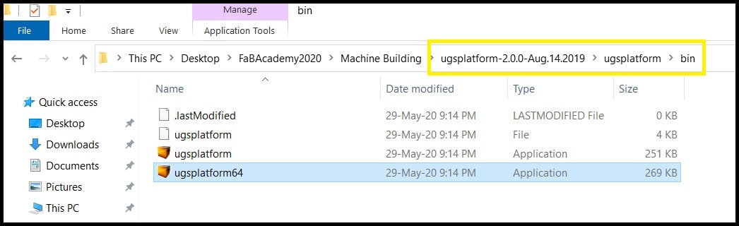
Step 1: Install JAVA Runtime Environment to your PC from here. The GRBL controller is a JAVA program and runtime environment should be installed. You may need to create an account.
-
Step 2: Go to download page and download 2.0 Platform version and extract the zip file. Inside extracted file open “ugsplatfrom > bin” and run one of the executable files (ugsplatform64 in my case).
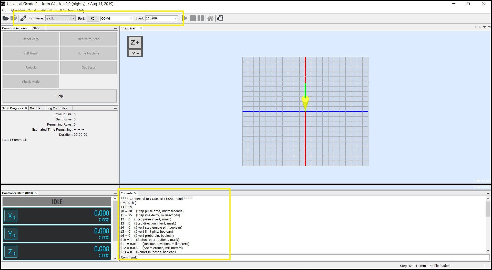
- Step 3: Connect to Arduino board. Set baud rate to 115200 and the right COM port. Click on “Connect/Disconnect” button. In the console window you should see connection confirmation and defined settings.
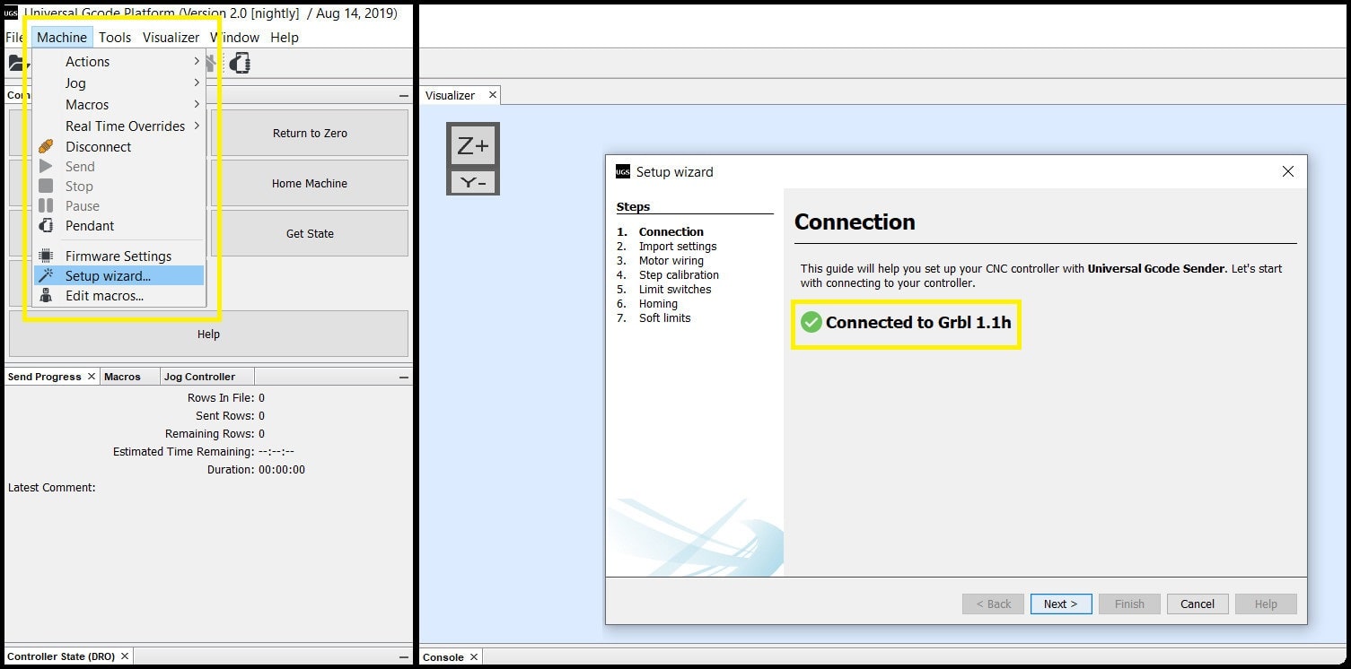
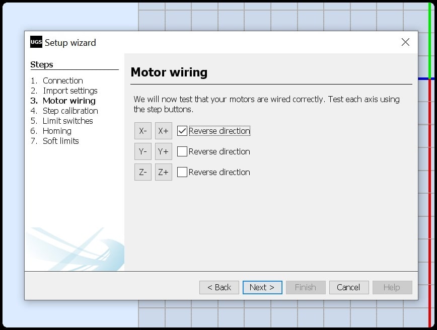
- Step 4: To configure the machine, we will use the built in setup wizard. Go to “Machine > Setup wizard…”. A new window will appear, which will confirm connection to GRBL.
Testing System Component :
Steppers and Limit Switches :
-
We tested system components before assembly to the mechanical part of the machine.
-
First we connected the CNC shield to Arduino board and put a jumper to M2 pins for each axis (1/16 resolution), then connected the DRV8825 stepper driver.
- Then we connected stepper motors, limit switches for +X and +Y axes, powered the shield with +12 VDC and connected Arduino USB cable.
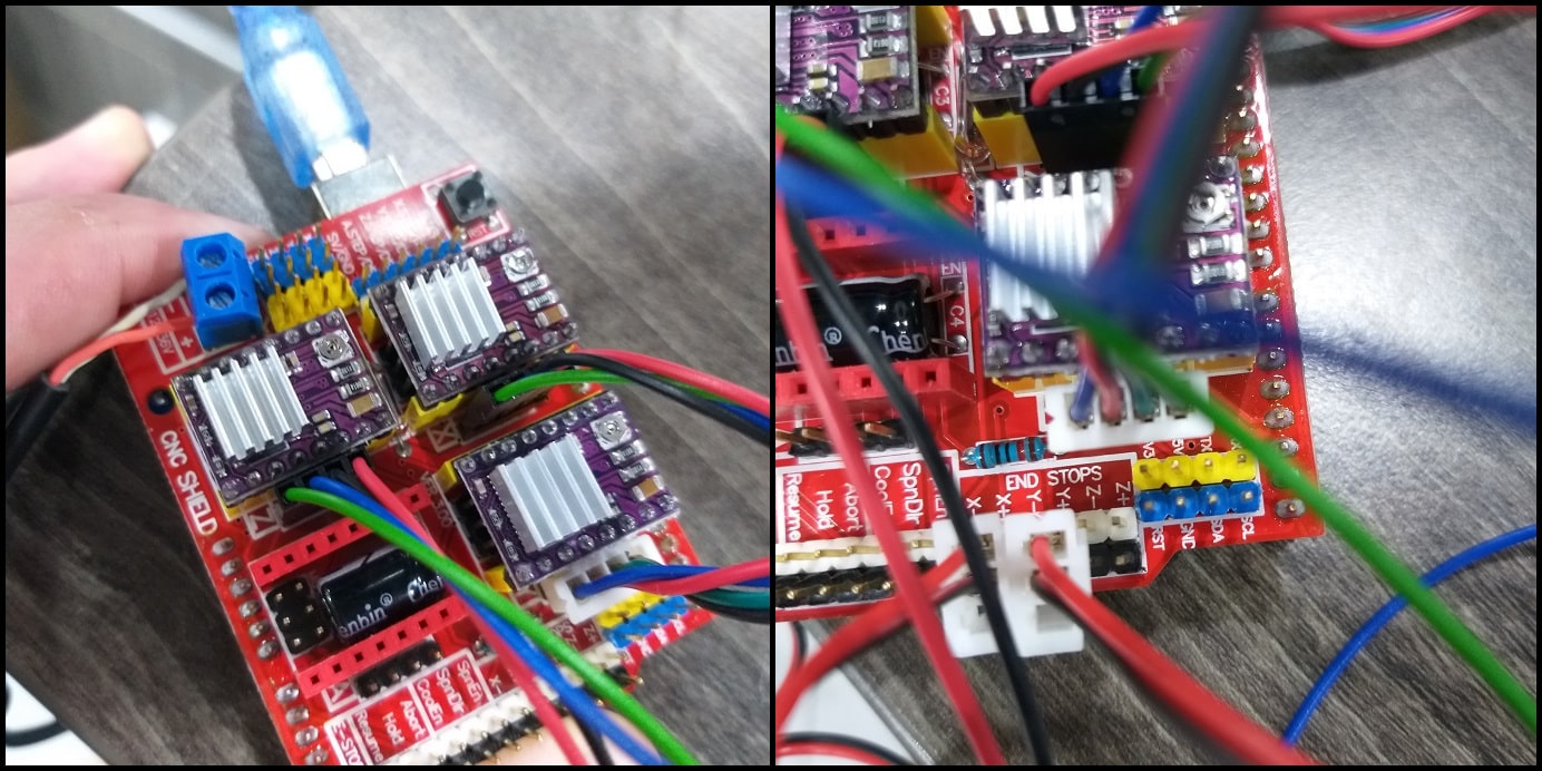
- To test steppers and limit switches, we used the g-code sender. We ran the setup wizard and connected to GRBL in Arduino. In “Motor wiring”, we tested the operation for each stepper and tried to reverse direction.
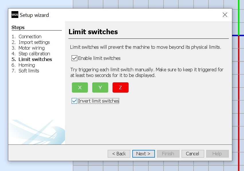
- And we used the “Limit switches” section to test +X and +Y home switches. First limit switches were enabled. Note that the Z axis is rotational and has no home position. In hardware we have normally closed switches. In normal position when the switches are not actuated the switch box will be in green, and should turn into red when the switch is actuated. “Invert limit switches” checkbox is checked to achieve this.
Hot wire :
- First we tested the hot wire using the DC-DC stepdown converter. We tried the hot wire at different voltages. The maximum output we could achieve from the converter was 8.17 VDC, and was not enough to have a good cut.
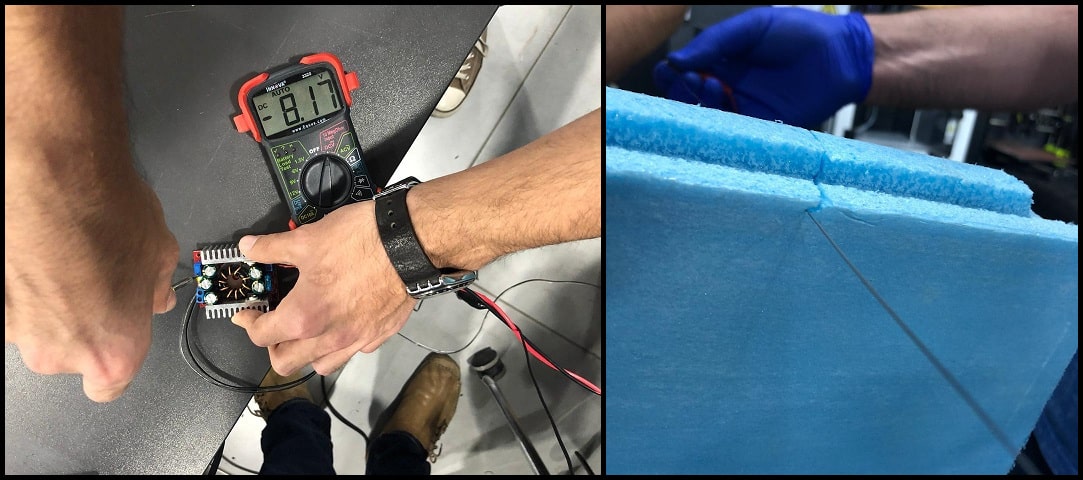
- Then we connected the hot wire to +12 VDC, and removed the converter from the system and directly connected the hot wire to system power adapter. Cutting results were better and acceptable.
Hero Shoot for Machine Electronics part :
- This video shows steppers testing. The X-axis stepper was rotating in reverse direction compared to Y and Z axes steppers. We reversed the rotation of X-axis stepper using the g-code sender.
- This video shows limit switches. When actuated, switches colors turn into red in g-code sender programs. We inverted switches since we are using NC ones.
- This video shows the hot wire cutting test using +12 VDC.
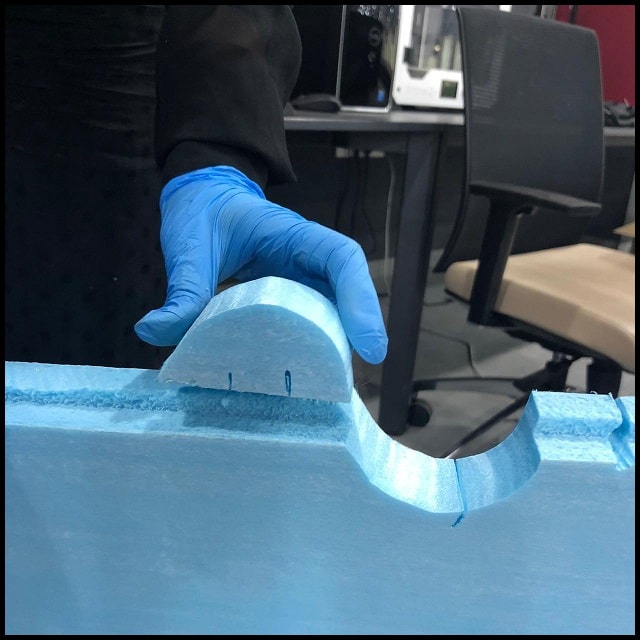
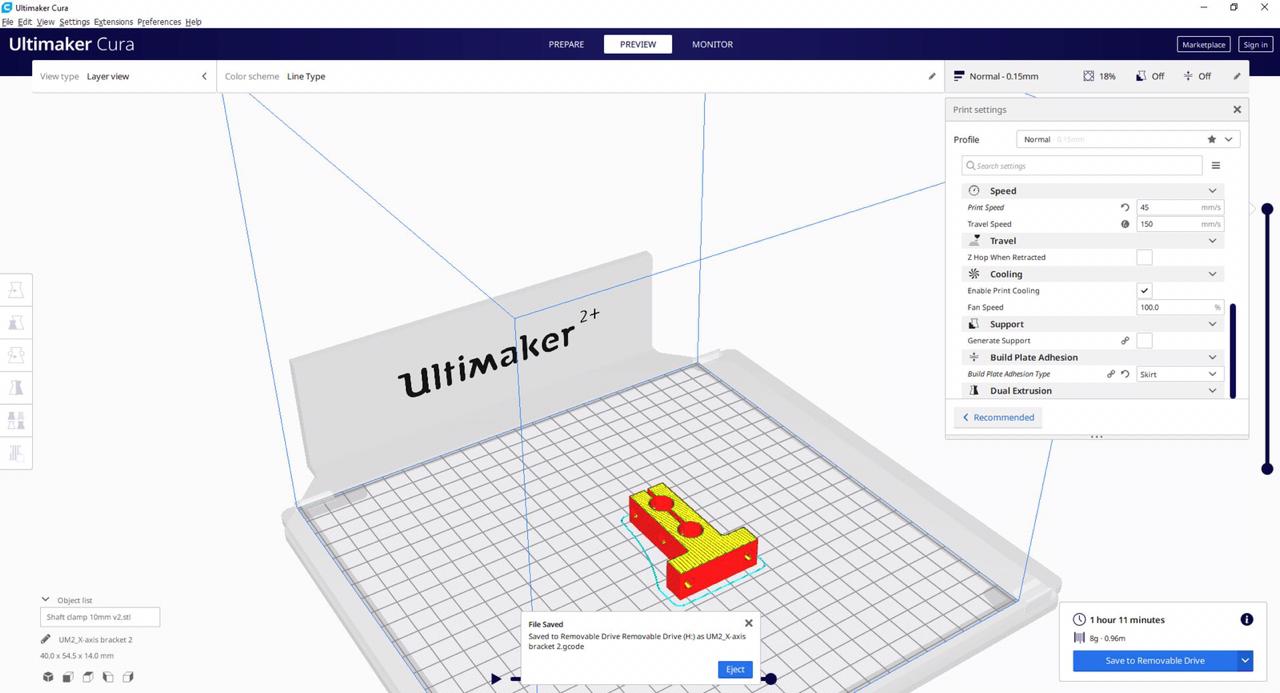
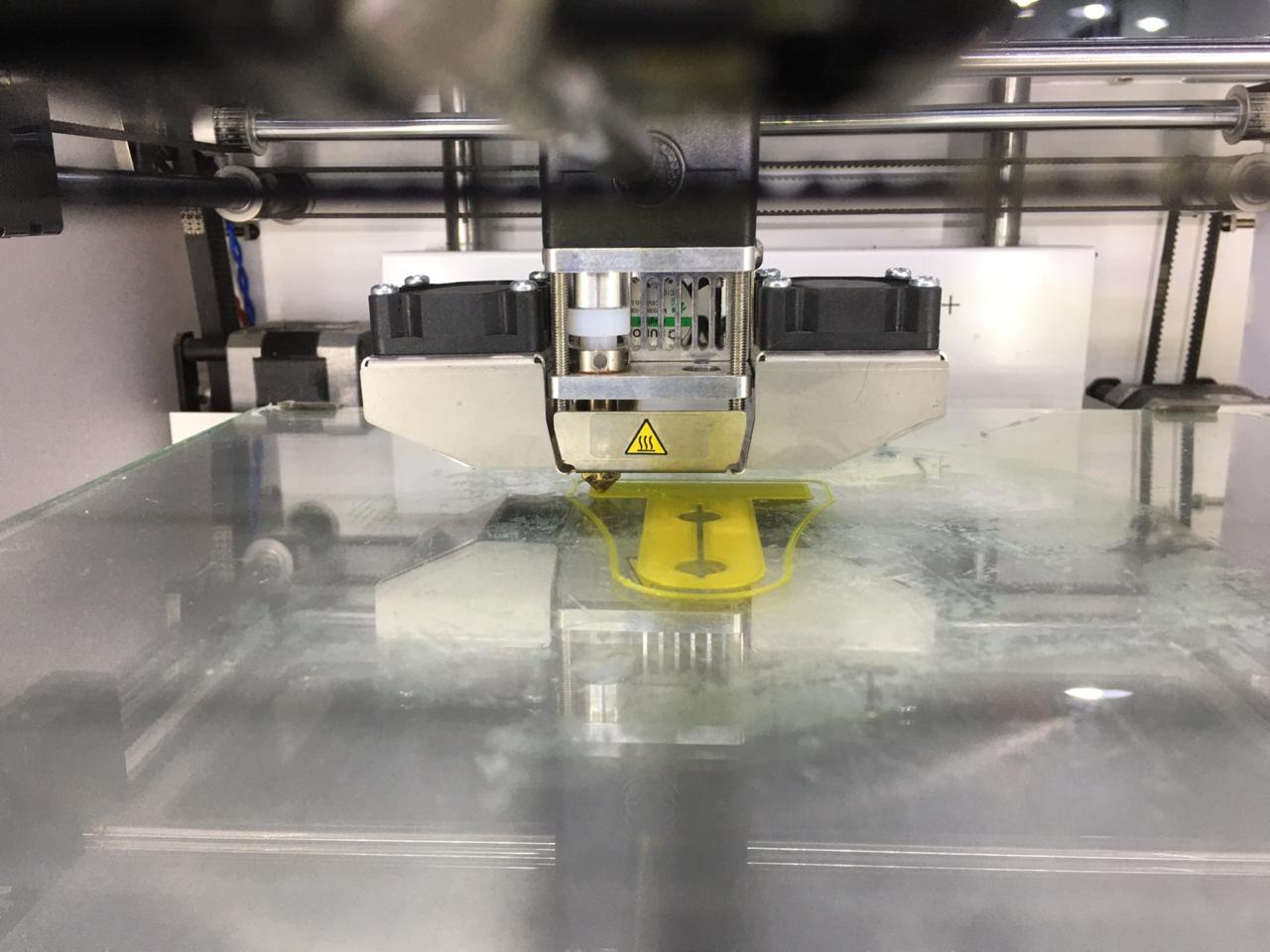
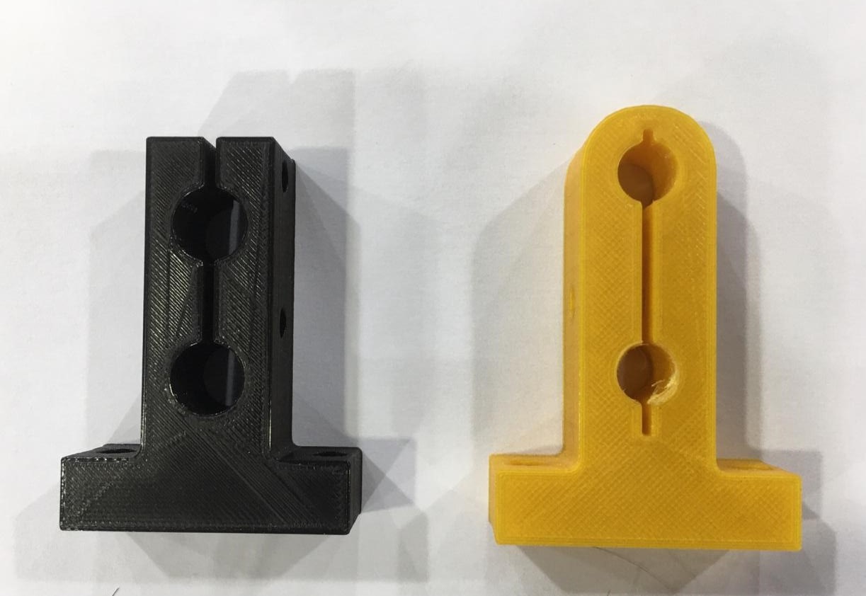
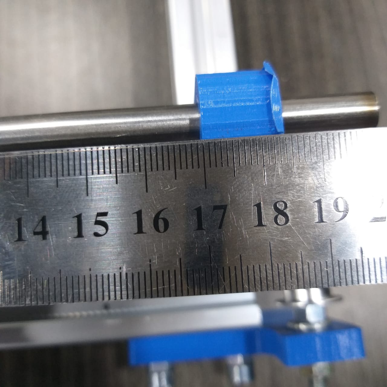
Arduino CNC Machine Foam Cutting Designing part :
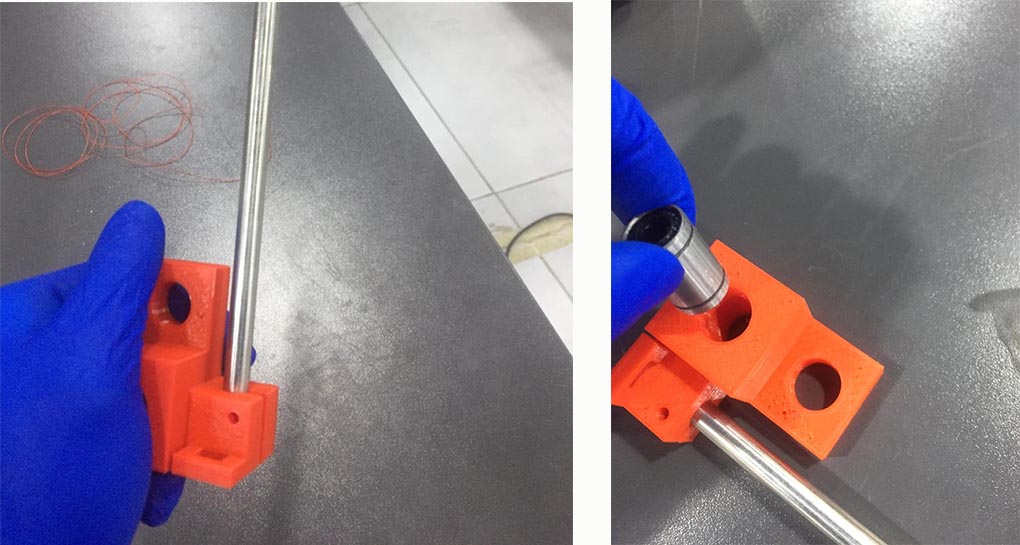
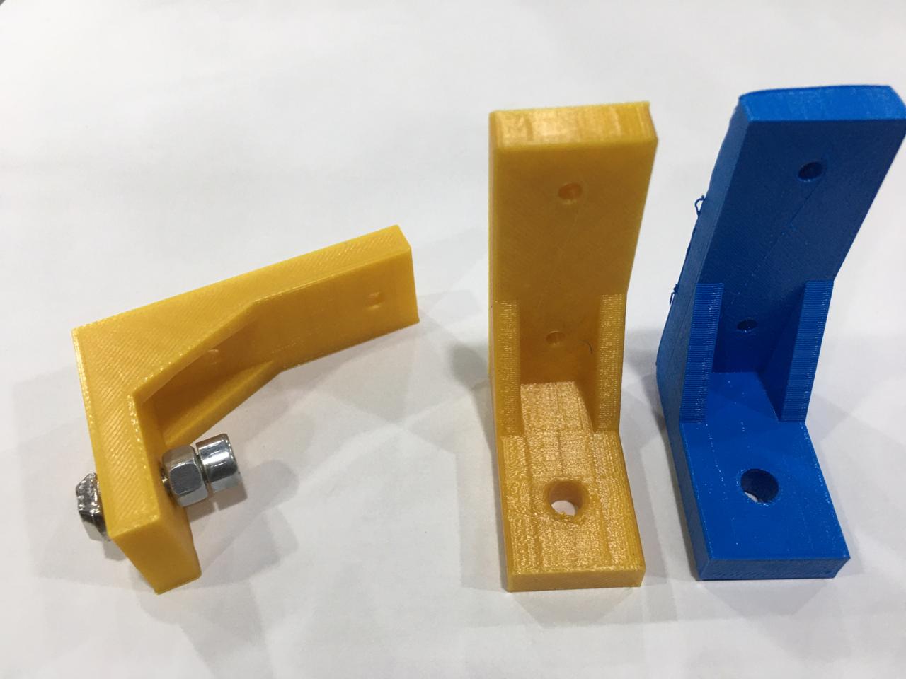
- then tried to modify Shaft clamp 10mm to fit the 2 parallel rods ad first prototype and printing it using same settings :
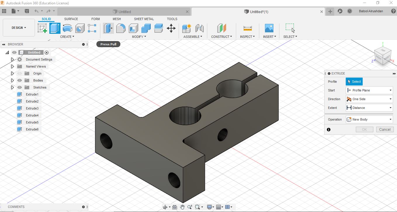
- but sadly it was structurally not the best after trying the physical assembly so the design had been modified :
- Printing the new design :
- comparison between 2 designs :
- Rechecking on the Shaft clamp modified design and it’s measurement :
- Arduino Case design STL and printed perfect fit from first Time :
- checking the fit between 3D printed parts and ordered metallic mechanical parts :
- Here are the foam tightener :
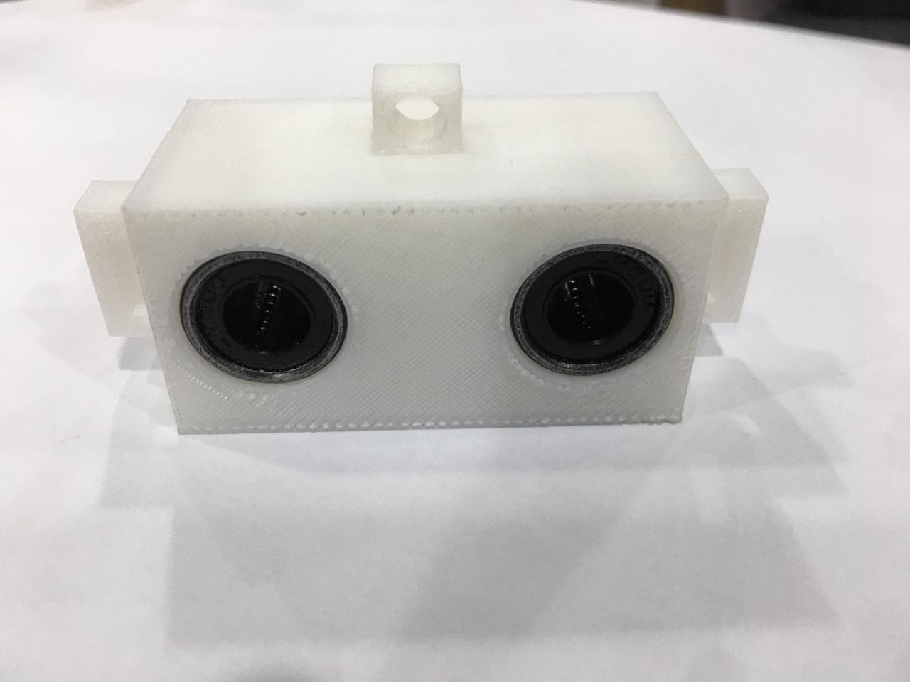
- Y Axis sliding block :
Settings for the 3D printed parts :
Quality
Layer Height: 0.15 mm


Shell
Wall Thickness: 0.7 mm
Top/Bottom Thickness: 0.75 mm

Infill
Infill Density: 18%
Infill Pattern: Grid

Material
Printing Temperature: 200 °C
Build Plate Temperature: 60 °C

Speed
Print Speed: 45 mm/s

Travel
Enable Retraction: Yes
Travel speed : 150


Cooling
Enable Print Cooling: Yes
Fan Speed: 100%


Build Plate Adhesion
Build Plate Adhesion Type: Skirt
Arduino CNC Machine Foam Cutting Assembling :
Here you can see how we assembled the machine :
- First we started with the profile :
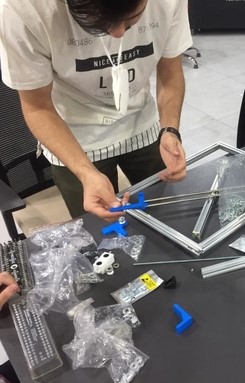
- Next we started to hold the motors :
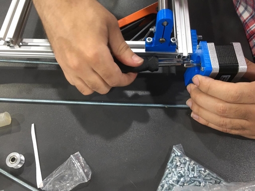
- And here you can see the final Assemble :
Manually moving the machine :
- Here you can see how we started to test manually if the machine is moving properly :
- Here you can see how we put the belt and started to test if its moving properly :
Automatically moving the machine :
- Here you can see how the machine is moving automatically :
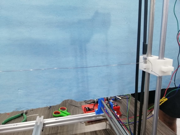
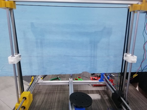
Testing the hot wire :
- Here you can see how we tested and measured the right voltage in order to cut the foam :
Cutting the foam using the hot wire :
Hero shots for this week assignment :
- Here you can see the X axis moving :
- Here you can see the Y axis moving :
- Here you can see the Z Axis moving :
- And here you can see how to connect the Hot wire it must has been connected using springs, however the available strings are not flexible enough therefore we connected them directly to the screws :
-
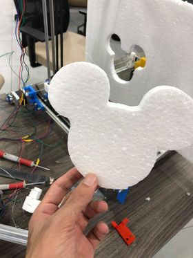
Finally me, Hani, Aziz and Faisal completed the machine and successfully managed to run the machine and cut a mickey mouse shape, Here is a video showing the way the machine cut :
-
And here is a picture showing the final cut :
-
By that we have finished the machine week finally and here is what i have done this week :
-
I have assembled the machine with Faisal and made sure that the structure is fully stable, as for the mechanical part.
- I have programmed and assembled the electronics that we used in the machine with Aziz, as for the electrical part.
- I have written all the documentation needed for this week assignment and finalized it.
The link for the machine week
- please click here